
 My Inquiry
 My Account


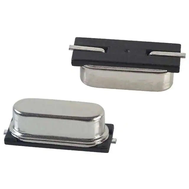
Microchip Technology VXM9-9011-51M8400000
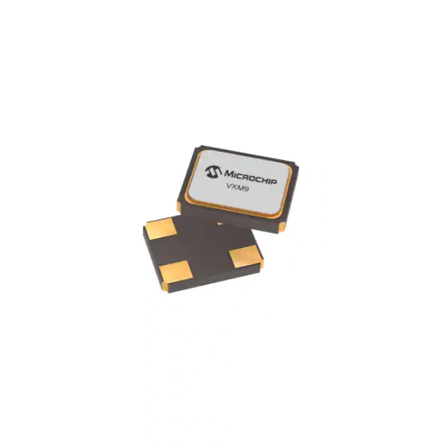
- Part No.:
- VXM9-9011-51M8400000
- Manufacturer:
- Microchip Technology
- Category:
- Crystals
- Package:
- -
- Datasheet:
-
 VXM9-9011-51M8400000.pdf
- Description:
- 2.0X1.65 SMD CRYSTAL
- Quantity:
- Payment:

- Shipping:

Inventory:400
Please send an inquiry. Send us your inquiry, and we will respond immediately.
Product details
Overview
VXM9-9011-51M8400000 from Vectron International is a 51.84 MHz fundamental-mode AT-cut quartz crystal resonator in a 2.0 × 1.6 mm ceramic SMD package, rated for -40 °C to +85 °C operation with ±10 ppm frequency stability and 12 pF load capacitance, used as the primary timing reference in telecom synchronization circuits.
For engineers reviewing the VXM9-9011-51M8400000 datasheet, VXM9-9011-51M8400000 pinout, VXM9-9011-51M8400000 application, or VXM9-9011-51M8400000 equivalent, key selection criteria include its ±10 ppm stability over industrial temperature range, 12 pF load capacitance requirement, low 80 Ω ESR at 51.84 MHz, RoHS-compliant lead-free termination, and MSL 1 reflow compatibility.
Technical Context
This 51.84 MHz crystal operates in fundamental mode using an AT-cut quartz blank, optimized for stable oscillation in Pierce-type oscillator circuits. Its 12 pF load capacitance and ±10 ppm total stability (including tolerance, aging, and temperature drift) meet Stratum 3E and ITU-T G.8262 compliance requirements for telecom infrastructure clocks.
The device features gold-over-nickel contact pads compatible with SnPb and Pb-free soldering, meets MIL-STD-883 mechanical reliability standards, and supports reflow per J-STD-020 profile with peak temperature ≤260 °C and time above 217 °C between 60–150 seconds.
Key Specifications
| Parameter | Value and Actual Design Meaning |
|---|---|
| Nominal Frequency | 51.84 MHz - precise value required for Ethernet PHY clocking and SONET/SDH line timing |
| Frequency Stability | ±10 ppm over -40 °C to +85 °C - ensures timing accuracy across full industrial operating range |
| Load Capacitance | 12 pF - must match external capacitor network in oscillator circuit for accurate frequency pull |
| ESR | 80 Ω - low resistance enables reliable start-up and low phase noise in high-speed clock generators |
| Aging (1st year) | ±5 ppm at 25 °C - contributes to long-term frequency predictability in deployed systems |
| Operating Mode | Fundamental, AT-cut - eliminates spurious modes and simplifies oscillator design vs. overtone crystals |
| Shunt Capacitance (C₀) | 5 pF - impacts negative resistance margin and oscillator loop gain stability |
Pinout & Package
2.0 × 1.6 × 0.55 mm ceramic SMD package with metalized bottom cover and two active crystal terminals; hermetically sealed, MSL 1 rated.
| Pin/Terminal | Circuit Role | Design Meaning |
|---|---|---|
| 1 | Crytal electrode (X1) | Connects to inverter input in Pierce oscillator; requires proper PCB layout to minimize stray capacitance |
| 2 | Case ground | Must be connected to system ground plane to shield crystal from EMI and stabilize resonance |
| 3 | Crytal electrode (X2) | Connects to inverter output and feedback resistor; forms resonant loop with X1 and load capacitors |
| 4 | Case ground | Second ground connection improves mechanical shielding and thermal dissipation uniformity |
Key Features
| Feature | Design Value |
|---|---|
| Fundamental-mode AT-cut quartz | Enables single-stage oscillator design without overtone filters or complex biasing |
| ±10 ppm total stability over -40 °C to +85 °C | Meets Stratum 3E holdover and wander specifications for telecom base stations |
| 12 pF load capacitance | Optimized for use with standard 12 pF external capacitors in microcontroller and FPGA clock circuits |
| 80 Ω ESR at 51.84 MHz | Ensures sufficient negative resistance margin (>5×) for robust start-up under worst-case voltage/temperature |
| Gold-over-nickel terminations | Supports both SnPb and Pb-free reflow without intermetallic degradation or dewetting |
Applications
| 5G Baseband Timing | Ethernet PHY Clocking |
|---|---|
Use Scenario: Precision clock source for 5G NR baseband processors requiring sub-50 ppb frequency accuracy during holdover. IC Role / Device Role / Timing Role: Primary reference oscillator for PLLs generating 100 MHz, 200 MHz, and 500 MHz system clocks. Use Value: ±10 ppm stability and low 80 Ω ESR ensure jitter < 1 ps RMS and reliable lock under thermal cycling. | Use Scenario: Reference clock for 10GBASE-R and 25GBASE-R Ethernet physical layer transceivers. IC Role / Device Role / Timing Role: Fundamental 51.84 MHz timing element feeding clock synthesizers compliant with IEEE 802.3cd. Use Value: 12 pF load capacitance matches standard PHY reference designs; aging ≤ ±5 ppm maintains long-term bit error rate integrity. |
| Synchronization in SDH/SONET | Industrial PLC Real-Time Clock |
Use Scenario: Stratum 3E-compliant timing reference in add-drop multiplexers and digital cross-connect systems. IC Role / Device Role / Timing Role: Input to jitter attenuator ICs (e.g., Si534x) generating synchronous OC-192/STM-64 line clocks. Use Value: ±10 ppm stability over -40 °C to +85 °C satisfies ITU-T G.8262 wander budget for network element holdover. | Use Scenario: High-reliability clock source for programmable logic controllers operating in factory-floor environments. IC Role / Device Role / Timing Role: Direct drive of RTC modules or microcontroller internal oscillators in DIN-rail mounted controllers. Use Value: MSL 1 rating and MIL-STD-883 qualified shock/vibration performance ensure uptime in high-noise industrial settings. |
Equivalent & Alternatives
The following parts are listed as comparable options for similar crystal resonator applications.
| Alternative Part | Technical Difference | Application Difference | Selection Advice |
|---|---|---|---|
| ABM10-51.840MHZ-B2-T | Same 2.0 × 1.6 mm footprint, ±10 ppm stability, but 10 pF load capacitance and 100 Ω ESR | Requires retuning of external capacitors; higher ESR may reduce oscillator margin in low-voltage MCUs | Select only if board layout allows capacitor adjustment and target IC supports 10 pF CL |
| ECX-32L-51.840M | 3.2 × 2.5 mm package, ±10 ppm, 12 pF, but 120 Ω ESR and different pad layout | Not drop-in; requires PCB redesign; better suited for legacy designs with larger footprints | Choose when existing layout uses ECX-32L footprint or higher ESR tolerance is acceptable |
Compared with ABM10-51.840MHZ-B2-T and ECX-32L-51.840M, the VXM9-9011-51M8400000 offers optimal ESR-to-footprint ratio and exact 12 pF matching for modern telecom PHYs, avoiding capacitor recalibration or board spin.
Availability
VXM9-9011-51M8400000 is available at Aetrix Electronics and suitable for 5G infrastructure, high-speed Ethernet equipment, SDH/SONET synchronization systems, and industrial control applications requiring stable component supply with guaranteed long-term availability.
Supply support for VXM9-9011-51M8400000 includes scheduled delivery planning, volume procurement assistance, BOM continuity management, traceable sourcing, and lifecycle availability coordination for OEM customers, industrial embedded developers, connected-device designers, and electronics production programs.
Manufacturer
Vectron International, now part of Microchip Technology, designs and manufactures precision frequency control components including crystals, oscillators, and filters for demanding timing applications.
The VXM9 series targets compact, high-stability crystal resonators for telecom, networking, and industrial systems where miniaturization, thermal robustness, and jitter-critical timing are essential.
FAQ
What is the nominal frequency and operating mode of the VXM9-9011-51M8400000?
The VXM9-9011-51M8400000 is a 51.84 MHz fundamental-mode AT-cut quartz crystal resonator. It operates in fundamental mode-not overtone-and is designed for use in Pierce oscillator configurations with a specified load capacitance of 12 pF. This frequency is commonly used for Ethernet PHY clocking and telecom synchronization applications.
What is the frequency stability specification for the VXM9-9011-51M8400000 over temperature?
The VXM9-9011-51M8400000 has a total frequency stability of ±10 ppm over the operating temperature range of -40 °C to +85 °C. This includes contributions from initial tolerance, temperature variation, aging, and reflow effects, meeting Stratum 3E requirements for telecom infrastructure timing references.
Does the VXM9-9011-51M8400000 require external load capacitors, and what value is needed?
Yes, the VXM9-9011-51M8400000 requires external load capacitors to operate at its nominal frequency. Its specified load capacitance is 12 pF, meaning two identical capacitors (typically ~22–24 pF each, accounting for PCB stray capacitance) must be placed between each crystal terminal and ground in a standard Pierce oscillator configuration.
What is the Equivalent Series Resistance (ESR) of the VXM9-9011-51M8400000, and why does it matter?
The VXM9-9011-51M8400000 has an ESR of 80 Ω at 51.84 MHz. Low ESR ensures sufficient negative resistance margin in oscillator circuits-critical for reliable start-up, low phase noise, and immunity to voltage/temperature variations. Values above 100 Ω may cause marginal or failed oscillation in low-power or high-frequency ICs.
Is the VXM9-9011-51M8400000 compatible with lead-free reflow processes?
Yes, the VXM9-9011-51M8400000 is fully compatible with lead-free reflow. Its gold-over-nickel terminations meet J-STD-020 requirements, supporting peak temperatures up to 260 °C with time above 217 °C between 60–150 seconds. It is rated Moisture Sensitivity Level (MSL) 1, meaning it can be stored indefinitely before assembly without baking.
VXM9-9011-51M8400000 Specifications
- Product attributes
- Attribute value
- Manufacturer:
- Microchip Technology
- Series:
- *
- Package/Case:
- -
- Packaging:
- Strip
- Product Status:
- Active
- Type:
- -
- Frequency:
- -
- Frequency Stability:
- -
- Frequency Tolerance:
- -
- Load Capacitance:
- -
- ESR (Equivalent Series Resistance):
- -
- Operating Mode:
- -
- Operating Temperature:
- -
- Ratings:
- -
- Mounting Type:
- -
- Supplier Device Package:
- -
- Size / Dimension:
- -
- Height - Seated (Max):
- -
VXM9-9011-51M8400000 FAQ
1.How can I place an order for VXM9-9011-51M8400000 through Aetrix?
Please submit a Request for Quotation (RFQ) for VXM9-9011-51M8400000 on Aetrix. Our sales agent will provide a competitive quotation and guide you through the order confirmation once you accept the terms.
2.Are the price and stock information for VXM9-9011-51M8400000 reliable?
The price and inventory of VXM9-9011-51M8400000 are updated periodically and may fluctuate due to market conditions. Stock and pricing data are typically refreshed every 24 hours. Quotation validity for VXM9-9011-51M8400000 is usually 5 days.
3.What payment methods are accepted for VXM9-9011-51M8400000?
We accept Wire Transfer, PayPal, Credit Card, Western Union, MoneyGram, and Escrow for VXM9-9011-51M8400000 transactions.
Note: Certain payment methods may incur a processing fee.
4.How is shipping managed for VXM9-9011-51M8400000?
VXM9-9011-51M8400000 orders can be shipped via leading logistics carriers, including DHL, UPS, FedEx, TNT, or Registered Mail.
Once your VXM9-9011-51M8400000 order is processed, you will receive an email with the shipment details and tracking number.
Note: Tracking information may take up to 24 hours to appear. Express delivery typically takes 3–5 business days.
5.How can I obtain technical support or documentation for VXM9-9011-51M8400000?
For technical support, including VXM9-9011-51M8400000 datasheets, pinout diagrams, or application guidance, please contact our engineering support team. They can provide detailed documentation and assistance for your VXM9-9011-51M8400000 requirements.
6.How does Aetrix verify that VXM9-9011-51M8400000 is sourced from the original manufacturer or authorized distributors?
All VXM9-9011-51M8400000 products on Aetrix are procured from qualified distributors and authorized channels. Our dedicated quality assurance team conducts strict verification, including traceability checks and, if necessary, third-party testing. This ensures that VXM9-9011-51M8400000 meets industry standards.
7.What is the process for return or replacement of VXM9-9011-51M8400000?
All VXM9-9011-51M8400000 units undergo pre-shipment inspection (PSI). If there is an issue with VXM9-9011-51M8400000, returns or replacements are accepted under the following conditions:
1.Quantity discrepancies, incorrect items, or visible external defects (such as breakage or corrosion), acknowledged by Aetrix.
2.The issue is reported within 90 days of delivery.
3.The VXM9-9011-51M8400000 part is unused and in its original packaging.
Return procedure for VXM9-9011-51M8400000:
1.Submit a request within 90 days.
2.Obtain a Return Material Authorization (RMA) from Aetrix.
VXM9-9011-51M8400000 Tags
-
CFS-20632768DZBB
Citizen Finedevice Co Ltd
-
CFS-20632768DZFB
Citizen Finedevice Co Ltd
-
XRCGB32M000F2P01R0
Murata Electronics
-
ECS-250-18-5PX-F-TR
ECS Inc.
-
J49SMH-A-G-G-K-4M0
Jauch Quartz
-
FC4SDCBMF8.0-T1
Fox Electronics
-
ABLS-8.000MHZ-B2-T
Abracon LLC
-
ECS-240-20-5PX-TR
ECS Inc.
-
ABLS-8.000MHZ-B4-T
Abracon LLC
-
ABLS-13.52127MHZ-10-J-4Q-T
Abracon LLC
-
ATS080BSM-1E
CTS-Frequency Controls
-
ECS-184-18-5PX-TR
ECS Inc.
Tech Hub

TTL and CMOS logic families differ in thresholds, loading, output drive, power and timing. This engineering guide compares 74HC and 74HCT, calculates noise margins and checks 3.3 V/5 V compatibility.

A practical engineering guide to 3.3V and 5V logic compatibility, input thresholds, resistor dividers, translator ICs, MOSFET level shifting, I2C pull-ups, timing limits and power-sequencing risks.

The 74HC595 uses push-pull logic outputs, while the TPIC6B595 uses 50 V open-drain DMOS sinks for higher-power loads. This guide compares timing, current limits, 3.3 V interfacing, load wiring, thermal…

The 74HC595 converts serial data into eight stable parallel outputs. This guide covers pin functions, shift and storage timing, OE and MR behavior, drive-current limits, cascading, voltage compatibilit…

A technical comparison of level-sensitive latches and edge-triggered flip-flops, covering timing windows, setup and hold limits, master–slave operation, time borrowing, race-through, HDL inference and…

A D latch stores one bit while Enable controls when data can pass. This reference covers gate-level operation, truth tables, transparency, setup and hold timing, LE versus OE, common ICs and practical …

An SR latch stores one bit through cross-coupled feedback. This engineering reference covers NOR and NAND implementations, truth tables, forbidden-state recovery, gated operation, switch debouncing, fa…

Latch circuits retain one bit through feedback. This technical reference covers SR and D latches, truth tables, transparency, timing limits, latch-versus-flip-flop behavior, applications and common log…

An engineering guide to LED driver operation, constant-current and constant-voltage outputs, linear and switching topologies, dimming, IC selection, calculations, replacement compatibility, and fault c…

Operational amplifier guide covering op amp basics, feedback, ideal vs real op amps, common configurations, buffer circuits, offset, bias current, gain-bandwidth, slew rate, rail-to-rail limits and sel…


