
 My Inquiry
 My Account


Winbond Electronics Corporation W25N01GVZEIR TR
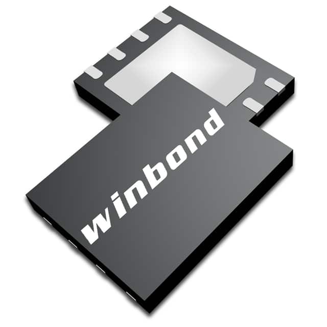
- Part No.:
- W25N01GVZEIR TR
- Manufacturer:
- Winbond Electronics Corporation
- Category:
- Memory
- Package:
- 8-WDFN Exposed Pad
- Datasheet:
-
 W25N01GVZEIR TR.pdf
- Description:
- IC FLASH 1GBIT SPI/QUAD 8WSON
- Quantity:
- Payment:

- Shipping:

Inventory:3,731
Please send an inquiry. Send us your inquiry, and we will respond immediately.
Product details
Overview
W25N01GVZEIR TR from Winbond is a 1G-bit (128MB) Serial SLC NAND Flash memory with Dual/Quad SPI interface, organized into 65,536 pages of 2,048 bytes each and 1,024 uniform 128KB erasable blocks. It supports 104MHz SPI clocking, on-chip 1-bit ECC, hardware/software write protection, and operates from 2.7V to 3.6V for embedded code shadowing and data logging in space-constrained industrial controllers.
For engineers reviewing the W25N01GVZEIR TR datasheet, W25N01GVZEIR TR pinout, W25N01GVZEIR TR application, or W25N01GVZEIR TR equivalent, key selection criteria include buffer vs. continuous read mode behavior (BUF=1 default), WSON-8x6mm package compatibility, Quad I/O timing compliance, and ECC-enabled reliability for long-term firmware storage.
Technical Context
The W25N01GVZEIR TR implements a serial NAND architecture with dedicated internal 2,048-byte page buffer, supporting both Buffer Read (default power-up mode) and Continuous Read modes-enabling single-command sequential access across the full 1G-bit array without intermediate Page Data Read instructions. Its command set includes standard, dual, and quad SPI opcodes with 4-byte addressing support.
It integrates volatile and OTP-configurable registers: Protection Register (SR-1) with BP[3:0], WP-E, and SRP[1:0]; Configuration Register (SR-2) with ECC-E, BUF, and OTP-L bits; and Status Register-3 for real-time ECC-1/ECC-0, P-FAIL/E-FAIL, and BUSY monitoring-enabling robust bad block management via LUT access and programmable ECC enable/disable.
Key Specifications
| Parameter | Value and Actual Design Meaning |
|---|---|
| Memory Density | 1 G-bit (128 M-byte) SLC NAND array, enabling compact firmware/image storage in resource-limited systems |
| Interface Support | Standard/Dual/Quad SPI with up to 104 MHz CLK; enables 50 MB/s continuous transfer using Fast Read Quad I/O |
| Page & Block Structure | 65,536 × 2,048-byte pages; 1,024 × 128 KB blocks-supports deterministic erase granularity and wear leveling |
| ECC Capability | On-chip 1-bit ECC per 528-byte sector; status bits (ECC-1/ECC-0) report correction success/failure per read |
| Power Supply | Single 2.7–3.6 V supply; 25 mA active current and 10 µA standby-suitable for battery-backed or low-power IoT nodes |
| Operating Temperature | –40°C to +85°C industrial grade-validated for use in automotive body control modules and industrial HMIs |
| Endurance & Retention | 100,000 program/erase cycles and 10-year data retention-meets long-life requirements for firmware storage |
Pinout & Package
W25N01GVZEIR TR is housed in an 8-pad WSON 8×6-mm package (JEDEC MO-252, package code ZE), with wettable flank leads for automated optical inspection and high-reliability reflow soldering.
| Pin/Terminal | Circuit Role | Design Meaning |
|---|---|---|
| /CS | Chip Select Input | Active-low enable; must transition high→low after power-up before accepting commands; controls DO high-impedance state |
| DO (IO1) | Data Output / I/O1 | Unidirectional output in Standard SPI; bidirectional I/O in Dual/Quad SPI; used for status/data readback |
| /WP (IO2) | Write Protect Input / I/O2 | Hardware lock for SR-1 when WP-E=1; functions as I/O2 in Quad SPI when WP-E=0 |
| GND | Ground Reference | Primary signal and power return path; requires low-impedance PCB plane connection |
| DI (IO0) | Data Input / I/O0 | Unidirectional input in Standard SPI; bidirectional I/O in Dual/Quad SPI; carries instructions/addresses/data |
| CLK | Serial Clock Input | Master-generated edge-triggered clock; rising edge latches input, falling edge samples output |
| /HOLD (IO3) | Hold Input / I/O3 | Pauses ongoing SPI transaction when low; active-low; functions as I/O3 in Quad SPI when WP-E=0 |
| VCC | Power Supply | 2.7–3.6 V core supply; requires local 1 µF ceramic decoupling adjacent to pin |
Key Features
| Feature | Design Value |
|---|---|
| Continuous Read Mode (BUF=0) | Enables full-array sequential access with one Read command-eliminates repeated Page Data Read overhead in boot code loading |
| Buffer Read Mode (BUF=1) | Default power-up mode; uses internal 2KB buffer for page-aligned reads-optimized for random-access firmware patching |
| Configurable ECC Enable (ECC-E) | Volatile bit in SR-2 allows runtime ECC activation/deactivation-critical for debugging or legacy host controller compatibility |
| Dual/Quad SPI Command Set | Full instruction compatibility with Fast Read Dual/Quad I/O, 4-byte addressing, and Quad Load Program-maximizes throughput in XIP-capable SoCs |
| OTP Protection & Parameter Pages | 10 × 2KB OTP pages + 2KB parameter page allow secure calibration data, device-specific configuration, and immutable firmware signatures |
Applications
| Industrial PLC Firmware Storage | Automotive Infotainment Boot Memory |
|---|---|
Use Scenario: Storing and executing boot firmware and configuration tables in programmable logic controllers with limited PCB area and no parallel bus. IC Role / Device Role / Timing Role: Non-volatile code storage and XIP-capable execution source via Quad SPI interface; replaces parallel NOR in footprint-constrained designs. Use Value: 104 MHz Quad SPI + Continuous Read mode delivers 50 MB/s sustained read throughput-reducing boot time by >35% versus legacy SPI NAND. | Use Scenario: Holding bootloader, OS kernel, and UI assets in head-unit systems requiring AEC-Q100-compliant, long-retention memory. IC Role / Device Role / Timing Role: Primary firmware image repository with on-chip ECC and hardware write protection-ensuring integrity during over-the-air updates. Use Value: 100,000 P/E cycles and 10-year data retention meet automotive lifecycle requirements; -40°C to +85°C rating supports under-dash deployment. |
| Medical Diagnostic Device Log Storage | Smart Energy Meter Firmware Vault |
Use Scenario: Capturing timestamped sensor calibration logs and diagnostic event histories in portable ultrasound and ECG units. IC Role / Device Role / Timing Role: High-reliability data logger with bad block management and LUT-based invalid block tracking-preventing silent corruption in critical health data. Use Value: On-chip 1-bit ECC and real-time ECC status bits (ECC-1/ECC-0) enable immediate error detection and host-level recovery decisions. | Use Scenario: Securing meter firmware, tariff tables, and cryptographic keys against tampering in ANSI C12.22-compliant smart meters. IC Role / Device Role / Timing Role: Tamper-resistant firmware vault using OTP pages for immutable keys and SRP[1:0]/WP-E hardware lock-meeting UL 2900-1 security requirements. Use Value: Hardware write protection (WP-E=1) disables all program/erase operations when /WP grounded-preventing unauthorized firmware modification in field-deployed units. |
Equivalent & Alternatives
The following parts are listed as comparable options for similar Serial NAND Flash applications.
| Alternative Part | Technical Difference | Application Difference | Selection Advice |
|---|---|---|---|
| Macronix MX35LF1GE4AB | Same 1G-bit SLC NAND density, 104 MHz Quad SPI, but uses different OTP page layout and lacks BUF-mode toggle; ECC is fixed-on | Requires modified driver for OTP access and no runtime ECC disable-less flexible for debug or mixed-host environments | Select when OTP structure alignment with existing Macronix-based BOMs is prioritized over configurability |
| Micron MT29F1G01ABAGDWB | 1G-bit SLC NAND with eMMC-like command set; no native SPI interface-requires external SPI-to-NAND bridge IC | Not pin-compatible; adds system complexity and cost; intended for embedded MMC host ecosystems, not direct SPI microcontrollers | Select only if migrating from eMMC platform and SPI-native operation is not required |
Compared with MX35LF1GE4AB and MT29F1G01ABAGDWB, W25N01GVZEIR TR offers unique BUF-mode flexibility, integrated ECC enable/disable control, and true SPI-native operation-making it optimal for new designs requiring firmware agility and minimal external components.
Availability
W25N01GVZEIR TR is available at Aetrix Electronics and suitable for industrial PLC firmware storage, automotive infotainment boot memory, and medical diagnostic log storage requiring stable component supply, long-term lifecycle assurance, and RoHS-compliant packaging.
Supply support for W25N01GVZEIR TR includes scheduled delivery planning, volume procurement assistance, BOM continuity management, traceable sourcing, and lifecycle availability coordination for OEM customers, industrial embedded developers, connected-device designers, and electronics production programs.
Manufacturer
Winbond Electronics is a Taiwan-based global semiconductor manufacturer specializing in specialty memory solutions, including SPI NOR/NAND, PSRAM, and mobile DRAM.
The W25N SpiFlash family was designed specifically to bring NAND density and cost efficiency to SPI-bus constrained systems-enabling code shadowing, XIP execution, and high-volume data logging without parallel bus overhead.
FAQ
What is the default read mode for W25N01GVZEIR TR at power-up?
W25N01GVZEIR TR powers up in Buffer Read mode (BUF=1) as indicated by its "G" suffix in the part numbering scheme. This means the internal 2,048-byte buffer is enabled by default for page-aligned reads. The Continuous Read mode (BUF=0) must be explicitly selected via Write Status Register instruction (1Fh) to SR-2, bit 0. This setting persists until next power cycle or explicit reconfiguration.
Does W25N01GVZEIR TR support Quad SPI commands without external level shifters?
Yes, W25N01GVZEIR TR supports native Quad SPI operation (IO0–IO3) within its 2.7–3.6 V supply range, with all I/O pins tolerant to VCC-referenced signaling. No external level shifters are required when interfacing with 3.3 V microcontrollers. The /WP and /HOLD pins function as IO2 and IO3 respectively in Quad mode when WP-E=0, and timing complies with AC specs up to 104 MHz CLK.
How does the on-chip ECC in W25N01GVZEIR TR operate, and can it be disabled?
W25N01GVZEIR TR implements 1-bit ECC per 528-byte sector using on-die logic. ECC is enabled or disabled via the ECC-E bit (bit 4) in Status Register-2 (SR-2), which is volatile and writable via Write Status Register instruction. When disabled, raw data is returned without correction or status reporting; when enabled, ECC-1/ECC-0 bits in Status Register-3 indicate correction success or uncorrectable error.
What package type does W25N01GVZEIR TR use, and what are its key mechanical features?
W25N01GVZEIR TR uses the 8-pad WSON 8×6-mm package (package code ZE), compliant with JEDEC MO-252. It features wettable flank leads for automated optical inspection, a thermal pad on the bottom for enhanced heat dissipation, and a 0.5 mm lead pitch. This package enables high-density routing and reliable reflow soldering in compact industrial and automotive PCB layouts.
Can W25N01GVZEIR TR be used for secure firmware storage with hardware-based write protection?
Yes, W25N01GVZEIR TR provides hardware write protection via the /WP pin when WP-E=1 in the Protection Register. With /WP tied to GND, all program, erase, and register-write operations-including OTP page programming-are disabled, rendering the entire device read-only. This meets secure boot requirements where firmware immutability must be enforced at the hardware level, independent of software state.
W25N01GVZEIR TR Specifications
- Product attributes
- Attribute value
- Manufacturer:
- Winbond Electronics Corporation
- Series:
- SpiFlash®
- Package/Case:
- 8-WDFN Exposed Pad
- Packaging:
- Tape & Reel (TR)
- Product Status:
- Active
- Programmable:
- Not Verified
- Memory Type:
- Non-Volatile
- Memory Format:
- FLASH
- Technology:
- FLASH - NAND (SLC)
- Memory Size:
- 1Gbit
- Memory Organization:
- 128M x 8
- Memory Interface:
- SPI - Quad I/O
- Clock Frequency:
- 104 MHz
- Write Cycle Time - Word, Page:
- 700µs
- Access Time:
- 7 ns
- Voltage - Supply:
- 2.7V ~ 3.6V
- Operating Temperature:
- -40°C ~ 85°C (TA)
- Grade:
- -
- Qualification:
- -
- Mounting Type:
- Surface Mount
- Supplier Device Package:
- 8-WSON (8x6)
W25N01GVZEIR TR FAQ
1.How can I place an order for W25N01GVZEIR TR through Aetrix?
Please submit a Request for Quotation (RFQ) for W25N01GVZEIR TR on Aetrix. Our sales agent will provide a competitive quotation and guide you through the order confirmation once you accept the terms.
2.Are the price and stock information for W25N01GVZEIR TR reliable?
The price and inventory of W25N01GVZEIR TR are updated periodically and may fluctuate due to market conditions. Stock and pricing data are typically refreshed every 24 hours. Quotation validity for W25N01GVZEIR TR is usually 5 days.
3.What payment methods are accepted for W25N01GVZEIR TR?
We accept Wire Transfer, PayPal, Credit Card, Western Union, MoneyGram, and Escrow for W25N01GVZEIR TR transactions.
Note: Certain payment methods may incur a processing fee.
4.How is shipping managed for W25N01GVZEIR TR?
W25N01GVZEIR TR orders can be shipped via leading logistics carriers, including DHL, UPS, FedEx, TNT, or Registered Mail.
Once your W25N01GVZEIR TR order is processed, you will receive an email with the shipment details and tracking number.
Note: Tracking information may take up to 24 hours to appear. Express delivery typically takes 3–5 business days.
5.How can I obtain technical support or documentation for W25N01GVZEIR TR?
For technical support, including W25N01GVZEIR TR datasheets, pinout diagrams, or application guidance, please contact our engineering support team. They can provide detailed documentation and assistance for your W25N01GVZEIR TR requirements.
6.How does Aetrix verify that W25N01GVZEIR TR is sourced from the original manufacturer or authorized distributors?
All W25N01GVZEIR TR products on Aetrix are procured from qualified distributors and authorized channels. Our dedicated quality assurance team conducts strict verification, including traceability checks and, if necessary, third-party testing. This ensures that W25N01GVZEIR TR meets industry standards.
7.What is the process for return or replacement of W25N01GVZEIR TR?
All W25N01GVZEIR TR units undergo pre-shipment inspection (PSI). If there is an issue with W25N01GVZEIR TR, returns or replacements are accepted under the following conditions:
1.Quantity discrepancies, incorrect items, or visible external defects (such as breakage or corrosion), acknowledged by Aetrix.
2.The issue is reported within 90 days of delivery.
3.The W25N01GVZEIR TR part is unused and in its original packaging.
Return procedure for W25N01GVZEIR TR:
1.Submit a request within 90 days.
2.Obtain a Return Material Authorization (RMA) from Aetrix.
W25N01GVZEIR TR Tags

-
M24C02-WMN6TP
STMicroelectronics

-
AT24C02C-XHM-T
Microchip Technology

-
AT21CS01-STUM10-T
Microchip Technology

-
AT24C02C-SSHM-T
Microchip Technology

-
24LC01BT-I/OT
Microchip Technology

-
M24C02-FMC6TG
STMicroelectronics
-
AT24CS02-SSHM-T
Microchip Technology

-
93LC46BT-I/OT
Microchip Technology
-
AT24C04C-SSHM-T
Microchip Technology

-
24LC01BT-I/SN
Microchip Technology
-
24AA02UIDT-I/OT
Microchip Technology

-
AT24C08C-STUM-T
Microchip Technology
Tech Hub

Counterfeit components can hide behind convincing markings and passing basic function tests. This engineering reference covers source traceability, external inspection, X-ray, XRF, electrical testing, …

A practical engineering and sourcing framework covering lifecycle verification, lifetime-buy calculations, replacement qualification, supplier checks and counterfeit-risk controls.

TTL and CMOS logic families differ in thresholds, loading, output drive, power and timing. This engineering guide compares 74HC and 74HCT, calculates noise margins and checks 3.3 V/5 V compatibility.

A practical engineering guide to 3.3V and 5V logic compatibility, input thresholds, resistor dividers, translator ICs, MOSFET level shifting, I2C pull-ups, timing limits and power-sequencing risks.

The 74HC595 uses push-pull logic outputs, while the TPIC6B595 uses 50 V open-drain DMOS sinks for higher-power loads. This guide compares timing, current limits, 3.3 V interfacing, load wiring, thermal…

The 74HC595 converts serial data into eight stable parallel outputs. This guide covers pin functions, shift and storage timing, OE and MR behavior, drive-current limits, cascading, voltage compatibilit…

A technical comparison of level-sensitive latches and edge-triggered flip-flops, covering timing windows, setup and hold limits, master–slave operation, time borrowing, race-through, HDL inference and…

A D latch stores one bit while Enable controls when data can pass. This reference covers gate-level operation, truth tables, transparency, setup and hold timing, LE versus OE, common ICs and practical …

An SR latch stores one bit through cross-coupled feedback. This engineering reference covers NOR and NAND implementations, truth tables, forbidden-state recovery, gated operation, switch debouncing, fa…

Latch circuits retain one bit through feedback. This technical reference covers SR and D latches, truth tables, transparency, timing limits, latch-versus-flip-flop behavior, applications and common log…


