
 My Inquiry
 My Account


Winbond Electronics Corporation W27C512-45Z
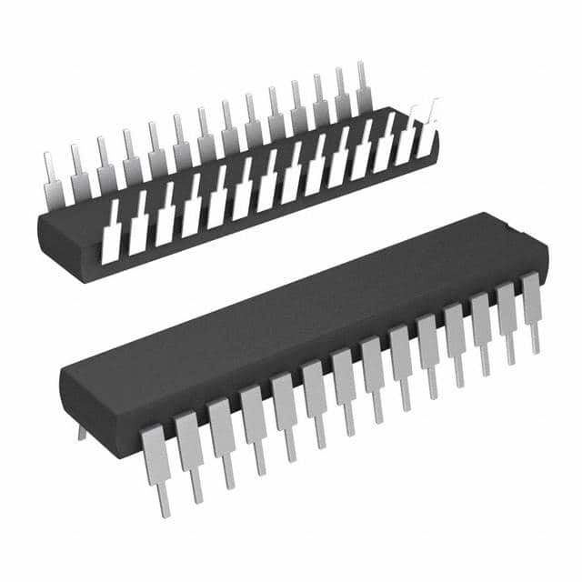
- Part No.:
- W27C512-45Z
- Manufacturer:
- Winbond Electronics Corporation
- Category:
- Memory
- Package:
- 28-DIP (0.600", 15.24mm)
- Datasheet:
-
 W27C512-45Z.pdf
- Description:
- IC EEPROM 512KBIT PARALLEL 28DIP
- Quantity:
- Payment:

- Shipping:

Inventory:2,707
Please send an inquiry. Send us your inquiry, and we will respond immediately.
Product details
Overview
W27C512-45Z from Winbond is a 64K × 8 electrically erasable programmable read-only memory (EEPROM) EPROM, organized as 65,536 × 8 bits, operating on a single 5 V supply with 45 ns maximum access time, +14 V erase voltage, and TTL/CMOS-compatible I/O-used in legacy industrial controller firmware storage and embedded boot code retention.
For engineers reviewing the W27C512-45Z datasheet, W27C512-45Z pinout, W27C512-45Z application, or W27C512-45Z equivalent, key selection criteria include verified 45 ns read timing, lead-free 28-pin DIP packaging, chip-erase capability under electrical control, and compatibility with standard EPROM programmers supporting VPP = 12 V and VPE = 14 V.
Technical Context
The W27C512-45Z implements fully static operation with dual-line output control (CE and OE/VPP), enabling low-power standby mode (≤1 mA) and bus contention avoidance in multi-chip memory arrays. Its erase and program modes require precise voltage sequencing: VPE = 14 V applied to OE/VPP and A9 for chip erase, and VPP = 12 V applied to OE/VPP for byte programming.
Functional modes are determined by voltage levels and timing: erase verify requires VCC = 3.75 V, while read operations use standard 5 V VCC with outputs enabled only when CE = VIL and OE/VPP = VIL. The device supports product identification via A0 and A9 voltage states during special read cycles, returning manufacturer ID "DA" (hex) and device ID "08" (hex).
Key Specifications
| Parameter | Value and Actual Design Meaning |
|---|---|
| Memory Organization | 65,536 × 8 bits - provides 64 KB of nonvolatile storage for firmware or configuration data |
| Access Time (max) | 45 ns - enables direct interface with 22 MHz Z80 or 8086-class microprocessors without wait states |
| Supply Voltage | Single 5.0 V ±5% - eliminates need for auxiliary power rails in legacy 5 V systems |
| Erase Voltage | +14 V on OE/VPP and A9 - enables full-chip electrical erase in ≤100 ms using standard EPROM programmers |
| Programming Voltage | +12 V on OE/VPP - supports byte-level programming compatible with industry-standard UV-EPROM programmers |
| Standby Current | ≤1.0 mA (TTL input) - reduces system power draw during idle periods in battery-backed or energy-sensitive applications |
| I/O Compatibility | TTL/CMOS input thresholds and three-state outputs - ensures interoperability with both logic families and shared data bus architectures |
Pinout & Package
W27C512-45Z is supplied in a lead-free 28-pin plastic dual in-line package (600 mil width), compliant with RoHS Directive 2011/65/EU. Pin 1 is located at the left end of the top row when viewing the marking side with the notch or dot oriented upward.
| Pin/Terminal | Circuit Role | Design Meaning |
|---|---|---|
| A0–A15 | Address Inputs | 16-bit address bus accepting 0x0000–0xFFFF; A9 and A0 have dual roles in erase/ID modes |
| Q0–Q7 | Data Inputs/Outputs | 8-bit bidirectional data bus with three-state outputs controlled by CE and OE/VPP |
| CE | Chip Enable | Active-low chip select; high state forces outputs to high-impedance and enables standby mode |
| OE/VPP | Output Enable / Program-Erase Supply | Low enables output buffer during read; +12 V enables programming, +14 V enables chip erase |
| VCC | Power Supply | +5 V main supply; must be applied before and removed after VPP/VPE to prevent latch-up |
| GND | Ground Reference | Signal and power ground reference for all DC and AC timing parameters |
| NC | No Connection | Pins 16 and 24 in DIP package are unconnected; no internal bonding or function |
Key Features
| Feature | Design Value |
|---|---|
| Electrical Chip Erase | Full 64 KB erase in ≤100 ms using +14 V on OE/VPP and A9-eliminates UV eraser hardware and chamber exposure time |
| Smart Programming Algorithm | Self-terminating pulse-and-verify sequence (up to 25 attempts per byte) ensures reliable programming without over-stress |
| Dual-Voltage Pin (OE/VPP) | Single pin serves as output enable during read and high-voltage supply during program/erase-reduces PCB routing complexity |
| Product Identification Mode | Hardware-readable manufacturer ID (DAh) and device ID (08h) via A0/A9 voltage states-enables automated firmware loader verification |
| Two-Line Output Control | Independent CE and OE/VPP inputs allow hierarchical memory mapping and eliminate bus contention in multi-device systems |
Applications
| Industrial PLC Firmware Storage | Legacy PC BIOS Retention |
|---|---|
Use Scenario: Storing ladder logic firmware in programmable logic controllers where field updates are infrequent but reliability across temperature and vibration is critical. IC Role / Device Role / Timing Role: Nonvolatile boot memory holding executable code executed directly by the CPU upon power-on reset. Use Value: 45 ns access time allows zero-wait-state execution on 80C188-based controllers; electrical erase enables factory reprogramming without UV exposure. |
Use Scenario: Holding BIOS initialization routines in early x86 motherboards requiring field-serviceable firmware replacement. IC Role / Device Role / Timing Role: Primary boot ROM mapped at 0xF0000–0xFFFFF, accessed during POST before DRAM initialization. Use Value: TTL/CMOS compatibility ensures seamless integration with ISA bus logic; +12 V programming supports standard EPROM burners used in service depots. |
| Military Avionics Configuration | Medical Equipment Calibration Data |
Use Scenario: Storing flight control parameter tables in airborne mission computers where radiation tolerance and long-term data retention (>20 years) are mandated. IC Role / Device Role / Timing Role: Static configuration store accessed only during startup or maintenance mode; operates in standby most of the time. Use Value: ≤1 mA standby current minimizes thermal load in sealed avionics enclosures; lead-free DIP packaging meets MIL-STD-1275E EMI and soldering requirements. |
Use Scenario: Retaining sensor calibration coefficients and safety-critical operational limits in diagnostic imaging equipment subject to strict regulatory traceability. IC Role / Device Role / Timing Role: Secure, write-once-after-calibration storage accessed exclusively by embedded microcontroller during self-test sequences. Use Value: Electrical erase capability allows certified recalibration labs to perform full-chip reprogramming under audit-controlled conditions; 3.75 V erase verify ensures margin against data corruption. |
Equivalent & Alternatives
The following parts are listed as comparable options for similar EEPROM/EPROM applications.
| Alternative Part | Technical Difference | Application Difference | Selection Advice |
|---|---|---|---|
| AT27C512R-45PU | 45 ns access, 5 V only, no VPP/VPE dual-function pin; requires external 12 V/14 V switching circuitry | Requires redesign of programmer interface and voltage control logic; lacks built-in product ID mode | Select if existing design uses Atmel-compatible timing and external high-voltage generation is already present |
| MX27C512-45PC | 45 ns access, same 28-pin DIP, but specifies 100 μA max standby current (vs. 1 mA for W27C512-45Z) and no lead-free option in this speed grade | Lower standby draw suits battery-backed systems; RoHS compliance requires alternate part number or waiver | Select for ultra-low-power legacy systems where lead-free is not mandated and 100 μA standby is critical |
Compared with AT27C512R-45PU and MX27C512-45PC, the W27C512-45Z integrates erase/program voltage switching into OE/VPP-reducing external component count-and provides hardware-readable ID codes essential for automated firmware validation in production test environments.
Availability
W27C512-45Z is available at Aetrix Electronics and suitable for industrial PLC firmware storage, legacy PC BIOS retention, and medical equipment calibration data applications requiring stable component supply across extended product lifecycles.
Supply support for W27C512-45Z includes scheduled delivery planning, volume procurement assistance, BOM continuity management, traceable sourcing, and lifecycle availability coordination for OEM customers, industrial embedded developers, connected-device designers, and electronics production programs.
Manufacturer
Winbond Electronics Corporation is a Taiwan-based semiconductor company founded in 1987, specializing in memory ICs, flash memory, and logic devices for industrial and embedded markets.
The W27C512 product line was designed for drop-in replacement of UV-erasable EPROMs in legacy 5 V systems, emphasizing electrical erasability, pin compatibility, and robustness in harsh environmental conditions.
FAQ
What is the maximum allowed VPP voltage for programming the W27C512-45Z?
The W27C512-45Z specifies a VPP programming voltage range of 11.75 V to 12.25 V, with 12.0 V nominal. Exceeding 12.25 V risks oxide breakdown in the floating-gate cells, potentially causing permanent bit failure. The W27C512-45Z datasheet explicitly warns that VCC must be applied before VPP and removed after VPP to prevent latch-up; therefore, any W27C512-45Z programming setup must enforce strict voltage sequencing.
Does the W27C512-45Z support byte-level programming or only full-chip erase?
The W27C512-45Z supports both full-chip electrical erase and byte-level programming. Programming is performed by applying +12 V to OE/VPP while asserting the target address and data, then pulsing CE low for 100 μs. Each byte is verified immediately after programming, and the smart algorithm repeats up to 25 times if verification fails. The W27C512-45Z does not support page or sector erase-only chip-erase is available.
Can the W27C512-45Z be used in a 3.3 V system?
No, the W27C512-45Z is strictly a 5 V device: its DC and AC characteristics-including VIH (2.2 V min), VOL (0.45 V max), and VCC operating range (4.75–5.25 V)-are specified only for 5 V operation. Applying 3.3 V to VCC will result in undefined behavior, failed reads, and inability to enter erase or program modes. The W27C512-45Z has no 3.3 V variant; use of level shifters is not recommended due to timing and voltage margin constraints.
What is the purpose of the A9 pin during erase mode on the W27C512-45Z?
During chip erase, A9 on the W27C512-45Z must be driven to +14 V (VPE) along with OE/VPP to activate the internal erase control circuitry. This dual-voltage requirement prevents accidental erasure from noise or logic-level signals. The W27C512-45Z datasheet confirms A9 = VPE is mandatory for erase entry; omitting it results in no erase action regardless of CE pulsing or other conditions.
Is the W27C512-45Z RoHS-compliant and lead-free?
Yes, the W27C512-45Z is explicitly designated as a lead-free part in Winbond's Ordering Information table (Revision A6, January 2006), confirming compliance with EU RoHS Directive 2011/65/EU. The "Z" suffix denotes lead-free finish on the 28-pin DIP package; this includes matte tin plating over copper leads and halogen-free molding compound. The W27C512-45Z meets JEDEC J-STD-020 moisture sensitivity level MSL-3.
W27C512-45Z Specifications
- Product attributes
- Attribute value
- Manufacturer:
- Winbond Electronics Corporation
- Series:
- -
- Package/Case:
- 28-DIP (0.600", 15.24mm)
- Packaging:
- Tube
- Product Status:
- Obsolete
- Programmable:
- Not Verified
- Memory Type:
- Non-Volatile
- Memory Format:
- EEPROM
- Technology:
- EEPROM
- Memory Size:
- 512Kbit
- Memory Organization:
- 64K x 8
- Memory Interface:
- Parallel
- Clock Frequency:
- -
- Write Cycle Time - Word, Page:
- -
- Access Time:
- 45 ns
- Voltage - Supply:
- 4.75V ~ 5.25V
- Operating Temperature:
- 0°C ~ 70°C (TA)
- Grade:
- -
- Qualification:
- -
- Mounting Type:
- Through Hole
- Supplier Device Package:
- 28-PDIP
W27C512-45Z FAQ
1.How can I place an order for W27C512-45Z through Aetrix?
Please submit a Request for Quotation (RFQ) for W27C512-45Z on Aetrix. Our sales agent will provide a competitive quotation and guide you through the order confirmation once you accept the terms.
2.Are the price and stock information for W27C512-45Z reliable?
The price and inventory of W27C512-45Z are updated periodically and may fluctuate due to market conditions. Stock and pricing data are typically refreshed every 24 hours. Quotation validity for W27C512-45Z is usually 5 days.
3.What payment methods are accepted for W27C512-45Z?
We accept Wire Transfer, PayPal, Credit Card, Western Union, MoneyGram, and Escrow for W27C512-45Z transactions.
Note: Certain payment methods may incur a processing fee.
4.How is shipping managed for W27C512-45Z?
W27C512-45Z orders can be shipped via leading logistics carriers, including DHL, UPS, FedEx, TNT, or Registered Mail.
Once your W27C512-45Z order is processed, you will receive an email with the shipment details and tracking number.
Note: Tracking information may take up to 24 hours to appear. Express delivery typically takes 3–5 business days.
5.How can I obtain technical support or documentation for W27C512-45Z?
For technical support, including W27C512-45Z datasheets, pinout diagrams, or application guidance, please contact our engineering support team. They can provide detailed documentation and assistance for your W27C512-45Z requirements.
6.How does Aetrix verify that W27C512-45Z is sourced from the original manufacturer or authorized distributors?
All W27C512-45Z products on Aetrix are procured from qualified distributors and authorized channels. Our dedicated quality assurance team conducts strict verification, including traceability checks and, if necessary, third-party testing. This ensures that W27C512-45Z meets industry standards.
7.What is the process for return or replacement of W27C512-45Z?
All W27C512-45Z units undergo pre-shipment inspection (PSI). If there is an issue with W27C512-45Z, returns or replacements are accepted under the following conditions:
1.Quantity discrepancies, incorrect items, or visible external defects (such as breakage or corrosion), acknowledged by Aetrix.
2.The issue is reported within 90 days of delivery.
3.The W27C512-45Z part is unused and in its original packaging.
Return procedure for W27C512-45Z:
1.Submit a request within 90 days.
2.Obtain a Return Material Authorization (RMA) from Aetrix.
W27C512-45Z Tags

-
M24C02-WMN6TP
STMicroelectronics

-
AT24C02C-XHM-T
Microchip Technology

-
AT21CS01-STUM10-T
Microchip Technology

-
AT24C02C-SSHM-T
Microchip Technology

-
24LC01BT-I/OT
Microchip Technology

-
M24C02-FMC6TG
STMicroelectronics
-
AT24CS02-SSHM-T
Microchip Technology

-
93LC46BT-I/OT
Microchip Technology
-
AT24C04C-SSHM-T
Microchip Technology

-
24LC01BT-I/SN
Microchip Technology
-
24AA02UIDT-I/OT
Microchip Technology

-
AT24C08C-STUM-T
Microchip Technology
Tech Hub

Counterfeit components can hide behind convincing markings and passing basic function tests. This engineering reference covers source traceability, external inspection, X-ray, XRF, electrical testing, …

A practical engineering and sourcing framework covering lifecycle verification, lifetime-buy calculations, replacement qualification, supplier checks and counterfeit-risk controls.

TTL and CMOS logic families differ in thresholds, loading, output drive, power and timing. This engineering guide compares 74HC and 74HCT, calculates noise margins and checks 3.3 V/5 V compatibility.

A practical engineering guide to 3.3V and 5V logic compatibility, input thresholds, resistor dividers, translator ICs, MOSFET level shifting, I2C pull-ups, timing limits and power-sequencing risks.

The 74HC595 uses push-pull logic outputs, while the TPIC6B595 uses 50 V open-drain DMOS sinks for higher-power loads. This guide compares timing, current limits, 3.3 V interfacing, load wiring, thermal…

The 74HC595 converts serial data into eight stable parallel outputs. This guide covers pin functions, shift and storage timing, OE and MR behavior, drive-current limits, cascading, voltage compatibilit…

A technical comparison of level-sensitive latches and edge-triggered flip-flops, covering timing windows, setup and hold limits, master–slave operation, time borrowing, race-through, HDL inference and…

A D latch stores one bit while Enable controls when data can pass. This reference covers gate-level operation, truth tables, transparency, setup and hold timing, LE versus OE, common ICs and practical …

An SR latch stores one bit through cross-coupled feedback. This engineering reference covers NOR and NAND implementations, truth tables, forbidden-state recovery, gated operation, switch debouncing, fa…

Latch circuits retain one bit through feedback. This technical reference covers SR and D latches, truth tables, transparency, timing limits, latch-versus-flip-flop behavior, applications and common log…


