
 My Inquiry
 My Account


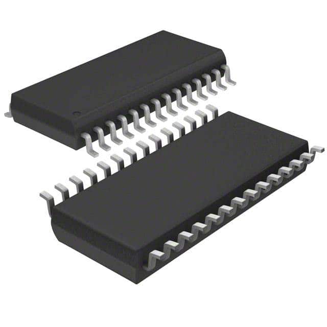
Infineon Technologies W40S11-02H
- Part No.:
- W40S11-02H
- Manufacturer:
- Infineon Technologies
- Category:
- Application Specific Clock/Timing
- Package:
- 28-SSOP (0.209", 5.30mm Width)
- Datasheet:
-
 W40S11-02H.pdf
- Description:
- IC CLK BUFF 10OUT SDRAM 28SSOP
- Quantity:
- Payment:

- Shipping:

Inventory:3,218
Please send an inquiry. Send us your inquiry, and we will respond immediately.
Product details
Overview
W40S11-02 from Cypress Semiconductor Corporation is a 10-output, skew-controlled CMOS clock buffer designed for SDRAM DIMM clock distribution in mobile systems using Intel's Mobile chipsets. It operates from a single 3.3V supply, delivers rail-to-rail CMOS outputs with 15Ω typical impedance, supports DC–133 MHz input frequencies, and features I²C-based serial configuration. It drives two SDRAM DIMMs with <250 ps output skew and 1–5 ns propagation delay.
For engineers reviewing the W40S11-02 datasheet, W40S11-02 pinout, W40S11-02 application, or W40S11-02 equivalent, key selection criteria include skew tolerance, I²C configurability, output enable control, 3.3V rail-to-rail drive capability, and compatibility with mobile SDRAM timing requirements.
Technical Context
The W40S11-02 implements a low-jitter, ten-channel fanout buffer with per-output enable via I²C register mapping (Data Bytes 0–2) or hardware OE pin. All outputs are phase-aligned to BUF_IN with controlled skew (<±250 ps) and propagation delay (1–5 ns).
It uses internal 250 kΩ pull-up resistors on SDATA, SCLOCK, and OE; supports open-drain I²C bus operation with acknowledge pulses; and provides three-state outputs when OE is low or individual SDRAM outputs are disabled via serial configuration.
Key Specifications
| Parameter | Value and Actual Design Meaning |
|---|---|
| Supply Voltage | 3.3 V ±5% - powers core logic and 15Ω CMOS output drivers |
| Input Frequency Range | DC to 133 MHz - supports PC100/PC133 SDRAM clocking |
| Propagation Delay | 1.0–5.0 ns - defines timing margin between BUF_IN and SDRAMx edges |
| Output Skew | ±250 ps - ensures simultaneous clock arrival across two DIMMs |
| Output Impedance | 15 Ω typical - matches transmission lines driving 6" traces with 22 pF loads |
| I²C Interface | Standard 2-wire serial bus - enables dynamic output enable/disable without hardware changes |
| Operating Temperature | 0°C to +70°C - qualified for commercial mobile platform environments |
Pinout & Package
Package: 28-pin, 209-mil Shrink Small Outline Package (SSOP), surface-mount, lead-free compatible.
| Pin/Terminal | Circuit Role | Design Meaning |
|---|---|---|
| BUF_IN (Pin 9) | Clock Input | Primary reference clock input with 1.5 V typical threshold; drives all ten outputs |
| SDRAM0–SDRAM9 (Pins 2,3,6,7,11,18,22,23,26,27) | CMOS Clock Outputs | Skew-controlled buffered copies of BUF_IN; each individually disableable via I²C or OE |
| OE (Pin 20) | Hardware Output Enable | Active-high enable; pulls all outputs to high-impedance when low (internal 250 kΩ pull-up) |
| SDATA (Pin 14) | I²C Data I/O | Open-drain bidirectional line; receives config data and transmits ACK pulses |
| SCLOCK (Pin 15) | I²C Clock Input | Master-generated clock for serial configuration; internal 250 kΩ pull-up |
| VDD (Pins 1,5,10,13,19,24,28) | Power Supply | Seven dedicated 3.3 V connections reduce IR drop and improve noise immunity |
| GND (Pins 4,8,12,16,17,21,25) | Ground Reference | Seven ground pins provide low-inductance return paths for all outputs and logic |
Key Features
| Feature | Design Value |
|---|---|
| 10 skew-controlled outputs | ±250 ps max skew ensures synchronous clock delivery to dual DIMMs |
| I²C serial configuration | Enables per-output enable/disable without redesigning PCB or changing OE logic |
| Rail-to-rail CMOS outputs | Full 0–3.3 V swing compatible with TTL and CMOS SDRAM clock inputs |
| 15 Ω output impedance | Optimized for driving 6" PCB traces terminated with 22 pF loads per DIMM |
| Low-power 3.3 V operation | 160 mA typical supply current at 66 MHz reduces thermal load in space-constrained mobile designs |
Applications
| Mobile Notebook Memory Subsystem | Intel Mobile Chipset Reference Design |
|---|---|
Use Scenario: Dual-SODIMM memory interface in thin-and-light notebooks requiring low-power, low-skew clock distribution. IC Role / Device Role / Timing Role: Central clock fanout buffer synchronizing CLK signals to two SDRAM DIMMs under Intel 440BX/MX chipset constraints. Use Value: Eliminates external termination and discrete buffers while maintaining <250 ps inter-DIMM skew at 133 MHz. | Use Scenario: OEM reference platform validation for Pentium III-M based mobile platforms. IC Role / Device Role / Timing Role: Configurable clock repeater enabling DIMM presence detection and power-aware clock gating via I²C. Use Value: Reduces BOM count by replacing multiple fixed-function buffers and simplifies BIOS initialization sequence. |
| Embedded Industrial Tablet | Compact PC/104-Plus SDRAM Expansion |
Use Scenario: Fanless industrial tablet with dual DDR SODIMM slots operating in extended temperature range. IC Role / Device Role / Timing Role: Temperature-stable clock driver delivering matched delay and skew across DIMMs during thermal cycling. Use Value: Maintains 1–5 ns propagation delay stability over 0°C–70°C, avoiding setup/hold violations at speed bin limits. | Use Scenario: PC/104-Plus expansion module adding 512 MB SDRAM to legacy embedded controllers. IC Role / Device Role / Timing Role: Space-optimized clock buffer fitting within 3.55" × 3.775" form factor while driving two DIMMs. Use Value: 28-pin SSOP footprint saves board area versus discrete solutions; seven VDD/GND pins ensure signal integrity in noisy industrial environments. |
Equivalent & Alternatives
The following parts are listed as comparable options for similar SDRAM clock buffer applications.
| Alternative Part | Technical Difference | Application Difference | Selection Advice |
|---|---|---|---|
| IDT 74FCT162244ATPA | Non-configurable octal buffer; no I²C interface; 3.3 V tolerant but not optimized for SDRAM impedance matching | Lacks per-output disable and skew control; requires external termination networks | Use only when fixed 8-output fanout suffices and serial configuration is unnecessary |
| ON Semiconductor NB3N502DR2G | 2-output LVDS clock buffer; differential signaling; no I²C; 2.5 V supply only | Designed for point-to-point LVDS links, not multi-drop SDRAM DIMM buses | Not suitable for W40S11-02's dual-DIMM, CMOS-rail-to-rail, 3.3 V application context |
Compared with IDT 74FCT162244ATPA and ON NB3N502DR2G, the W40S11-02 uniquely combines 10-channel skew control, I²C programmability, 15Ω output drive, and dual-DIMM support in a single 3.3 V package-making it irreplaceable for Intel Mobile chipset memory subsystems requiring dynamic clock management.
Availability
W40S11-02 is available at Aetrix Electronics and suitable for mobile notebook memory subsystems, Intel Mobile chipset reference designs, and compact PC/104-Plus SDRAM expansions requiring stable component supply and long-lifecycle support.
Supply support for W40S11-02 includes scheduled delivery planning, volume procurement assistance, BOM continuity management, traceable sourcing, and lifecycle availability coordination for OEM customers, industrial embedded developers, connected-device designers, and electronics production programs.
Manufacturer
Cypress Semiconductor Corporation, now part of Infineon Technologies, designs high-performance timing, memory, and programmable logic solutions for computing and communications markets.
The W40S11-02 belongs to Cypress's clock buffer product line, engineered specifically for low-skew, configurable clock distribution in mobile SDRAM memory subsystems interfacing with Intel chipsets.
FAQ
What is the function of the OE pin on the W40S11-02?
The OE (Output Enable) pin is an active-high control input that places all ten SDRAM outputs into high-impedance state when driven low. It features an internal 250 kΩ pull-up resistor to VDD – 0.8 V, ensuring outputs remain enabled at power-up unless actively overridden. This allows hardware-level clock gating independent of I²C configuration.
How does the W40S11-02 achieve ±250 ps output skew?
The W40S11-02 achieves ±250 ps skew through matched internal routing, identical output driver design across all ten channels, and process-compensated layout techniques. Each SDRAMx output undergoes the same propagation path from BUF_IN, with delay variation tightly controlled during silicon characterization across voltage, temperature, and process corners.
Can the W40S11-02 drive DDR SDRAM modules?
No-the W40S11-02 is specified for SDR SDRAM (PC66/PC100/PC133) operation up to 133 MHz with CMOS rail-to-rail outputs. It lacks DDR-specific features such as double-data-rate edge control, differential signaling, or SSTL-2 compliance, and its 15Ω output impedance is tuned for SDR trace loads, not DDR termination schemes.
What happens if the I²C slave address is incorrect during configuration?
If the I²C slave address byte does not match 11010010 (0xD2), the W40S11-02 ignores all subsequent data bytes in that transmission. No registers are updated, and the device continues operating with prior settings or power-on defaults. The ACK pulse is not generated, allowing the master to detect failed writes.
W40S11-02H Specifications
- Product attributes
- Attribute value
- Manufacturer:
- Infineon Technologies
- Series:
- -
- Package/Case:
- 28-SSOP (0.209", 5.30mm Width)
- Packaging:
- Tube
- Product Status:
- Obsolete
- Programmable:
- Not Verified
- PLL:
- No
- Main Purpose:
- Memory, SDRAM DIMM
- Input:
- Clock
- Output:
- CMOS, TTL
- Number of Circuits:
- 1
- Ratio - Input:Output:
- 1:10
- Differential - Input:Output:
- No/No
- Frequency - Max:
- 133MHz
- Voltage - Supply:
- 3.135V ~ 3.465V
- Operating Temperature:
- 0°C ~ 70°C
- Mounting Type:
- Surface Mount
- Grade:
- -
- Qualification:
- -
- Supplier Device Package:
- 28-SSOP
W40S11-02H FAQ
1.How can I place an order for W40S11-02H through Aetrix?
Please submit a Request for Quotation (RFQ) for W40S11-02H on Aetrix. Our sales agent will provide a competitive quotation and guide you through the order confirmation once you accept the terms.
2.Are the price and stock information for W40S11-02H reliable?
The price and inventory of W40S11-02H are updated periodically and may fluctuate due to market conditions. Stock and pricing data are typically refreshed every 24 hours. Quotation validity for W40S11-02H is usually 5 days.
3.What payment methods are accepted for W40S11-02H?
We accept Wire Transfer, PayPal, Credit Card, Western Union, MoneyGram, and Escrow for W40S11-02H transactions.
Note: Certain payment methods may incur a processing fee.
4.How is shipping managed for W40S11-02H?
W40S11-02H orders can be shipped via leading logistics carriers, including DHL, UPS, FedEx, TNT, or Registered Mail.
Once your W40S11-02H order is processed, you will receive an email with the shipment details and tracking number.
Note: Tracking information may take up to 24 hours to appear. Express delivery typically takes 3–5 business days.
5.How can I obtain technical support or documentation for W40S11-02H?
For technical support, including W40S11-02H datasheets, pinout diagrams, or application guidance, please contact our engineering support team. They can provide detailed documentation and assistance for your W40S11-02H requirements.
6.How does Aetrix verify that W40S11-02H is sourced from the original manufacturer or authorized distributors?
All W40S11-02H products on Aetrix are procured from qualified distributors and authorized channels. Our dedicated quality assurance team conducts strict verification, including traceability checks and, if necessary, third-party testing. This ensures that W40S11-02H meets industry standards.
7.What is the process for return or replacement of W40S11-02H?
All W40S11-02H units undergo pre-shipment inspection (PSI). If there is an issue with W40S11-02H, returns or replacements are accepted under the following conditions:
1.Quantity discrepancies, incorrect items, or visible external defects (such as breakage or corrosion), acknowledged by Aetrix.
2.The issue is reported within 90 days of delivery.
3.The W40S11-02H part is unused and in its original packaging.
Return procedure for W40S11-02H:
1.Submit a request within 90 days.
2.Obtain a Return Material Authorization (RMA) from Aetrix.
W40S11-02H Tags

-
LMK00334RTVRQ1
Texas Instruments
.jpg)
-
DSC557-0344FI0T
Microchip Technology

-
9FGV0241AKILFT
Renesas Electronics Corporation

-
9DBL0452CKILFT
Renesas Electronics Corporation
-
DSC557-0344FL1T
Microchip Technology

-
RC19008AGND#KB0
Renesas Electronics Corporation
-
RC19008AGND#BB0
Renesas Electronics Corporation

-
9DB403DGILFT
Renesas Electronics Corporation

-
9DB233AGILFT
Renesas Electronics Corporation

-
9DB803DGILFT
Renesas Electronics Corporation
-
9FGL0851DKILFT
Renesas Electronics Corporation

-
AB-557-03-HCHC-F-L-C-T
Abracon LLC
Tech Hub

An engineering guide to LED driver operation, constant-current and constant-voltage outputs, linear and switching topologies, dimming, IC selection, calculations, replacement compatibility, and fault c…

Operational amplifier guide covering op amp basics, feedback, ideal vs real op amps, common configurations, buffer circuits, offset, bias current, gain-bandwidth, slew rate, rail-to-rail limits and sel…

Jumper cables guide covering safe connection order, red and black clamp placement, final ground connection, cable gauge, length, clamp quality, copper vs CCA cables, jump starter comparison and battery…

LDO regulator guide covering low dropout voltage, power dissipation, thermal design, PSRR, output noise, capacitor stability, adjustable LDO circuits, LDO vs buck converter and datasheet selection chec…

Conditional Access Module guide covering CAM meaning, CI/CI+ interface, smart card authorization, DVB security workflow, TV and set-top box compatibility, internal electronics, ESD protection, connecto…

Guide to electronic component obsolescence covering EOL risk, PCN/PDN notices, last-time buy planning, replacement options, form-fit-function validation, counterfeit risk and BOM lifecycle management.

18650 battery guide covering lithium-ion cell basics, 3.6V/3.7V voltage, 4.2V charging, mAh and Wh capacity, protected cells, chargers, BMS, series-parallel packs, holders, welding and sourcing checks.…

Hall effect sensor guide covering working principle, linear and digital sensors, Arduino circuits, current sensing, speed detection, automotive applications, A3144 examples, signal filtering and datash…

Product Change Notification guide for electronic components, covering PCN meaning, PCN vs PDN/EOL, common change types, risk levels, form-fit-function review, engineering validation, BOM control, LTB/L…

A practical guide to blend door actuators, covering HVAC function, symptoms, location, AC and heater issues, reset and calibration, replacement cost, electrical diagnosis, compatibility checks, and rep…


