
 My Inquiry
 My Account


Winbond Electronics Corporation W971GG8NB-18I TR
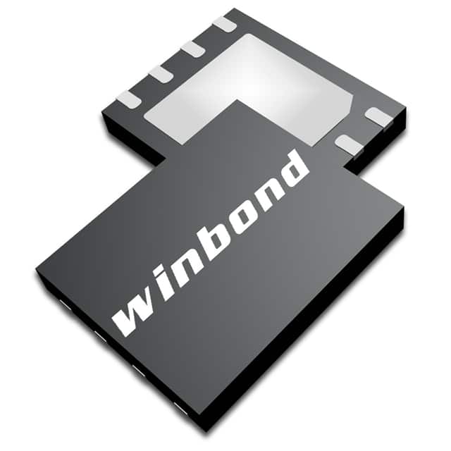
- Part No.:
- W971GG8NB-18I TR
- Manufacturer:
- Winbond Electronics Corporation
- Category:
- Memory
- Package:
- 60-VFBGA
- Datasheet:
-
 W971GG8NB-18I TR.pdf
- Description:
- IC DRAM 1GBIT SSTL 18 60VFBGA
- Quantity:
- Payment:

- Shipping:

Inventory:3,707
Please send an inquiry. Send us your inquiry, and we will respond immediately.
Product details
Overview
W971GG8NB-18I TR from Winbond is a 1G-bit DDR2 SDRAM organized as 16M × 8 banks × 8 bits, supporting DDR2-1066 (6-6-6) operation at 533 MHz clock frequency with CAS Latency 3–7, 1.8 V ±0.1 V supply, and industrial temperature range (−40°C to +95°C). It serves as main memory in embedded networking and industrial control systems requiring reliable high-bandwidth data buffering.
For engineers reviewing the W971GG8NB-18I TR datasheet, W971GG8NB-18I TR pinout, W971GG8NB-18I TR application, or W971GG8NB-18I TR equivalent, this page delivers verified DDR2 timing parameters, ball-level I/O mapping, OCD/ODT configuration details, and JEDEC-compliant thermal and electrical specifications for system-level signal integrity and power design.
Technical Context
This DDR2 SDRAM implements a double-data-rate architecture synchronized to differential CLK/CLK inputs, with DLL-aligned DQ/DQS timing and source-synchronous read/write strobing. It supports programmable additive latency (AL = 0–2), burst lengths of 4 or 8, and bi-directional DQS/DQS differential strobes edge-aligned on reads and center-aligned on writes.
Functional operation includes auto-precharge, self-refresh, precharged/active power-down modes, and on-die termination (ODT) controlled via dedicated ODT pin and EMR(1) settings. Off-chip driver (OCD) impedance calibration is supported through extended mode register commands with A9/A8/A7 address sequencing.
Key Specifications
| Parameter | Value and Actual Design Meaning |
|---|---|
| Memory Density | 1 G-bit (16,777,216 words × 8 banks × 8 bits) |
| Data Rate | 1066 Mbps (DDR2-1066, 533 MHz clock, tCK = 1.875 ns min @ CL=6) |
| Supply Voltage | VDD/VDDQ/VDDL = 1.8 V ± 0.1 V - requires tight regulation for SSTL_18 interface compliance |
| Operating Temperature | −40°C ≤ TCASE ≤ +95°C - qualified for industrial environments without derating |
| CAS Latency | Programmable CL = 3, 4, 5, 6, or 7 - determines minimum read access delay relative to command |
| Burst Length | Configurable BL = 4 or 8 - defines number of consecutive data transfers per READ/WRITE command |
| Refresh Interval | tREFI = 7.8 μs max (≤85°C), 3.9 μs max (85–95°C) - mandates doubled refresh rate above 85°C |
| Power Consumption | IDD0 ≤ 60 mA (active-precharge), IDD6 ≤ 8 mA (self-refresh) - enables low-power idle states |
Pinout & Package
Packaged in 60-ball Window BGA (WBGA), 8 mm × 9.5 mm × 1.0 mm, RoHS-compliant lead-free construction.
| Pin/Terminal | Circuit Role | Design Meaning |
|---|---|---|
| A0–A13 | Address Input | Row/column address bus; A10 controls auto-precharge enable during READ/WRITE |
| BA0–BA2 | Bank Select | 3-bit bank address for concurrent bank activation and command targeting |
| DQ0–DQ7 | Data I/O | 8-bit bidirectional data bus compliant with SSTL_18; requires matched trace routing |
| DQS / DQS | Differential Data Strobe | Source-synchronous strobe; edge-aligned with read data, center-aligned with write data |
| CLK / CLK | Differential Clock Input | Primary timing reference; all commands latched at crossing of CLK rising and CLK falling edges |
| CS, RAS, CAS, WE | Command Inputs | JEDEC-standard command encoding; CS enables rank selection in multi-rank systems |
| ODT | On-Die Termination Control | Active-HIGH signal enabling internal termination resistors for stub-free point-to-point topology |
| CKE | Clock Enable | Gates internal clocking; LOW disables DLL and enters power-down states |
| DM/RDQS | Data Mask / Read Strobe | Write data mask input sampled on both DQS edges; RDQS function enabled via EMR(1)[A11] |
| VREF | Input Reference Voltage | Mid-supply reference (VDDQ/2 ±300 mV) for SSTL_18 input threshold stability |
Key Features
| Feature | Design Value |
|---|---|
| OCD Impedance Calibration | Programmable off-chip driver output impedance via EMR(1) sequence - improves signal integrity across PCB trace variations |
| On-Die Termination (ODT) | Dynamically configurable termination resistance (75 Ω / 150 Ω) controlled by ODT pin - eliminates external termination components |
| Posted CAS with AL | Additive latency (AL = 0–2) decouples command bus occupancy from data return timing - increases command bandwidth efficiency |
| Dual-Power Domains | Separate VDDQ/VSSQ and VDDL/VSSDL supplies - isolates I/O noise from core/DLL circuitry for jitter reduction |
| Self-Refresh Mode | Autonomous refresh at <8 mA current draw - maintains data retention during host processor sleep or power gating |
| Industrial Temp Grade | Guaranteed operation from −40°C to +95°C with full AC/DC specs - suitable for fanless industrial controllers and telecom line cards |
Applications
| Industrial PLC Memory Buffer | Network Switch Packet Buffer |
|---|---|
Use Scenario: Real-time motion control logic in programmable logic controllers requires deterministic memory access with minimal latency variation under thermal stress. IC Role / Device Role / Timing Role: Primary working memory storing program state, I/O mapping tables, and cyclic process data with DDR2-1066 bandwidth. Use Value: Industrial temperature rating (−40°C to +95°C) and 6-6-6 timing ensure consistent tRCD/tRP/tRC margins across ambient extremes without firmware throttling. |
Use Scenario: Layer-2/Layer-3 Ethernet switches buffer ingress/egress packet queues in high-throughput forwarding pipelines. IC Role / Device Role / Timing Role: High-speed packet buffer interfacing directly to MAC-layer SerDes PHYs via SSTL_18 I/O. Use Value: Differential DQS strobing and OCD-calibrated drive strength maintain signal integrity at 533 MHz clock rates across 4+ inch PCB traces. |
| Medical Imaging Subsystem RAM | Automotive ADAS Camera Interface |
Use Scenario: Ultrasound and digital X-ray subsystems require burst-mode frame buffering with guaranteed data retention during intermittent power cycling. IC Role / Device Role / Timing Role: Frame buffer memory supporting burst reads/writes with auto-precharge and self-refresh for standby power savings. Use Value: Self-refresh current ≤8 mA at 95°C enables >24-hour data retention during equipment standby without auxiliary power. |
Use Scenario: Surround-view camera fusion ECUs aggregate multiple 1080p video streams for real-time stitching and object detection. IC Role / Device Role / Timing Role: Low-latency memory for intermediate frame storage between image sensor interface and GPU/NPU processing blocks. Use Value: Programmable CAS latency (CL=3–7) and posted CAS allow tuning for optimal throughput vs. latency trade-off in vision pipeline stages. |
Equivalent & Alternatives
The following parts are listed as comparable options for similar DDR2 SDRAM applications.
| Alternative Part | Technical Difference | Application Difference | Selection Advice |
|---|---|---|---|
| MT47H128M8HQ-37E:C | 1 G-bit DDR2-800 (CL=5, tCK=2.5 ns), 60-ball FBGA, −40°C to +95°C | Lower bandwidth (800 Mbps), higher tRCD/tRP (12.5 ns), no OCD calibration | Preferred where thermal margin exceeds timing margin and board layout lacks DQS routing complexity |
| IS42S16160F-6BLI | 256 M-bit DDR2-667 (CL=5), 60-ball FBGA, −40°C to +85°C | ¼ density, lower speed grade (667 Mbps), narrower temp range, no ODT pin control | Suitable for cost-sensitive designs with reduced memory footprint and relaxed bandwidth requirements |
Compared with MT47H128M8HQ-37E:C and IS42S16160F-6BLI, W971GG8NB-18I TR delivers 33% higher bandwidth, on-die termination control via dedicated pin, and OCD calibration for dynamic drive strength tuning - critical for high-reliability industrial and automotive memory interfaces.
Availability
W971GG8NB-18I TR is available at Aetrix Electronics and suitable for industrial PLCs, network packet buffers, medical imaging subsystems, and automotive ADAS camera interfaces requiring stable component supply across extended temperature ranges and long production lifecycles.
Supply support for W971GG8NB-18I TR includes scheduled delivery planning, volume procurement assistance, BOM continuity management, traceable sourcing, and lifecycle availability coordination for OEM customers, industrial embedded developers, connected-device designers, and electronics production programs.
Manufacturer
Winbond Electronics is a Taiwan-based semiconductor company specializing in specialty memory solutions including NOR/NAND Flash, SRAM, and DDR SDRAM for industrial, automotive, and communications markets.
The W971GG8NB series belongs to Winbond's industrial-grade DDR2 SDRAM product line, designed specifically for applications demanding extended temperature operation, JEDEC-compliant reliability, and robust signal integrity in space-constrained embedded systems.
FAQ
What is the maximum clock frequency supported by W971GG8NB-18I TR?
W971GG8NB-18I TR supports DDR2-1066 operation with a 533 MHz clock frequency (tCK = 1.875 ns minimum at CL=6). This speed grade is validated across the full industrial temperature range (−40°C to +95°C) and complies with JEDEC DDR2 specification 6-6-6 timing parameters including tRCD, tRP, and tRC.
Does W971GG8NB-18I TR support on-die termination (ODT)?
Yes, W971GG8NB-18I TR supports on-die termination via the dedicated ODT pin and EMR(1) configuration. When ODT is asserted HIGH, internal termination resistors (75 Ω or 150 Ω) are enabled on DQ/DQS lines - eliminating need for external termination and improving signal integrity in point-to-point topologies.
How is OCD calibration performed on W971GG8NB-18I TR?
OCD calibration on W971GG8NB-18I TR is executed via a defined EMR(1) command sequence using address pins A9/A8/A7. The process adjusts off-chip driver output impedance to match PCB trace characteristics, and must be completed within 200 clock cycles after DLL reset during initialization - as specified in the W971GG8NB-18I TR datasheet section 8.1.
What package type and dimensions does W971GG8NB-18I TR use?
W971GG8NB-18I TR uses a 60-ball Window BGA (WBGA) package measuring 8 mm × 9.5 mm × 1.0 mm. It features lead-free, RoHS-compliant construction with separate VDDQ/VSSQ and VDDL/VSSDL power domains to isolate I/O noise from core logic and DLL circuitry.
Can W971GG8NB-18I TR operate in self-refresh mode at 95°C?
Yes, W971GG8NB-18I TR supports self-refresh mode at up to +95°C with IDD6 ≤ 8 mA. At temperatures above 85°C, the device requires doubled refresh frequency (tREFI = 3.9 µs) enabled via A7=1 in EMR(2), ensuring data retention without host intervention during thermal stress conditions.
W971GG8NB-18I TR Specifications
- Product attributes
- Attribute value
- Manufacturer:
- Winbond Electronics Corporation
- Series:
- -
- Package/Case:
- 60-VFBGA
- Packaging:
- Tape & Reel (TR)
- Product Status:
- Active
- Programmable:
- Not Verified
- Memory Type:
- Volatile
- Memory Format:
- DRAM
- Technology:
- SDRAM - DDR2
- Memory Size:
- 1Gbit
- Memory Organization:
- 128M x 8
- Memory Interface:
- SSTL_18
- Clock Frequency:
- 533 MHz
- Write Cycle Time - Word, Page:
- 15ns
- Access Time:
- 58.125 ns
- Voltage - Supply:
- 1.7V ~ 1.9V
- Operating Temperature:
- -40°C ~ 95°C (TC)
- Grade:
- -
- Qualification:
- -
- Mounting Type:
- Surface Mount
- Supplier Device Package:
- 60-VFBGA (8x9.5)
W971GG8NB-18I TR FAQ
1.How can I place an order for W971GG8NB-18I TR through Aetrix?
Please submit a Request for Quotation (RFQ) for W971GG8NB-18I TR on Aetrix. Our sales agent will provide a competitive quotation and guide you through the order confirmation once you accept the terms.
2.Are the price and stock information for W971GG8NB-18I TR reliable?
The price and inventory of W971GG8NB-18I TR are updated periodically and may fluctuate due to market conditions. Stock and pricing data are typically refreshed every 24 hours. Quotation validity for W971GG8NB-18I TR is usually 5 days.
3.What payment methods are accepted for W971GG8NB-18I TR?
We accept Wire Transfer, PayPal, Credit Card, Western Union, MoneyGram, and Escrow for W971GG8NB-18I TR transactions.
Note: Certain payment methods may incur a processing fee.
4.How is shipping managed for W971GG8NB-18I TR?
W971GG8NB-18I TR orders can be shipped via leading logistics carriers, including DHL, UPS, FedEx, TNT, or Registered Mail.
Once your W971GG8NB-18I TR order is processed, you will receive an email with the shipment details and tracking number.
Note: Tracking information may take up to 24 hours to appear. Express delivery typically takes 3–5 business days.
5.How can I obtain technical support or documentation for W971GG8NB-18I TR?
For technical support, including W971GG8NB-18I TR datasheets, pinout diagrams, or application guidance, please contact our engineering support team. They can provide detailed documentation and assistance for your W971GG8NB-18I TR requirements.
6.How does Aetrix verify that W971GG8NB-18I TR is sourced from the original manufacturer or authorized distributors?
All W971GG8NB-18I TR products on Aetrix are procured from qualified distributors and authorized channels. Our dedicated quality assurance team conducts strict verification, including traceability checks and, if necessary, third-party testing. This ensures that W971GG8NB-18I TR meets industry standards.
7.What is the process for return or replacement of W971GG8NB-18I TR?
All W971GG8NB-18I TR units undergo pre-shipment inspection (PSI). If there is an issue with W971GG8NB-18I TR, returns or replacements are accepted under the following conditions:
1.Quantity discrepancies, incorrect items, or visible external defects (such as breakage or corrosion), acknowledged by Aetrix.
2.The issue is reported within 90 days of delivery.
3.The W971GG8NB-18I TR part is unused and in its original packaging.
Return procedure for W971GG8NB-18I TR:
1.Submit a request within 90 days.
2.Obtain a Return Material Authorization (RMA) from Aetrix.
W971GG8NB-18I TR Tags

-
M24C02-WMN6TP
STMicroelectronics

-
AT24C02C-XHM-T
Microchip Technology

-
AT21CS01-STUM10-T
Microchip Technology

-
AT24C02C-SSHM-T
Microchip Technology

-
24LC01BT-I/OT
Microchip Technology

-
M24C02-FMC6TG
STMicroelectronics
-
AT24CS02-SSHM-T
Microchip Technology

-
93LC46BT-I/OT
Microchip Technology
-
AT24C04C-SSHM-T
Microchip Technology

-
24LC01BT-I/SN
Microchip Technology
-
24AA02UIDT-I/OT
Microchip Technology

-
AT24C08C-STUM-T
Microchip Technology
Tech Hub

Counterfeit components can hide behind convincing markings and passing basic function tests. This engineering reference covers source traceability, external inspection, X-ray, XRF, electrical testing, …

A practical engineering and sourcing framework covering lifecycle verification, lifetime-buy calculations, replacement qualification, supplier checks and counterfeit-risk controls.

TTL and CMOS logic families differ in thresholds, loading, output drive, power and timing. This engineering guide compares 74HC and 74HCT, calculates noise margins and checks 3.3 V/5 V compatibility.

A practical engineering guide to 3.3V and 5V logic compatibility, input thresholds, resistor dividers, translator ICs, MOSFET level shifting, I2C pull-ups, timing limits and power-sequencing risks.

The 74HC595 uses push-pull logic outputs, while the TPIC6B595 uses 50 V open-drain DMOS sinks for higher-power loads. This guide compares timing, current limits, 3.3 V interfacing, load wiring, thermal…

The 74HC595 converts serial data into eight stable parallel outputs. This guide covers pin functions, shift and storage timing, OE and MR behavior, drive-current limits, cascading, voltage compatibilit…

A technical comparison of level-sensitive latches and edge-triggered flip-flops, covering timing windows, setup and hold limits, master–slave operation, time borrowing, race-through, HDL inference and…

A D latch stores one bit while Enable controls when data can pass. This reference covers gate-level operation, truth tables, transparency, setup and hold timing, LE versus OE, common ICs and practical …

An SR latch stores one bit through cross-coupled feedback. This engineering reference covers NOR and NAND implementations, truth tables, forbidden-state recovery, gated operation, switch debouncing, fa…

Latch circuits retain one bit through feedback. This technical reference covers SR and D latches, truth tables, transparency, timing limits, latch-versus-flip-flop behavior, applications and common log…


