
 My Inquiry
 My Account


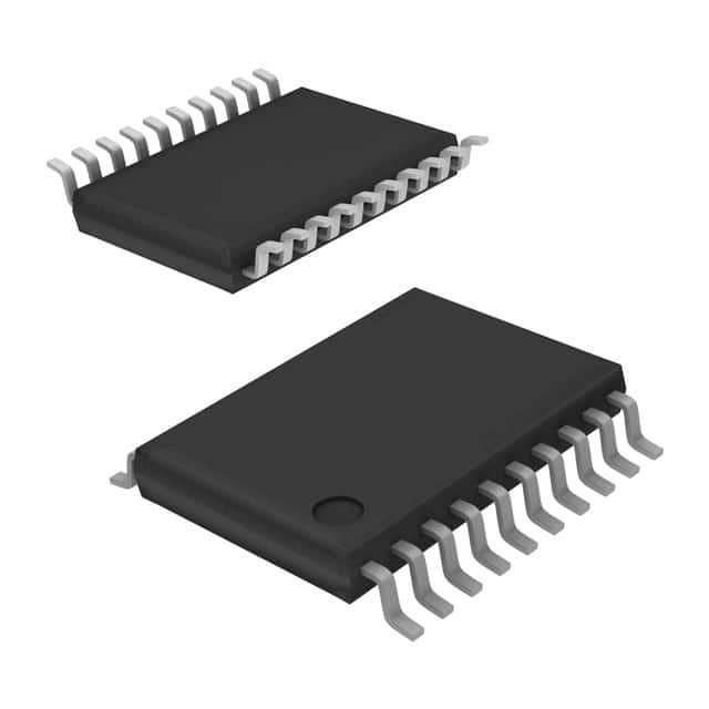
Renesas X95840WV20I-2.7
- Part No.:
- X95840WV20I-2.7
- Manufacturer:
- Renesas
- Category:
- Digital Potentiometers
- Package:
- 20-TSSOP (0.173", 4.40mm Width)
- Datasheet:
-
 X95840WV20I-2.7.pdf
- Description:
- IC DGT POT 10KOHM 256TAP 20TSSOP
- Quantity:
- Payment:

- Shipping:

Inventory:4,882
Please send an inquiry. Send us your inquiry, and we will respond immediately.
Product details
Overview
X95840WV20I-2.7 from Intersil is a quad digital controlled potentiometer (XDCP™) IC with I²C interface, 256-tap resolution, 10kΩ end-to-end resistance, and 20-lead TSSOP package. It operates from 2.7V to 5.5V, delivers <5µA standby current, and integrates non-volatile initial value registers for power-up wiper recall-used in precision analog trimming, sensor calibration, and programmable gain control.
For engineers reviewing the X95840WV20I-2.7 datasheet, X95840WV20I-2.7 pinout, X95840WV20I-2.7 application, or X95840WV20I-2.7 equivalent, key selection criteria include I²C address configurability (A0–A2), hardware write protection (WP), wiper resistance (70Ω typ.), and guaranteed monotonicity in both voltage divider and rheostat modes across industrial temperature range (–40°C to +85°C).
Technical Context
The X95840WV20I-2.7 implements four independent digitally controlled potentiometers using resistor ladders and CMOS switches, each controlled by an 8-bit volatile wiper register (WR) and backed by a non-volatile initial value register (IVR). At power-up, IVR contents are loaded into WRs, defaulting to mid-scale (0x80) if unprogrammed.
Its I²C slave interface supports standard-mode (400kHz) operation with three address pins (A0–A2), enabling up to eight devices on one bus. Write protection is enforced via active-low WP pin, and non-volatile writes require STOP condition initiation with internal 12–20ms self-timed cycle.
Key Specifications
| Parameter | Value and Actual Design Meaning |
|---|---|
| Total Resistance | 10kΩ - defines maximum analog impedance between RH and RL terminals; determines current-handling capability and voltage-divider scaling factor. |
| Resolution | 256 taps (0.4% per step) - enables fine-grained analog adjustment with ±1 LSB integral non-linearity in voltage divider mode. |
| Wiper Resistance | 70Ω typical at 3.3V - limits signal path insertion loss and thermal noise contribution in precision DC/low-frequency applications. |
| Supply Range | 2.7V to 5.5V - ensures compatibility with 3.3V and 5V logic domains and mixed-supply systems without level-shifting. |
| Standby Current | <5µA max at 5.5V - enables battery-powered or energy-sensitive designs where potentiometer idle power must be minimized. |
| I²C Clock Frequency | 400kHz - supports fast configuration updates without requiring high-speed MCU peripherals or custom timing firmware. |
| Temperature Range | –40°C to +85°C - validated for industrial-grade reliability with ±4 ppm/°C ratiometric tempco in voltage divider mode. |
Pinout & Package
Package: 20-lead Thin Shrink Small Outline Package (TSSOP), RoHS-compliant, body dimensions 6.5mm × 4.4mm × 1.2mm (D × E1 × A2), 0.65mm lead pitch.
| Pin/Terminal | Circuit Role | Design Meaning |
|---|---|---|
| RH3, RH2, RH1, RH0 | High terminal of DCP3–DCP0 | Fixed voltage reference point for each potentiometer; connects to VCC or signal source in voltage divider configuration. |
| RL3, RL2, RL1, RL0 | Low terminal of DCP3–DCP0 | Fixed ground or return reference; forms resistive divider leg with corresponding RH pin. |
| RW3, RW2, RW1, RW0 | Wiper terminal of DCP3–DCP0 | Adjustable output node; position set by 8-bit WR; used as variable voltage tap or adjustable resistance endpoint. |
| SDA, SCL | I²C bidirectional data/clock | Standard open-drain interface; requires external pull-ups; supports multi-device addressing via A0–A2. |
| A0, A1, A2 | I²C device address inputs | Three binary address bits; configure slave address (1010xx0/1) to support up to eight X95840 devices on one bus. |
| WP | Hardware write protect | Active-low pin; disables all I²C write operations (volatile and non-volatile) when pulled low-prevents accidental register corruption. |
| VCC, GND | Power supply and ground | Single 2.7–5.5V supply; decoupling capacitor recommended near VCC pin for noise immunity during wiper transitions. |
Key Features
| Feature | Design Value |
|---|---|
| Quad integration | Four independent 10kΩ DCPs in one 20-pin TSSOP - reduces board area vs. discrete potentiometers and eliminates inter-pot matching drift. |
| Non-volatile wiper recall | IVRs retain user-defined startup positions for all four DCPs - eliminates need for MCU initialization code or external EEPROM storage. |
| Monotonic performance | DNL ≤ ±0.5 LSB in both voltage divider and rheostat modes - guarantees no output glitches or direction reversals during wiper sweeps. |
| Low-power standby | ISB ≤ 5µA at 5.5V - enables always-on analog tuning in portable instrumentation without measurable battery drain. |
| Robust EEPROM endurance | 150,000 write cycles per register with 50-year data retention at ≤75°C - supports field recalibration over full product lifecycle. |
Applications
| Audio Signal Level Control | Sensor Offset Calibration |
|---|---|
Use Scenario: Adjusting gain and balance in professional audio mixers with remote digital control. IC Role / Device Role / Timing Role: Quad DCP acts as four independent programmable attenuators in analog signal paths before ADC stages. Use Value: Enables precise, repeatable, and noise-immune volume/balance settings without mechanical wear or manual trimmer access. | Use Scenario: Compensating zero-point drift in bridge-based pressure sensors across temperature. IC Role / Device Role / Timing Role: One DCP injects calibrated offset voltage into sensor amplifier feedback loop; others tune gain and reference. Use Value: Achieves <±0.5 LSB offset correction stability over –40°C to +85°C using factory-trimmed IVR values. |
| Programmable Power Supply Feedback | Industrial PLC Analog I/O Scaling |
Use Scenario: Dynamically adjusting output voltage of isolated DC-DC converters in adaptive power systems. IC Role / Device Role / Timing Role: DCP replaces fixed resistor in TL431 shunt regulator feedback divider to enable software-controlled VOUT. Use Value: Supports remote reconfiguration of supply rails without hardware change; 10kΩ resistance matches common optocoupler bias requirements. | Use Scenario: Scaling 4–20mA transmitter outputs to match varying input ranges of PLC analog input modules. IC Role / Device Role / Timing Role: Two DCPs configure gain and offset in precision op-amp conditioning circuitry for current-to-voltage conversion. Use Value: Eliminates manual potentiometer adjustments during commissioning; enables auto-calibration via HART or Modbus commands. |
Equivalent & Alternatives
The following parts are listed as comparable options for similar digitally controlled potentiometer applications.
| Alternative Part | Technical Difference | Application Difference | Selection Advice |
|---|---|---|---|
| AD5242BRUZ10 | 2-channel, 10kΩ, I²C interface, 24-lead TSSOP; no hardware WP pin; 100k-cycle EEPROM endurance. | Lacks quad integration and dedicated write protection; requires two devices for four-channel use. | Select when dual-channel density suffices and WP functionality is managed externally. |
| MCP4641T-103E/ST | Quad 10kΩ DCP, SPI interface, 20-lead TSSOP; 12-bit resolution; 200k-cycle EEPROM; no built-in IVR power-up recall. | Requires SPI host and explicit initialization sequence at boot; higher resolution but no automatic restore. | Select when SPI is preferred and MCU firmware can manage wiper initialization reliably. |
Compared with AD5242BRUZ10 and MCP4641T-103E/ST, the X95840WV20I-2.7 uniquely combines quad channel count, hardware write protection, automatic IVR-to-WR power-up loading, and industrial temperature-rated EEPROM in a single 20-pin I²C package-reducing BOM count and simplifying firmware for embedded analog tuning.
Availability
X95840WV20I-2.7 is available at Aetrix Electronics and suitable for audio signal conditioning, sensor calibration, programmable power supplies, and industrial analog I/O scaling requiring stable component supply and long-term traceability.
Supply support for X95840WV20I-2.7 includes scheduled delivery planning, volume procurement assistance, BOM continuity management, traceable sourcing, and lifecycle availability coordination for OEM customers, industrial embedded developers, connected-device designers, and electronics production programs.
Manufacturer
Intersil Corporation (now part of Renesas Electronics) is a U.S.-based analog and mixed-signal semiconductor company focused on power management, precision analog, and interface solutions.
The X95840 family was designed specifically for replacing mechanical potentiometers in industrial, test equipment, and communications systems where programmable, non-volatile, and low-noise analog adjustment is required.
FAQ
What is the default wiper position of the X95840WV20I-2.7 at power-up?
At power-up, the X95840WV20I-2.7 loads the contents of its four non-volatile Initial Value Registers (IVRs) into the corresponding volatile Wiper Registers (WRs). If unprogrammed, the factory-default IVR value is 0x80 (128 decimal), placing each wiper at mid-scale between RH and RL terminals. This behavior is guaranteed across the full –40°C to +85°C operating range and requires no external initialization.
Does the X95840WV20I-2.7 support true 4-wire (Kelvin) connections for precision rheostat use?
No, the X95840WV20I-2.7 does not support 4-wire Kelvin sensing. Each DCP has only three terminals (RH, RL, RW); the wiper resistance (70Ω typ.) is inherent to the CMOS switch architecture and contributes directly to measurement error in 2-terminal rheostat configurations. For high-accuracy current-setting applications, design margins must account for this wiper resistance variation across temperature and supply voltage.
Can the X95840WV20I-2.7 be used with 1.8V I²C buses?
No, the X95840WV20I-2.7 is not compatible with 1.8V I²C buses. Its absolute minimum VCC is 2.7V, and its I²C input thresholds (VIH = 0.7×VCC, VIL = 0.3×VCC) require VCC ≥ 2.7V to meet standard I²C logic levels. Operating below 2.7V violates recommended conditions and may cause unreliable communication or register corruption.
How does hardware write protection (WP pin) affect non-volatile versus volatile register access on the X95840WV20I-2.7?
When the WP pin is pulled low, the X95840WV20I-2.7 ignores all I²C write operations-including writes to volatile Wiper Registers (WRs) and non-volatile Initial Value Registers (IVRs). The device responds with no ACK and remains in standby. Read operations remain fully functional regardless of WP state, allowing safe monitoring of wiper positions and register contents without risk of unintended modification.
What is the maximum capacitive load the X95840WV20I-2.7 SDA/SCL lines can drive per the datasheet?
The X95840WV20I-2.7 specifies a total capacitive loading limit of 400pF for SDA and SCL lines combined (Cb ≤ 400pF). This includes on-chip pin capacitance (10pF) plus all PCB trace and external device contributions. Exceeding 400pF increases rise/fall times beyond specification (tR/tF ≤ 250ns), risking I²C timing violations-especially at 400kHz. External pull-up resistors must be scaled accordingly (e.g., ~2.2kΩ for 400pF).
X95840WV20I-2.7 Specifications
- Product attributes
- Attribute value
- Manufacturer:
- Renesas
- Series:
- XDCP™
- Package/Case:
- 20-TSSOP (0.173", 4.40mm Width)
- Packaging:
- Tube
- Product Status:
- Obsolete
- Programmable:
- Not Verified
- Taper:
- Linear
- Configuration:
- Potentiometer
- Number of Circuits:
- 4
- Number of Taps:
- 256
- Resistance (Ohms):
- 10k
- Interface:
- I2C
- Memory Type:
- Non-Volatile
- Voltage - Supply:
- 2.7V ~ 5.5V
- Features:
- Selectable Address
- Tolerance:
- ±20%
- Temperature Coefficient (Typ):
- ±45ppm/°C
- Mounting Type:
- Surface Mount
- Grade:
- -
- Qualification:
- -
- Supplier Device Package:
- 20-TSSOP
- Operating Temperature:
- -40°C ~ 85°C
- Resistance - Wiper (Ohms) (Typ):
- 70
X95840WV20I-2.7 FAQ
1.How can I place an order for X95840WV20I-2.7 through Aetrix?
Please submit a Request for Quotation (RFQ) for X95840WV20I-2.7 on Aetrix. Our sales agent will provide a competitive quotation and guide you through the order confirmation once you accept the terms.
2.Are the price and stock information for X95840WV20I-2.7 reliable?
The price and inventory of X95840WV20I-2.7 are updated periodically and may fluctuate due to market conditions. Stock and pricing data are typically refreshed every 24 hours. Quotation validity for X95840WV20I-2.7 is usually 5 days.
3.What payment methods are accepted for X95840WV20I-2.7?
We accept Wire Transfer, PayPal, Credit Card, Western Union, MoneyGram, and Escrow for X95840WV20I-2.7 transactions.
Note: Certain payment methods may incur a processing fee.
4.How is shipping managed for X95840WV20I-2.7?
X95840WV20I-2.7 orders can be shipped via leading logistics carriers, including DHL, UPS, FedEx, TNT, or Registered Mail.
Once your X95840WV20I-2.7 order is processed, you will receive an email with the shipment details and tracking number.
Note: Tracking information may take up to 24 hours to appear. Express delivery typically takes 3–5 business days.
5.How can I obtain technical support or documentation for X95840WV20I-2.7?
For technical support, including X95840WV20I-2.7 datasheets, pinout diagrams, or application guidance, please contact our engineering support team. They can provide detailed documentation and assistance for your X95840WV20I-2.7 requirements.
6.How does Aetrix verify that X95840WV20I-2.7 is sourced from the original manufacturer or authorized distributors?
All X95840WV20I-2.7 products on Aetrix are procured from qualified distributors and authorized channels. Our dedicated quality assurance team conducts strict verification, including traceability checks and, if necessary, third-party testing. This ensures that X95840WV20I-2.7 meets industry standards.
7.What is the process for return or replacement of X95840WV20I-2.7?
All X95840WV20I-2.7 units undergo pre-shipment inspection (PSI). If there is an issue with X95840WV20I-2.7, returns or replacements are accepted under the following conditions:
1.Quantity discrepancies, incorrect items, or visible external defects (such as breakage or corrosion), acknowledged by Aetrix.
2.The issue is reported within 90 days of delivery.
3.The X95840WV20I-2.7 part is unused and in its original packaging.
Return procedure for X95840WV20I-2.7:
1.Submit a request within 90 days.
2.Obtain a Return Material Authorization (RMA) from Aetrix.
X95840WV20I-2.7 Tags
-
MCP4018T-103E/LT
Microchip Technology
-
MCP4018T-503E/LT
Microchip Technology

-
MCP4011T-103E/SN
Microchip Technology
-
MCP4018T-104E/LT
Microchip Technology
-
MCP4017T-503E/LT
Microchip Technology
-
MCP4018T-502E/LT
Microchip Technology
-
MCP4017T-103E/LT
Microchip Technology

-
MCP4531T-103E/MF
Microchip Technology
-
MCP4021T-202E/SN
Microchip Technology

-
MCP4023T-103E/CH
Microchip Technology
-
MCP4022T-503E/CH
Microchip Technology

-
MCP4551T-502E/MS
Microchip Technology
Tech Hub

TTL and CMOS logic families differ in thresholds, loading, output drive, power and timing. This engineering guide compares 74HC and 74HCT, calculates noise margins and checks 3.3 V/5 V compatibility.

A practical engineering guide to 3.3V and 5V logic compatibility, input thresholds, resistor dividers, translator ICs, MOSFET level shifting, I2C pull-ups, timing limits and power-sequencing risks.

The 74HC595 uses push-pull logic outputs, while the TPIC6B595 uses 50 V open-drain DMOS sinks for higher-power loads. This guide compares timing, current limits, 3.3 V interfacing, load wiring, thermal…

The 74HC595 converts serial data into eight stable parallel outputs. This guide covers pin functions, shift and storage timing, OE and MR behavior, drive-current limits, cascading, voltage compatibilit…

A technical comparison of level-sensitive latches and edge-triggered flip-flops, covering timing windows, setup and hold limits, master–slave operation, time borrowing, race-through, HDL inference and…

A D latch stores one bit while Enable controls when data can pass. This reference covers gate-level operation, truth tables, transparency, setup and hold timing, LE versus OE, common ICs and practical …

An SR latch stores one bit through cross-coupled feedback. This engineering reference covers NOR and NAND implementations, truth tables, forbidden-state recovery, gated operation, switch debouncing, fa…

Latch circuits retain one bit through feedback. This technical reference covers SR and D latches, truth tables, transparency, timing limits, latch-versus-flip-flop behavior, applications and common log…

An engineering guide to LED driver operation, constant-current and constant-voltage outputs, linear and switching topologies, dimming, IC selection, calculations, replacement compatibility, and fault c…

Operational amplifier guide covering op amp basics, feedback, ideal vs real op amps, common configurations, buffer circuits, offset, bias current, gain-bandwidth, slew rate, rail-to-rail limits and sel…


