
 My Inquiry
 My Account


Renesas X9C104P
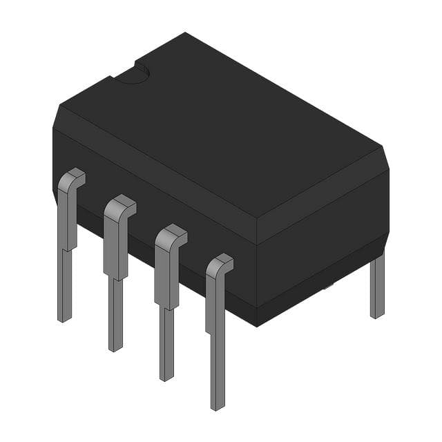
- Part No.:
- X9C104P
- Manufacturer:
- Renesas
- Category:
- Digital Potentiometers
- Package:
- 8-DIP (0.300", 7.62mm)
- Datasheet:
-
 X9C104P.pdf
- Description:
- IC DGTL POT 100KOHM 100TAP 8DIP
- Quantity:
- Payment:

- Shipping:

Inventory:2,929
Please send an inquiry. Send us your inquiry, and we will respond immediately.
Product details
Overview
X9C104P from Renesas Electronics is a digitally controlled potentiometer (XDCP™) with 100-kΩ end-to-end resistance, 100 wiper tap points, nonvolatile wiper position storage, ±5V terminal voltage rating, and 3mA max active supply current. It functions as a solid-state three-terminal potentiometer or two-terminal variable resistor in precision analog trimming applications requiring power-cycle retention.
For engineers reviewing the X9C104P datasheet, X9C104P pinout, X9C104P application, or X9C104P equivalent, this device supports stable analog parameter adjustment in industrial control loops, sensor calibration circuits, and programmable gain stages where mechanical potentiometer wear, drift, or manual access are unacceptable.
Technical Context
The X9C104P implements a 99-element resistor array with make-before-break wiper switching, controlled via a negative-edge-triggered three-wire interface (CS, U/D, INC). Its 7-bit up/down counter drives a decoder selecting one of 100 discrete tap positions, with wiper resistance typically 40 Ω.
Nonvolatile memory stores the last wiper position at power-down and recalls it on VCC ramp-up (tPU ≤ 500 µs), while internal charge pump enables ±5V analog signal handling with single 5V supply. Absolute linearity is ±1 MI (±1% of RTOTAL), and ratiometric temperature coefficient is ±20 ppm/°C.
Key Specifications
| Parameter | Value and Actual Design Meaning |
|---|---|
| End-to-End Resistance | 100 kΩ ±20% - defines full-scale analog range for voltage divider or current-limiting configurations |
| Wiper Tap Points | 100 positions - provides 1% resolution steps across resistance range for fine-grained digital control |
| Terminal Voltage Range | ±5 V - supports bipolar signal conditioning without external level-shifting circuitry |
| Supply Voltage | 5 V ±10% - compatible with standard TTL/CMOS logic rails and eliminates need for auxiliary supplies |
| Active Supply Current | ≤3 mA - enables low-power operation in battery-backed or energy-constrained systems |
| Nonvolatile Retention | 100 years - ensures factory-trimmed or user-calibrated settings persist over product lifetime |
| Temperature Range | −40°C to +85°C - qualified for industrial-grade embedded environments without derating |
Pinout & Package
Package: 8-lead PDIP (MDP0031), RoHS-compliant, through-hole wave-solder compatible only.
| Pin/Terminal | Circuit Role | Design Meaning |
|---|---|---|
| 1 INC | Increment clock input | Negative-edge-triggered control signal; toggling moves wiper one step in direction set by U/D |
| 2 U/D | Up/Down direction control | Logic level determines wiper movement direction during each INC edge; held stable during increment |
| 3 VH/RH | High-side fixed terminal | Analog terminal with −5 V to +5 V rating; polarity label reflects wiper motion direction, not voltage potential |
| 4 VSS | Ground reference | System ground return for digital control and analog terminals; must be connected before applying analog signals |
| 5 VW/RW | Wiper output terminal | Movable analog node with typical 40 Ω series resistance; connects to one of 100 tap points in resistor array |
| 6 VL/RL | Low-side fixed terminal | Analog terminal with −5 V to +5 V rating; labeled relative to U/D-selected wiper travel direction |
| 7 CS | Chip select | Active-low enable; HIGH transition with INC = HIGH initiates nonvolatile store; LOW enables real-time wiper control |
| 8 VCC | Positive supply | 5 V ±10% digital/analog supply; powers internal logic, charge pump, and resistor array biasing |
Key Features
| Feature | Design Value |
|---|---|
| Solid-state construction | Eliminates mechanical wear, contact bounce, and vibration sensitivity inherent in rotary potentiometers |
| Three-wire serial interface | Requires only CS, U/D, and INC signals-no clock or data lines-reducing MCU GPIO overhead and PCB routing complexity |
| Nonvolatile wiper storage | Retains last-set position across power cycles without external EEPROM or backup power circuitry |
| Temperature-compensated array | ±20 ppm/°C ratiometric TC ensures stable voltage division ratio across industrial temperature range |
| Make-before-break switching | Prevents open-circuit transients during wiper stepping-critical for maintaining continuity in feedback paths |
Applications
| Industrial Sensor Calibration | Programmable Gain Amplifier |
|---|---|
|
Use Scenario: Calibrating offset and span of pressure or temperature transducers in field-deployed instrumentation. IC Role / Device Role / Timing Role: Two-terminal variable resistor in bridge nulling or amplifier feedback path to adjust zero-point and full-scale output. Use Value: Enables automated factory calibration and field recalibration via microcontroller without opening enclosure or replacing components. |
Use Scenario: Setting precise closed-loop gain in analog signal conditioning for data acquisition front-ends. IC Role / Device Role / Timing Role: Three-terminal potentiometer configured as voltage divider controlling op-amp feedback network. Use Value: Provides 1% resolution gain adjustment with power-cycle persistence-eliminating manual trimpots and associated calibration logs. |
| Laser Diode Bias Control | Audio Tone Stack Trimming |
|
Use Scenario: Fine-tuning bias current in laser driver circuits to maintain constant optical output across temperature. IC Role / Device Role / Timing Role: Two-terminal variable resistor in current-setting path of constant-current source. Use Value: Delivers stable, drift-free bias point using nonvolatile setting-avoids thermal drift-induced output power variation. |
Use Scenario: Digitally adjusting bass/mid/treble response curves in professional audio mixing consoles. IC Role / Device Role / Timing Role: Three-terminal potentiometer in passive RC tone network with wiper as signal tap point. Use Value: Allows recallable EQ presets and remote adjustment via control bus-replacing multiple mechanical pots and switch banks. |
Equivalent & Alternatives
The following parts are listed as comparable options for similar digitally controlled potentiometer applications.
| Alternative Part | Technical Difference | Application Difference | Selection Advice |
|---|---|---|---|
| AD5204BRZ10 | Quad 10-kΩ channel, SPI interface, 256 taps, 3.3/5 V supply | Higher resolution (0.4% vs 1%), but lower resistance value and quad-channel architecture requires redesign | Select when multi-channel trimming or finer resolution is required; not drop-in due to different pinout and protocol |
| MCP41010-I/P | Single 10-kΩ channel, SPI interface, 256 taps, 2.7–5.5 V supply | Lower end-to-end resistance, SPI-based command structure, no built-in nonvolatile store on power cycle | Choose for SPI-native systems needing higher resolution; requires external memory or firmware save routine for persistence |
Compared with X9C104P, AD5204BRZ10 offers greater channel density and resolution but lacks direct 100-kΩ match and requires board-level SPI integration, while MCP41010-I/P provides finer granularity but mandates software-managed nonvolatile storage-neither replicates the X9C104P's self-contained 100-kΩ, 100-tap, auto-recall functionality in a PDIP package.
Availability
X9C104P is available at Aetrix Electronics and suitable for industrial sensor calibration, programmable gain amplifiers, laser diode bias control, and audio tone stack trimming requiring stable component supply with long-term lifecycle support.
Supply support for X9C104P includes scheduled delivery planning, volume procurement assistance, BOM continuity management, traceable sourcing, and lifecycle availability coordination for OEM customers, industrial embedded developers, connected-device designers, and electronics production programs.
Manufacturer
Renesas Electronics is a global semiconductor leader delivering microcontrollers, analog, power, and connectivity solutions for industrial, automotive, and infrastructure markets.
The X9C104P belongs to Renesas' XDCP™ digitally controlled potentiometer family, designed specifically for replacing mechanical trimmers in analog signal-path applications demanding reliability, programmability, and nonvolatile setting retention.
FAQ
What is the maximum allowable voltage across the VH/RH and VL/RL terminals for the X9C104P?
The X9C104P specifies a maximum ΔV = |VH/RH − VL/RL| of 10 V. This means the absolute voltage difference between its high-side and low-side fixed terminals must not exceed 10 V under any operating condition. Exceeding this limit risks permanent damage to the internal resistor array or switching elements, as confirmed in the Absolute Maximum Ratings table on page 4 of FN8222 Rev 4.00.
Does the X9C104P retain its wiper position after power removal, and how is that achieved?
Yes, the X9C104P retains its wiper position after power removal using on-chip nonvolatile memory. When CS transitions HIGH while INC is also HIGH, the current 7-bit counter value is written to EEPROM-like memory. Upon subsequent power-up, once VCC reaches its final value, the stored value is automatically recalled and applied to the wiper decoder-ensuring the X9C104P resumes operation at the last saved position without host intervention.
Can the X9C104P operate with analog signals outside the 0–5 V range?
Yes, the X9C104P supports analog terminal voltages from −5 V to +5 V on both VH/RH and VL/RL pins, enabling true bipolar operation. Its internal charge pump generates necessary bias for this extended range while accepting only a single 5 V supply on VCC. However, the voltage difference between VH/RH and VL/RL must remain ≤10 V, and all analog signals must stay within the specified −5 V to +5 V bounds relative to VSS.
What is the wiper resistance specification for the X9C104P, and why does it matter in circuit design?
The X9C104P has a typical wiper resistance (RW) of 40 Ω, with a maximum of 100 Ω per Electrical Specifications table (page 4). This series resistance directly impacts accuracy in low-impedance voltage divider or current-sensing applications-especially when the load impedance is comparable to RW. Designers must include RW in gain error calculations and verify that wiper current remains within ±4.4 mA limits to avoid nonlinearities or heating effects.
Is the X9C104P pin-compatible with other members of the X9Cxxx family, such as X9C103P or X9C503P?
Yes, the X9C104P shares identical pinout, package (8-lead PDIP or SOIC), and interface timing with X9C102P, X9C103P, and X9C503P. The only functional differences are end-to-end resistance values (1kΩ, 10kΩ, 100kΩ, 50kΩ respectively) and corresponding power ratings. This allows direct substitution in existing layouts when resistance value and power dissipation requirements align-verified across Ordering Information and Pin Descriptions sections of FN8222 Rev 4.00.
X9C104P Specifications
- Product attributes
- Attribute value
- Manufacturer:
- Renesas
- Series:
- XDCP™
- Package/Case:
- 8-DIP (0.300", 7.62mm)
- Packaging:
- Tube
- Product Status:
- Obsolete
- Programmable:
- Not Verified
- Taper:
- Linear
- Configuration:
- Potentiometer
- Number of Circuits:
- 1
- Number of Taps:
- 100
- Resistance (Ohms):
- 100k
- Interface:
- Up/Down (U/D, INC, CS)
- Memory Type:
- Non-Volatile
- Voltage - Supply:
- 5V
- Features:
- -
- Tolerance:
- ±20%
- Temperature Coefficient (Typ):
- ±300ppm/°C
- Mounting Type:
- Through Hole
- Grade:
- -
- Qualification:
- -
- Supplier Device Package:
- 8-PDIP
- Operating Temperature:
- 0°C ~ 70°C
- Resistance - Wiper (Ohms) (Typ):
- 40
X9C104P FAQ
1.How can I place an order for X9C104P through Aetrix?
Please submit a Request for Quotation (RFQ) for X9C104P on Aetrix. Our sales agent will provide a competitive quotation and guide you through the order confirmation once you accept the terms.
2.Are the price and stock information for X9C104P reliable?
The price and inventory of X9C104P are updated periodically and may fluctuate due to market conditions. Stock and pricing data are typically refreshed every 24 hours. Quotation validity for X9C104P is usually 5 days.
3.What payment methods are accepted for X9C104P?
We accept Wire Transfer, PayPal, Credit Card, Western Union, MoneyGram, and Escrow for X9C104P transactions.
Note: Certain payment methods may incur a processing fee.
4.How is shipping managed for X9C104P?
X9C104P orders can be shipped via leading logistics carriers, including DHL, UPS, FedEx, TNT, or Registered Mail.
Once your X9C104P order is processed, you will receive an email with the shipment details and tracking number.
Note: Tracking information may take up to 24 hours to appear. Express delivery typically takes 3–5 business days.
5.How can I obtain technical support or documentation for X9C104P?
For technical support, including X9C104P datasheets, pinout diagrams, or application guidance, please contact our engineering support team. They can provide detailed documentation and assistance for your X9C104P requirements.
6.How does Aetrix verify that X9C104P is sourced from the original manufacturer or authorized distributors?
All X9C104P products on Aetrix are procured from qualified distributors and authorized channels. Our dedicated quality assurance team conducts strict verification, including traceability checks and, if necessary, third-party testing. This ensures that X9C104P meets industry standards.
7.What is the process for return or replacement of X9C104P?
All X9C104P units undergo pre-shipment inspection (PSI). If there is an issue with X9C104P, returns or replacements are accepted under the following conditions:
1.Quantity discrepancies, incorrect items, or visible external defects (such as breakage or corrosion), acknowledged by Aetrix.
2.The issue is reported within 90 days of delivery.
3.The X9C104P part is unused and in its original packaging.
Return procedure for X9C104P:
1.Submit a request within 90 days.
2.Obtain a Return Material Authorization (RMA) from Aetrix.
X9C104P Tags
-
MCP4018T-103E/LT
Microchip Technology
-
MCP4018T-503E/LT
Microchip Technology

-
MCP4011T-103E/SN
Microchip Technology
-
MCP4018T-104E/LT
Microchip Technology
-
MCP4017T-503E/LT
Microchip Technology
-
MCP4018T-502E/LT
Microchip Technology
-
MCP4017T-103E/LT
Microchip Technology

-
MCP4531T-103E/MF
Microchip Technology
-
MCP4021T-202E/SN
Microchip Technology

-
MCP4023T-103E/CH
Microchip Technology
-
MCP4022T-503E/CH
Microchip Technology

-
MCP4551T-502E/MS
Microchip Technology
Tech Hub

TTL and CMOS logic families differ in thresholds, loading, output drive, power and timing. This engineering guide compares 74HC and 74HCT, calculates noise margins and checks 3.3 V/5 V compatibility.

A practical engineering guide to 3.3V and 5V logic compatibility, input thresholds, resistor dividers, translator ICs, MOSFET level shifting, I2C pull-ups, timing limits and power-sequencing risks.

The 74HC595 uses push-pull logic outputs, while the TPIC6B595 uses 50 V open-drain DMOS sinks for higher-power loads. This guide compares timing, current limits, 3.3 V interfacing, load wiring, thermal…

The 74HC595 converts serial data into eight stable parallel outputs. This guide covers pin functions, shift and storage timing, OE and MR behavior, drive-current limits, cascading, voltage compatibilit…

A technical comparison of level-sensitive latches and edge-triggered flip-flops, covering timing windows, setup and hold limits, master–slave operation, time borrowing, race-through, HDL inference and…

A D latch stores one bit while Enable controls when data can pass. This reference covers gate-level operation, truth tables, transparency, setup and hold timing, LE versus OE, common ICs and practical …

An SR latch stores one bit through cross-coupled feedback. This engineering reference covers NOR and NAND implementations, truth tables, forbidden-state recovery, gated operation, switch debouncing, fa…

Latch circuits retain one bit through feedback. This technical reference covers SR and D latches, truth tables, transparency, timing limits, latch-versus-flip-flop behavior, applications and common log…

An engineering guide to LED driver operation, constant-current and constant-voltage outputs, linear and switching topologies, dimming, IC selection, calculations, replacement compatibility, and fault c…

Operational amplifier guide covering op amp basics, feedback, ideal vs real op amps, common configurations, buffer circuits, offset, bias current, gain-bandwidth, slew rate, rail-to-rail limits and sel…


