
 My Inquiry
 My Account


AMD XC3130-4PQ100I
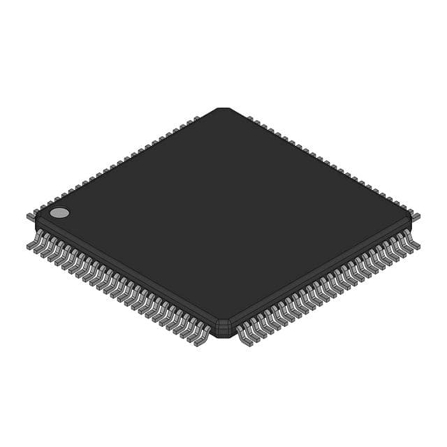
- Part No.:
- XC3130-4PQ100I
- Manufacturer:
- AMD
- Category:
- FPGAs (Field Programmable Gate Array)
- Package:
- 100-BQFP
- Datasheet:
-
 XC3130-4PQ100I.pdf
- Description:
- FPGA, 100 CLBS, 2K GATES
- Quantity:
- Payment:

- Shipping:

Inventory:4,229
Please send an inquiry. Send us your inquiry, and we will respond immediately.
Product details
Overview
XC3130-4PQ100I from Xilinx is a high-performance, 2,000-gate Field Programmable Gate Array (FPGA) in a 100-pin PQFP package, featuring a 10×10 Configurable Logic Block (CLB) array, 80 user I/Os, and guaranteed 370 MHz flip-flop toggle rates. It implements synchronous digital logic using static configuration memory, supports TTL/CMOS input thresholds, and integrates on-chip crystal oscillator amplifier for clock generation - used in legacy telecom interface controllers and industrial motion control logic.
For engineers reviewing the XC3130-4PQ100I datasheet, pinout, applications, or equivalent options, this page delivers verified architecture details, CLB-level timing parameters, I/O buffer slew-rate control behavior, Soft Startup initialization sequence, and pin-compatible alternatives for obsolescence-mitigated redesigns.
Technical Context
The XC3130-4PQ100I implements a regular, extendable FPGA architecture with three core configurable elements: a perimeter of programmable Input/Output Blocks (IOBs), a 10×10 core array of Configurable Logic Blocks (CLBs), and hierarchical interconnect resources including horizontal longlines, general-purpose metal grids, and direct CLB-to-CLB paths. Each CLB contains dual flip-flops, five logic inputs (A–E), programmable enable clock (EC), invertible clock (K), and asynchronous reset (RD).
Configuration is loaded via serial or parallel mode into distributed static memory cells; bitstream is compatible with XC3000A, XC3000L, and XC3100A families. The device features Soft Startup - slew-rate limiting all outputs during initial power-up - and error-checking of configuration bitstream stop bits to terminate invalid loads.
Key Specifications
| Parameter | Value and Actual Design Meaning |
|---|---|
| Logic Capacity | 2,000 system gates (1,500–2,000 typical range) |
| CLB Array Size | 10 × 10 = 100 CLBs; each CLB provides two flip-flops and combinatorial logic |
| User I/O Pins | 80 bidirectional pins with programmable TTL/CMOS thresholds and pull-up resistors |
| Toggle Rate | Guaranteed 370 MHz flip-flop toggle rate; enables >85 MHz system clock operation |
| Logic Delay | 1.55 ns minimum combinational delay (F/G path); independent of function complexity |
| Output Drive | 8 mA sink/source per I/O; supports direct TTL/CMOS fan-out without external buffers |
| Configuration Memory | 22,176-bit static RAM cell array; immune to alpha radiation and supply excursions |
Pinout & Package
XC3130-4PQ100I is housed in a 100-pin Plastic Quad Flat Package (PQFP) with 0.65 mm lead pitch, JEDEC MS-026 compliant. Package dimensions are 20.0 mm × 20.0 mm × 3.0 mm (L × W × H). Thermal resistance θJA = 45°C/W.
| Pin/Terminal | Circuit Role | Design Meaning |
|---|---|---|
| VCC | Power Supply | 5 V ±5% main supply for core and I/O; decoupling required at each corner |
| GND | Ground Reference | Dedicated ground pins distributed across all four sides for low-inductance return paths |
| RESET | Global Asynchronous Reset | Active-Low chip-wide reset; initializes all CLB and IOB flip-flops during configuration |
| INIT | Configuration Status | Open-drain output; pulled Low if bitstream error detected during load |
| CCLK | Configuration Clock | Input for serial configuration mode; drives internal shift register for bitstream loading |
| DIN | Serial Data Input | Primary serial configuration data input; synchronized to CCLK edge |
| I/O[0:79] | Programmable Bidirectional Interface | Each supports registered/direct input, registered/direct output, 3-state control, and slew-rate selection |
Key Features
| Feature | Design Value |
|---|---|
| Soft Startup | Automatically limits output slew rate at first activation post-configuration to prevent ground bounce across all 80 I/Os |
| Bitstream Error Checking | Verifies stop-bit positions in configuration data; asserts INIT Low on mismatch to halt invalid load |
| On-Chip Oscillator Amplifier | Allows direct connection of external crystal (1–20 MHz) to drive internal clock networks without external oscillator IC |
| Architecture Compatibility | Pin-out, bitstream, and software compatible with XC3000A, XC3000L, and XC3100A families for drop-in migration |
| CLB Flexibility | Each CLB supports dual independent 4-variable functions (F/G), single 5-variable function, or merged 6–7 variable logic via E-select mode |
Applications
| Telecom Line Interface Logic | Industrial Motion Controller |
|---|---|
Use Scenario: Implementing HDLC framing, CRC generation, and T1/E1 line timing recovery in legacy base station backplanes. IC Role / Device Role / Timing Role: Replaces discrete PALs and TTL glue logic; provides deterministic 1.55 ns combinatorial delay for synchronous bit-slicing and state-machine sequencing. Use Value: Eliminates board-level propagation skew between protocol engine and physical layer interface by integrating timing-critical paths within single-CLB logic blocks. | Use Scenario: Real-time interpolation and step/dir signal generation for multi-axis CNC machine tool controllers. IC Role / Device Role / Timing Role: Serves as deterministic servo loop coordinator; uses dual CLB flip-flops with shared RD and EC to synchronize position update cycles at 200 kHz. Use Value: Achieves sub-microsecond jitter on step pulses via direct CLB-to-IOB routing, avoiding PCB trace-length matching constraints. |
| Legacy Avionics Bus Bridge | Test Equipment Pattern Generator |
Use Scenario: Translating ARINC 429 data words to MIL-STD-1553B command/response frames in flight control subsystems. IC Role / Device Role / Timing Role: Acts as protocol-aware bridge; leverages on-chip crystal oscillator amplifier to derive synchronized 1 MHz and 4 MHz clocks from single 4 MHz crystal. Use Value: Reduces external clock tree components by 3, lowering EMI risk and qualification burden for DO-254 Level A hardware. | Use Scenario: Generating high-fidelity, multi-channel digital stimulus waveforms for ASIC validation benches. IC Role / Device Role / Timing Role: Functions as programmable pattern sequencer; uses 80 I/Os with 8 mA drive to directly drive DUT pins without level-shifting buffers. Use Value: Enables 370 MHz toggle capability to produce >185 MHz pseudo-random test vectors, exceeding requirements for 130 nm ASIC characterization. |
Equivalent & Alternatives
The following parts are listed as comparable options for similar FPGA logic implementation applications.
| Alternative Part | Technical Difference | Application Difference | Selection Advice |
|---|---|---|---|
| XC3130A-4PQ100C | Same architecture and pinout; commercial temperature grade (0°C to 70°C) vs. industrial (-40°C to +85°C) | Lacks extended thermal qualification; unsuitable for under-hood or factory-floor deployments | Select only for lab-bench or non-temperature-critical prototypes |
| XCV300-4PQ240C | Virtex-series successor; 300,000 system gates, 240-pin PQFP, 3.3 V core, no Soft Startup or bitstream error checking | Requires full RTL re-synthesis and new PCB layout due to different I/O structure and voltage levels | Use only for green-field designs where legacy compatibility is not required |
Compared with XC3130-4PQ100I, the XC3130A-4PQ100C offers identical functionality but lacks industrial temperature support, while the XCV300-4PQ240C provides vastly higher density and speed at the cost of architectural discontinuity, requiring complete design revalidation and no bitstream reuse.
Availability
XC3130-4PQ100I is available at Aetrix Electronics and suitable for legacy telecom infrastructure upgrades, industrial motion controller refurbishment, and avionics maintenance programs requiring stable component supply and long-term traceability.
Supply support for XC3130-4PQ100I includes scheduled delivery planning, volume procurement assistance, BOM continuity management, traceable sourcing, and lifecycle availability coordination for OEM customers, industrial embedded developers, connected-device designers, and electronics production programs.
Manufacturer
Xilinx, Inc. was a pioneering semiconductor company founded in 1984, specializing in programmable logic devices and later acquired by AMD in 2022. It developed the first commercial FPGA architecture and established industry standards for reconfigurable computing.
The XC3100A family - including XC3130-4PQ100I - was engineered as a performance-optimized extension of the XC3000A series, targeting high-speed digital control, protocol bridging, and real-time signal processing in systems demanding deterministic timing and field-upgradable logic.
FAQ
What is the operating voltage requirement for XC3130-4PQ100I?
The XC3130-4PQ100I requires a nominal 5.0 V ±5% supply on VCC. It is not compatible with 3.3 V operation - unlike the XC3130L variant. All I/Os are 5 V-tolerant and support TTL/CMOS threshold selection via configuration bits. Power integrity must be maintained with local 0.1 µF ceramic decoupling at each VCC pin, as specified in the November 1998 XC3000 Series datasheet.
Does XC3130-4PQ100I support in-system reprogramming?
Yes, XC3130-4PQ100I supports in-system reprogramming via its serial configuration interface using CCLK and DIN pins. Configuration can be reloaded without power cycling, enabling field logic updates. The device retains its programmed state only while powered; external PROM (e.g., XC1736) is required for automatic reload at power-up. Soft Startup and bitstream error checking remain active during each reconfiguration cycle.
What is the maximum number of user I/Os available on XC3130-4PQ100I?
XC3130-4PQ100I provides 80 user-configurable I/O pins in its 100-pin PQFP package. All 80 pins support bidirectional operation, programmable input thresholds (TTL or CMOS), optional internal pull-up resistors, and individually selectable slew-rate control. No I/Os are dedicated - every pin except VCC, GND, RESET, INIT, CCLK, and DIN is fully user-assignable.
How does Soft Startup function on XC3130-4PQ100I?
Soft Startup on XC3130-4PQ100I automatically limits the slew rate of all 80 I/O outputs during the first activation after configuration completes. This prevents simultaneous switching noise (SSN) and ground bounce that could destabilize adjacent circuitry. After startup, individual I/O slew rates revert to values set by configuration bits. The feature is hardware-enforced and requires no user code or external components.
Is XC3130-4PQ100I pin-compatible with other XC3000-series FPGAs?
Yes, XC3130-4PQ100I is 100% pin-out compatible with XC3030A-4PQ100I and XC3030L-4PQ100I in the same PQFP package. It shares identical mechanical footprint, power/ground pin locations, and I/O pin assignments. However, differences in configuration timing, drive strength (8 mA vs. 4 mA), and Soft Startup behavior require verification of timing closure and signal integrity in migrated designs.
XC3130-4PQ100I Specifications
- Product attributes
- Attribute value
- Manufacturer:
- AMD
- Series:
- XC3100
- Package/Case:
- 100-BQFP
- Packaging:
- Bulk
- Product Status:
- Active
- Programmable:
- Not Verified
- Number of LABs/CLBs:
- 100
- Number of Logic Elements/Cells:
- 100
- Total RAM Bits:
- 22176
- Number of I/O:
- 80
- Number of Gates:
- 2000
- Voltage - Supply:
- 4.5V ~ 5.5V
- Mounting Type:
- Surface Mount
- Operating Temperature:
- -40°C ~ 100°C (TJ)
- Grade:
- -
- Qualification:
- -
- Supplier Device Package:
- 100-PQFP (20x14)
XC3130-4PQ100I FAQ
1.How can I place an order for XC3130-4PQ100I through Aetrix?
Please submit a Request for Quotation (RFQ) for XC3130-4PQ100I on Aetrix. Our sales agent will provide a competitive quotation and guide you through the order confirmation once you accept the terms.
2.Are the price and stock information for XC3130-4PQ100I reliable?
The price and inventory of XC3130-4PQ100I are updated periodically and may fluctuate due to market conditions. Stock and pricing data are typically refreshed every 24 hours. Quotation validity for XC3130-4PQ100I is usually 5 days.
3.What payment methods are accepted for XC3130-4PQ100I?
We accept Wire Transfer, PayPal, Credit Card, Western Union, MoneyGram, and Escrow for XC3130-4PQ100I transactions.
Note: Certain payment methods may incur a processing fee.
4.How is shipping managed for XC3130-4PQ100I?
XC3130-4PQ100I orders can be shipped via leading logistics carriers, including DHL, UPS, FedEx, TNT, or Registered Mail.
Once your XC3130-4PQ100I order is processed, you will receive an email with the shipment details and tracking number.
Note: Tracking information may take up to 24 hours to appear. Express delivery typically takes 3–5 business days.
5.How can I obtain technical support or documentation for XC3130-4PQ100I?
For technical support, including XC3130-4PQ100I datasheets, pinout diagrams, or application guidance, please contact our engineering support team. They can provide detailed documentation and assistance for your XC3130-4PQ100I requirements.
6.How does Aetrix verify that XC3130-4PQ100I is sourced from the original manufacturer or authorized distributors?
All XC3130-4PQ100I products on Aetrix are procured from qualified distributors and authorized channels. Our dedicated quality assurance team conducts strict verification, including traceability checks and, if necessary, third-party testing. This ensures that XC3130-4PQ100I meets industry standards.
7.What is the process for return or replacement of XC3130-4PQ100I?
All XC3130-4PQ100I units undergo pre-shipment inspection (PSI). If there is an issue with XC3130-4PQ100I, returns or replacements are accepted under the following conditions:
1.Quantity discrepancies, incorrect items, or visible external defects (such as breakage or corrosion), acknowledged by Aetrix.
2.The issue is reported within 90 days of delivery.
3.The XC3130-4PQ100I part is unused and in its original packaging.
Return procedure for XC3130-4PQ100I:
1.Submit a request within 90 days.
2.Obtain a Return Material Authorization (RMA) from Aetrix.
XC3130-4PQ100I Tags
-
ICE40LP384-SG32
Lattice Semiconductor Corporation
-
ICE40UL640-CM36AI
Lattice Semiconductor Corporation
-
ICE40UL1K-CM36AI
Lattice Semiconductor Corporation
-
LCMXO2-256HC-4SG32C
Lattice Semiconductor Corporation
-
10M02DCV36C8G
Intel
-
LCMXO2-256HC-4SG32I
Lattice Semiconductor Corporation
-
ICE5LP1K-SG48ITR
Lattice Semiconductor Corporation
-
ICE40LP1K-CM36
Lattice Semiconductor Corporation
-
LCMXO2-256ZE-1SG32I
Lattice Semiconductor Corporation
-
LCMXO2-256HC-4SG48I
Lattice Semiconductor Corporation
-
ICE40LP1K-CM81
Lattice Semiconductor Corporation

-
T20W80I4
Efinix, Inc.
Tech Hub

A practical engineering and sourcing framework covering lifecycle verification, lifetime-buy calculations, replacement qualification, supplier checks and counterfeit-risk controls.

TTL and CMOS logic families differ in thresholds, loading, output drive, power and timing. This engineering guide compares 74HC and 74HCT, calculates noise margins and checks 3.3 V/5 V compatibility.

A practical engineering guide to 3.3V and 5V logic compatibility, input thresholds, resistor dividers, translator ICs, MOSFET level shifting, I2C pull-ups, timing limits and power-sequencing risks.

The 74HC595 uses push-pull logic outputs, while the TPIC6B595 uses 50 V open-drain DMOS sinks for higher-power loads. This guide compares timing, current limits, 3.3 V interfacing, load wiring, thermal…

The 74HC595 converts serial data into eight stable parallel outputs. This guide covers pin functions, shift and storage timing, OE and MR behavior, drive-current limits, cascading, voltage compatibilit…

A technical comparison of level-sensitive latches and edge-triggered flip-flops, covering timing windows, setup and hold limits, master–slave operation, time borrowing, race-through, HDL inference and…

A D latch stores one bit while Enable controls when data can pass. This reference covers gate-level operation, truth tables, transparency, setup and hold timing, LE versus OE, common ICs and practical …

An SR latch stores one bit through cross-coupled feedback. This engineering reference covers NOR and NAND implementations, truth tables, forbidden-state recovery, gated operation, switch debouncing, fa…

Latch circuits retain one bit through feedback. This technical reference covers SR and D latches, truth tables, transparency, timing limits, latch-versus-flip-flop behavior, applications and common log…

An engineering guide to LED driver operation, constant-current and constant-voltage outputs, linear and switching topologies, dimming, IC selection, calculations, replacement compatibility, and fault c…


