
 My Inquiry
 My Account


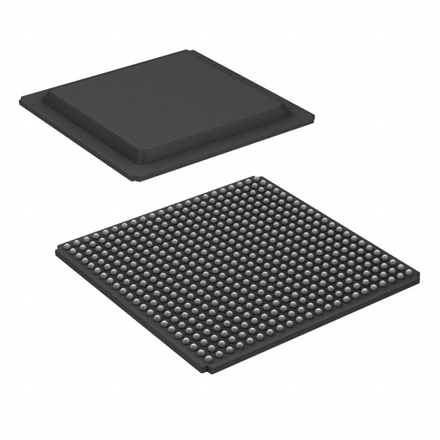
AMD XC7A15T-1FGG484C
- Part No.:
- XC7A15T-1FGG484C
- Manufacturer:
- AMD
- Category:
- FPGAs (Field Programmable Gate Array)
- Package:
- 484-BBGA
- Datasheet:
-
 XC7A15T-1FGG484C.pdf
- Description:
- IC FPGA 250 I/O 484FBGA
- Quantity:
- Payment:

- Shipping:

Inventory:1,630
Please send an inquiry. Send us your inquiry, and we will respond immediately.
Product details
Overview
XC7A15T-1FGG484C from AMD (formerly Xilinx) is a Spartan-7 FPGA featuring 15,840 logic cells, 1.2 Mb of block RAM, and 120 DSP slices, packaged in a 484-pin Fine-Pitch Flip-Chip BGA (FFG484). It supports I/O standards up to 1.8 V and operates at -40°C to +100°C junction temperature, targeting cost-sensitive industrial control and embedded vision interfaces.
For engineers reviewing the XC7A15T-1FGG484C datasheet, pinout, applications, or equivalent options, key selection criteria include logic density, I/O voltage flexibility, thermal rating, and availability of transceiver-capable banks for high-speed serial links.
Technical Context
The XC7A15T-1FGG484C implements a 28 nm HKMG process-based architecture with configurable logic blocks (CLBs), distributed RAM, shift registers, and dedicated carry chains. It integrates SelectIO™ technology supporting LVCMOS, LVDS, SSTL, and HSTL I/O standards across 12 I/O banks.
It includes dual-register flip-flops per LUT, clock management tiles with MMCM and PLL support, and configuration via JTAG, SPI, or master/slave serial modes. No integrated transceivers - serial interface capability relies on I/O bank–based LVDS or differential signaling.
Key Specifications
| Parameter | Value and Actual Design Meaning |
|---|---|
| Logic Cells | 15,840 - determines maximum combinational/sequential logic capacity for custom digital functions |
| Block RAM | 1.2 Mb - supports on-chip data buffering, FIFOs, and small lookup tables without external memory |
| DSP Slices | 120 - enables fixed-point arithmetic acceleration for filtering, motor control, and sensor fusion |
| I/O Banks | 12 - allows independent voltage domain assignment per bank for mixed-voltage system interfacing |
| Max I/O Count | 210 - defines number of user-accessible pins available for peripheral, sensor, or interface connectivity |
| Operating Temp | -40°C to +100°C - qualifies for extended industrial environments without derating |
| Configuration Mode | Master SPI, Slave Serial, JTAG - supports field-upgradable bitstreams and boundary-scan testing |
Pinout & Package
XC7A15T-1FGG484C is housed in a 22×22 mm, 0.8 mm pitch, 484-ball Fine-Pitch Flip-Chip BGA (package code FGG484) with 210 user I/O pins distributed across 12 banks. Power and ground balls are arranged per Xilinx SP701 package drawing revision D.
| Pin/Terminal | Circuit Role | Design Meaning |
|---|---|---|
| G19 | VCCO_0 | I/O bank 0 power supply - sets output voltage level for all pins in bank 0 |
| P17 | IO_L1P_T0_0 | Differential input pair positive - supports LVDS, TMDS, or RSDS signaling in bank 0 |
| T16 | IO_L1N_T0_0 | Differential input pair negative - must be routed with matched length to P17 for signal integrity |
| R15 | CLKIN1_M2C | Primary single-ended clock input - feeds MMCM for internal clock synthesis and phase alignment |
| W19 | M0 | Configuration mode select - low = master SPI, high = slave serial mode |
Key Features
| Feature | Design Value |
|---|---|
| UltraScale-inspired CLB architecture | 6-input LUTs with dual flip-flops enable high-density logic mapping and pipelining efficiency |
| SelectIO™ technology | Per-bank I/O voltage control (1.2–1.8 V) simplifies integration with mixed-voltage peripherals |
| Integrated clock management | MMCM + PLL provide sub-100 fs jitter performance and flexible frequency synthesis for timing-critical designs |
| Configurable I/O standards | Supports LVCMOS, LVDS, SSTL, HSTL, and MIPI D-PHY (in specific banks) for sensor and display interface reuse |
| Industrial temperature grade | Rated for operation up to +100°C junction temperature - eliminates need for thermal derating in fanless enclosures |
Applications
| Industrial PLC I/O Module | Embedded Vision Preprocessing Unit |
|---|---|
Use Scenario: Real-time digital input/output conditioning and protocol translation in modular automation controllers. IC Role / Device Role / Timing Role: FPGA fabric implements custom state machines, debounce logic, and fieldbus interface cores (e.g., Modbus RTU over RS-485). Use Value: 210 I/O pins and 12 independently powered banks allow direct connection to diverse sensors, actuators, and legacy fieldbus transceivers without level-shifter ICs. | Use Scenario: Pixel-level image correction and frame buffering before transmission to an SoC or GPU. IC Role / Device Role / Timing Role: XC7A15T-1FGG484C performs Bayer demosaicing, gamma correction, and line buffering using block RAM and DSP slices. Use Value: 1.2 Mb block RAM provides full-line storage for HD resolution (1280×720 @ 16-bit), eliminating external frame buffers and reducing latency. |
| Motor Control Feedback Interface | Test Equipment Digital Pattern Generator |
Use Scenario: Acquisition and preprocessing of encoder, resolver, and current-sense signals in servo drives. IC Role / Device Role / Timing Role: Dedicated logic handles quadrature decoding, sinc-filtering for sigma-delta ADCs, and PWM synchronization. Use Value: 120 DSP slices accelerate real-time current loop calculations; -40°C to +100°C rating ensures reliability inside sealed drive enclosures. | Use Scenario: Generation of synchronized multi-channel digital stimulus waveforms for PCB functional test. IC Role / Device Role / Timing Role: XC7A15T-1FGG484C configures parallel I/O banks as high-speed pattern ports with precise timing control via MMCM. Use Value: 210 user I/O pins support up to 128-bit wide parallel vectors; fine-grained clock phase adjustment enables <100 ps edge placement accuracy. |
Equivalent & Alternatives
The following parts are listed as comparable options for similar FPGA-based logic implementation applications.
| Alternative Part | Technical Difference | Application Difference | Selection Advice |
|---|---|---|---|
| XC7A35T-1FGG484C | 29,600 logic cells, 2.1 Mb BRAM, 210 DSP slices - higher density and memory capacity | Suitable for larger state machines or multi-channel processing where XC7A15T-1FGG484C reaches resource limits | Select when design requires >15K LUTs or >1.2 Mb on-chip memory without changing footprint |
| XC7A15T-2FGG484I | Same logic resources but -2 speed grade and industrial (-40°C to +100°C) vs. commercial (0°C to +85°C) temp grade | Required for designs needing guaranteed timing closure at higher clock frequencies or wider temperature range | Choose XC7A15T-2FGG484I only if timing analysis fails at 100 MHz+ or ambient exceeds +85°C |
Compared with XC7A15T-1FGG484C, XC7A35T-1FGG484C offers scalable logic headroom while sharing pinout and package, whereas XC7A15T-2FGG484I delivers tighter timing margins and broader thermal compliance - both require no PCB redesign but differ in cost, power, and timing validation effort.
Availability
XC7A15T-1FGG484C is available at Aetrix Electronics and suitable for industrial automation, embedded vision, and motor control applications requiring stable component supply, long-term lifecycle assurance, and traceable sourcing.
Supply support for XC7A15T-1FGG484C includes scheduled delivery planning, volume procurement assistance, BOM continuity management, traceable sourcing, and lifecycle availability coordination for OEM customers, industrial embedded developers, connected-device designers, and electronics production programs.
Manufacturer
AMD acquired Xilinx in 2022 and now develops adaptive computing platforms including FPGAs, adaptive SoCs, and AI engines for heterogeneous compute acceleration.
The Spartan-7 family, including XC7A15T-1FGG484C, was designed for cost-optimized, power-efficient logic implementation in industrial, automotive, and IoT edge systems with reliable long-lifecycle support.
FAQ
What is the maximum supported I/O standard voltage for XC7A15T-1FGG484C?
XC7A15T-1FGG484C supports I/O standards up to 1.8 V across its 12 I/O banks. Each bank can be independently configured for voltages from 1.2 V to 1.8 V, enabling direct interfacing with mixed-voltage peripherals such as 1.8 V sensors and 3.3 V legacy controllers - provided appropriate VCCO and reference voltage settings are applied per bank.
Does XC7A15T-1FGG484C include built-in high-speed transceivers?
No, XC7A15T-1FGG484C does not integrate multi-gigabit transceivers. High-speed serial communication must be implemented using SelectIO™-based differential standards (e.g., LVDS, TMDS) within I/O banks. For PCIe, Gigabit Ethernet, or USB 3.x physical layer support, external PHY devices or higher-tier Artix-7/FPGA families are required.
What configuration modes are supported by XC7A15T-1FGG484C?
XC7A15T-1FGG484C supports Master SPI, Slave Serial, and JTAG configuration modes. Master SPI enables standalone boot from external flash; Slave Serial allows bitstream loading from a host processor; JTAG is used for programming, debugging, and boundary-scan testing. Configuration mode is selected via M0–M2 pins during power-up.
Can XC7A15T-1FGG484C operate reliably at 100°C junction temperature?
Yes, XC7A15T-1FGG484C is rated for industrial temperature range (-40°C to +100°C) and qualified to operate continuously at 100°C junction temperature. Thermal design must ensure adequate PCB copper area, airflow, or heatsinking to maintain junction temperature within spec under worst-case power dissipation conditions.
How many block RAM primitives are available in XC7A15T-1FGG484C?
XC7A15T-1FGG484C contains 1.2 Mb of total block RAM, implemented as 80 x 18 Kb BRAM primitives. These can be configured as true dual-port RAM, ROM, or shift register memory, and are distributed across the FPGA fabric to minimize routing congestion and maximize utilization in data-path intensive designs.
XC7A15T-1FGG484C Specifications
- Product attributes
- Attribute value
- Manufacturer:
- AMD
- Series:
- Artix-7
- Package/Case:
- 484-BBGA
- Packaging:
- Tray
- Product Status:
- Active
- Programmable:
- Not Verified
- Number of LABs/CLBs:
- 1300
- Number of Logic Elements/Cells:
- 16640
- Total RAM Bits:
- 921600
- Number of I/O:
- 250
- Number of Gates:
- -
- Voltage - Supply:
- 0.95V ~ 1.05V
- Mounting Type:
- Surface Mount
- Operating Temperature:
- 0°C ~ 85°C (TJ)
- Grade:
- -
- Qualification:
- -
- Supplier Device Package:
- 484-FBGA (23x23)
XC7A15T-1FGG484C FAQ
1.How can I place an order for XC7A15T-1FGG484C through Aetrix?
Please submit a Request for Quotation (RFQ) for XC7A15T-1FGG484C on Aetrix. Our sales agent will provide a competitive quotation and guide you through the order confirmation once you accept the terms.
2.Are the price and stock information for XC7A15T-1FGG484C reliable?
The price and inventory of XC7A15T-1FGG484C are updated periodically and may fluctuate due to market conditions. Stock and pricing data are typically refreshed every 24 hours. Quotation validity for XC7A15T-1FGG484C is usually 5 days.
3.What payment methods are accepted for XC7A15T-1FGG484C?
We accept Wire Transfer, PayPal, Credit Card, Western Union, MoneyGram, and Escrow for XC7A15T-1FGG484C transactions.
Note: Certain payment methods may incur a processing fee.
4.How is shipping managed for XC7A15T-1FGG484C?
XC7A15T-1FGG484C orders can be shipped via leading logistics carriers, including DHL, UPS, FedEx, TNT, or Registered Mail.
Once your XC7A15T-1FGG484C order is processed, you will receive an email with the shipment details and tracking number.
Note: Tracking information may take up to 24 hours to appear. Express delivery typically takes 3–5 business days.
5.How can I obtain technical support or documentation for XC7A15T-1FGG484C?
For technical support, including XC7A15T-1FGG484C datasheets, pinout diagrams, or application guidance, please contact our engineering support team. They can provide detailed documentation and assistance for your XC7A15T-1FGG484C requirements.
6.How does Aetrix verify that XC7A15T-1FGG484C is sourced from the original manufacturer or authorized distributors?
All XC7A15T-1FGG484C products on Aetrix are procured from qualified distributors and authorized channels. Our dedicated quality assurance team conducts strict verification, including traceability checks and, if necessary, third-party testing. This ensures that XC7A15T-1FGG484C meets industry standards.
7.What is the process for return or replacement of XC7A15T-1FGG484C?
All XC7A15T-1FGG484C units undergo pre-shipment inspection (PSI). If there is an issue with XC7A15T-1FGG484C, returns or replacements are accepted under the following conditions:
1.Quantity discrepancies, incorrect items, or visible external defects (such as breakage or corrosion), acknowledged by Aetrix.
2.The issue is reported within 90 days of delivery.
3.The XC7A15T-1FGG484C part is unused and in its original packaging.
Return procedure for XC7A15T-1FGG484C:
1.Submit a request within 90 days.
2.Obtain a Return Material Authorization (RMA) from Aetrix.
XC7A15T-1FGG484C Tags
-
ICE40LP384-SG32
Lattice Semiconductor Corporation
-
ICE40UL640-CM36AI
Lattice Semiconductor Corporation
-
ICE40UL1K-CM36AI
Lattice Semiconductor Corporation
-
LCMXO2-256HC-4SG32C
Lattice Semiconductor Corporation
-
10M02DCV36C8G
Intel
-
LCMXO2-256HC-4SG32I
Lattice Semiconductor Corporation
-
ICE5LP1K-SG48ITR
Lattice Semiconductor Corporation
-
ICE40LP1K-CM36
Lattice Semiconductor Corporation
-
LCMXO2-256ZE-1SG32I
Lattice Semiconductor Corporation
-
LCMXO2-256HC-4SG48I
Lattice Semiconductor Corporation
-
ICE40LP1K-CM81
Lattice Semiconductor Corporation

-
T20W80I4
Efinix, Inc.
Tech Hub

A practical engineering and sourcing framework covering lifecycle verification, lifetime-buy calculations, replacement qualification, supplier checks and counterfeit-risk controls.

TTL and CMOS logic families differ in thresholds, loading, output drive, power and timing. This engineering guide compares 74HC and 74HCT, calculates noise margins and checks 3.3 V/5 V compatibility.

A practical engineering guide to 3.3V and 5V logic compatibility, input thresholds, resistor dividers, translator ICs, MOSFET level shifting, I2C pull-ups, timing limits and power-sequencing risks.

The 74HC595 uses push-pull logic outputs, while the TPIC6B595 uses 50 V open-drain DMOS sinks for higher-power loads. This guide compares timing, current limits, 3.3 V interfacing, load wiring, thermal…

The 74HC595 converts serial data into eight stable parallel outputs. This guide covers pin functions, shift and storage timing, OE and MR behavior, drive-current limits, cascading, voltage compatibilit…

A technical comparison of level-sensitive latches and edge-triggered flip-flops, covering timing windows, setup and hold limits, master–slave operation, time borrowing, race-through, HDL inference and…

A D latch stores one bit while Enable controls when data can pass. This reference covers gate-level operation, truth tables, transparency, setup and hold timing, LE versus OE, common ICs and practical …

An SR latch stores one bit through cross-coupled feedback. This engineering reference covers NOR and NAND implementations, truth tables, forbidden-state recovery, gated operation, switch debouncing, fa…

Latch circuits retain one bit through feedback. This technical reference covers SR and D latches, truth tables, transparency, timing limits, latch-versus-flip-flop behavior, applications and common log…

An engineering guide to LED driver operation, constant-current and constant-voltage outputs, linear and switching topologies, dimming, IC selection, calculations, replacement compatibility, and fault c…


