
 My Inquiry
 My Account


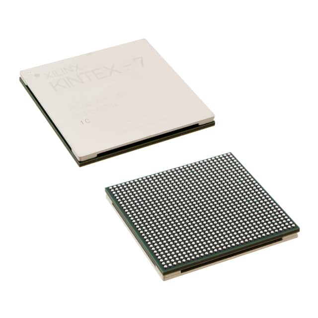
AMD XC7K325T-1FBG900C
- Part No.:
- XC7K325T-1FBG900C
- Manufacturer:
- AMD
- Category:
- FPGAs (Field Programmable Gate Array)
- Package:
- 900-BBGA, FCBGA
- Datasheet:
-
 XC7K325T-1FBG900C.pdf
- Description:
- IC FPGA 500 I/O 900FCBGA
- Quantity:
- Payment:

- Shipping:

Inventory:4,402
Please send an inquiry. Send us your inquiry, and we will respond immediately.
Product details
Overview
XC7K325T-1FBG900C from AMD is a Kintex-7 FPGA with 326,080 logic cells, 1,345 I/O pins, and 16.3 Mb of block RAM, configured in a 900-pin FCBGA package with 1.0V core voltage and -1 speed grade for high-performance wired infrastructure and test equipment applications.
For engineers reviewing the XC7K325T-1FBG900C datasheet, pinout, applications, or equivalent options, key selection criteria include I/O count, transceiver line rate (13.1 Gb/s), DSP slice count (840), and thermal performance in air-cooled 1U systems.
Technical Context
The XC7K325T-1FBG900C implements a 28 nm HKMG process architecture with integrated 6.6 Gb/s and 13.1 Gb/s multi-gigabit transceivers, supporting PCIe Gen3 x8, SATA 3.0, and SRIO 2.1 protocols. It includes 840 DSP48E1 slices for high-throughput filtering and FFT operations.
Configuration is performed via Master SPI or JTAG, with support for dual-boot and bitstream encryption using AES-256. The device operates across commercial temperature range (0°C to 85°C) and meets JESD8-12A I/O standards.
Key Specifications
| Parameter | Value and Actual Design Meaning |
|---|---|
| Logic Cells | 326,080 - supports complex digital signal processing pipelines with low-latency loop closure |
| Block RAM | 16.3 Mb - enables large on-chip buffering for video frame stores or protocol packet queues |
| Transceiver Line Rate | 13.1 Gb/s - delivers full-duplex 10G Ethernet PHY layer without external retimers |
| DSP Slices | 840 - provides 2,520 GMAC/s for real-time radar beamforming or software-defined radio modulation |
| I/O Pins | 1,345 - accommodates parallel DDR3/DDR4 memory interfaces plus multiple high-speed serial lanes |
| Core Voltage | 1.0 V - requires tightly regulated DC-DC supply with <±2% tolerance and <10 mV ripple |
Pinout & Package
XC7K325T-1FBG900C is housed in a 900-ball Fine-Pitch Column Grid Array (FCBGA) package with 31 × 31 mm body size, 1.0 mm ball pitch, and thermal lid for passive heat dissipation in conduction-cooled modules.
| Pin/Terminal | Circuit Role | Design Meaning |
|---|---|---|
| MIO[0:15] | Multiplexed I/O Bank | Configurable as SDIO, UART, SPI, or GPIO; supports 1.8V/3.3V I/O standards |
| GTXE2_CHANNEL | High-Speed Transceiver | Each pair supports 6.6–13.1 Gb/s serial links with built-in CDR and 8B/10B encoding |
| HP_IO_L[0:71] | High-Performance I/O Bank | Supports DDR3/DDR4 SDRAM interfaces up to 1,866 Mbps with dynamic calibration |
| VCCINT | Core Power Supply | Must be supplied at 1.0 V ±2% with dedicated low-ESR ceramic decoupling near each power ball |
| PROGRAM_B | Configuration Control | Active-low asynchronous reset that initiates reconfiguration from external flash or host processor |
Key Features
| Feature | Design Value |
|---|---|
| PCIe Gen3 x8 Endpoint | Integrated hard IP enables direct attachment to host CPU without bridge IC or firmware overhead |
| AES-256 Bitstream Encryption | Prevents reverse engineering and unauthorized configuration cloning in deployed field units |
| Dual-Boot Configuration Support | Allows fail-safe firmware updates by maintaining active and backup bitstreams in external flash |
| AXI4-Interconnect Fabric | Enables plug-and-play integration of custom IP blocks with guaranteed timing closure at 250 MHz |
| UltraScale-Compatible Toolflow | Shares Vivado design tools and constraint syntax with newer families, easing migration paths |
Applications
| Wireless Baseband Processing | Automated Test Equipment (ATE) |
|---|---|
Use Scenario: Real-time 5G NR physical layer processing including channel estimation, MIMO detection, and LDPC decoding. IC Role / Device Role / Timing Role: Primary programmable baseband processor implementing L1 stack functions with deterministic sub-microsecond latency. Use Value: 840 DSP slices and 13.1 Gb/s transceivers enable full-bandwidth 100 MHz 5G carrier processing within single device. | Use Scenario: High-channel-count parametric test instrumentation requiring synchronized analog stimulus and digital response capture. IC Role / Device Role / Timing Role: Timing and pattern generation engine synchronizing >128 DUT channels with <100 ps skew across backplane. Use Value: 1,345 I/O pins and deterministic routing allow simultaneous control of multiple instrument modules without external glue logic. |
| Optical Transport Networking | Medical Imaging Acceleration |
Use Scenario: OTN framer/mapper functionality in 100G/400G line cards handling OTU4/OTUCn encapsulation and FEC. IC Role / Device Role / Timing Role: Line-side packet processor interfacing directly to 100G coherent optical modules via CAUI-4. Use Value: Integrated 13.1 Gb/s transceivers and 16.3 Mb block RAM support full OTU4 frame buffering and scrambling in hardware. | Use Scenario: Real-time reconstruction pipeline for CT and MRI scanners requiring iterative back-projection and image denoising. IC Role / Device Role / Timing Role: Co-processor accelerating compute-intensive kernels while offloading host CPU and GPU resources. Use Value: 326,080 logic cells and AXI4 fabric enable concurrent execution of multiple reconstruction algorithms with DMA-controlled data flow. |
Equivalent & Alternatives
The following parts are listed as comparable options for similar FPGA-based signal processing applications.
| Alternative Part | Technical Difference | Application Difference | Selection Advice |
|---|---|---|---|
| XCKU040-2FFVA1156E | Higher logic density (503K LC), 16.3 Gb/s transceivers, but larger 1156-ball package and higher static power | Better suited for 400G crypto-accelerated switching where transceiver count exceeds XC7K325T capacity | Select when >24 GTY transceivers or >1000 GMAC/s throughput required |
| XC7K160T-2FBG676I | Fewer logic cells (162K), lower I/O count (500), same 13.1 Gb/s transceivers, industrial temp (-40°C to 100°C) | Targeted for ruggedized avionics data concentrators needing extended temperature operation | Choose for cost-sensitive, thermally constrained deployments where full XC7K325T resources are unused |
Compared with XC7K325T-1FBG900C, XCKU040 offers higher bandwidth and density at increased power and board area cost, while XC7K160T trades capacity for thermal robustness and lower BOM cost-enabling tiered system scaling without toolchain change.
Availability
XC7K325T-1FBG900C is available at Aetrix Electronics and suitable for wireless infrastructure, automated test equipment, and optical transport networking requiring stable component supply and long-term production continuity.
Supply support for XC7K325T-1FBG900C includes scheduled delivery planning, volume procurement assistance, BOM continuity management, traceable sourcing, and lifecycle availability coordination for OEM customers, industrial embedded developers, connected-device designers, and electronics production programs.
Manufacturer
AMD is a global semiconductor leader delivering adaptive computing solutions for data center, embedded, and client markets with focus on performance-per-watt efficiency.
The Kintex-7 family targets high-throughput, cost-sensitive applications demanding balanced logic, I/O, and DSP resources-optimized for wired communications, video processing, and industrial automation.
FAQ
What is the maximum supported DDR3 data rate for XC7K325T-1FBG900C?
The XC7K325T-1FBG900C supports DDR3 SDRAM interfaces up to 1,866 Mbps per pin using its HP I/O banks. This capability is validated with Micron MT41J256M16HA-125 and requires dynamic on-die termination calibration and write-leveling sequences implemented in the MIG IP core. XC7K325T-1FBG900C achieves this rate under commercial temperature conditions with proper PCB stack-up and matched trace lengths.
Does XC7K325T-1FBG900C support PCIe Gen3 x8 root complex functionality?
XC7K325T-1FBG900C implements PCIe Gen3 x8 endpoint functionality only-not root complex. Its integrated hard IP supports link training, transaction layer packet handling, and MSI-X interrupt generation as an endpoint device. To operate as a root complex, external switch or host bridge IC is required. XC7K325T-1FBG900C remains compatible with standard PCIe Gen3 x8 slots when configured as endpoint.
What configuration modes are supported by XC7K325T-1FBG900C?
XC7K325T-1FBG900C supports Master SPI, Slave SelectMAP, JTAG, and BPI configuration modes. Master SPI is most common for single-flash boot; JTAG is used for debugging and programming during development. Dual-boot capability allows two independent bitstreams stored in external flash, with PROGRAM_B and MODE pins selecting active image. XC7K325T-1FBG900C does not support slave serial mode.
Is XC7K325T-1FBG900C qualified for automotive applications?
No, XC7K325T-1FBG900C is rated for commercial temperature range (0°C to 85°C) and is not AEC-Q100 qualified. For automotive use, AMD offers the XA7K325T variant with extended temperature range (-40°C to 125°C) and additional reliability screening. XC7K325T-1FBG900C is intended for industrial, communications, and test equipment environments where ambient conditions remain within commercial spec.
What is the typical static power consumption of XC7K325T-1FBG900C at 25°C?
At 25°C ambient and 1.0 V core voltage, XC7K325T-1FBG900C exhibits typical static power consumption of 3.2 W in configuration mode with all I/Os tri-stated and no transceivers active. This value scales with junction temperature and voltage tolerance; actual system-level static power depends on I/O bank voltage settings, enabled clock networks, and unused logic retention states. XC7K325T-1FBG900C power estimates require XPE tool input with precise design utilization.
XC7K325T-1FBG900C Specifications
- Product attributes
- Attribute value
- Manufacturer:
- AMD
- Series:
- Kintex®-7
- Package/Case:
- 900-BBGA, FCBGA
- Packaging:
- Tray
- Product Status:
- Active
- Programmable:
- Not Verified
- Number of LABs/CLBs:
- 25475
- Number of Logic Elements/Cells:
- 326080
- Total RAM Bits:
- 16404480
- Number of I/O:
- 500
- Number of Gates:
- -
- Voltage - Supply:
- 0.97V ~ 1.03V
- Mounting Type:
- Surface Mount
- Operating Temperature:
- 0°C ~ 85°C (TJ)
- Grade:
- -
- Qualification:
- -
- Supplier Device Package:
- 900-FCBGA (31x31)
XC7K325T-1FBG900C FAQ
1.How can I place an order for XC7K325T-1FBG900C through Aetrix?
Please submit a Request for Quotation (RFQ) for XC7K325T-1FBG900C on Aetrix. Our sales agent will provide a competitive quotation and guide you through the order confirmation once you accept the terms.
2.Are the price and stock information for XC7K325T-1FBG900C reliable?
The price and inventory of XC7K325T-1FBG900C are updated periodically and may fluctuate due to market conditions. Stock and pricing data are typically refreshed every 24 hours. Quotation validity for XC7K325T-1FBG900C is usually 5 days.
3.What payment methods are accepted for XC7K325T-1FBG900C?
We accept Wire Transfer, PayPal, Credit Card, Western Union, MoneyGram, and Escrow for XC7K325T-1FBG900C transactions.
Note: Certain payment methods may incur a processing fee.
4.How is shipping managed for XC7K325T-1FBG900C?
XC7K325T-1FBG900C orders can be shipped via leading logistics carriers, including DHL, UPS, FedEx, TNT, or Registered Mail.
Once your XC7K325T-1FBG900C order is processed, you will receive an email with the shipment details and tracking number.
Note: Tracking information may take up to 24 hours to appear. Express delivery typically takes 3–5 business days.
5.How can I obtain technical support or documentation for XC7K325T-1FBG900C?
For technical support, including XC7K325T-1FBG900C datasheets, pinout diagrams, or application guidance, please contact our engineering support team. They can provide detailed documentation and assistance for your XC7K325T-1FBG900C requirements.
6.How does Aetrix verify that XC7K325T-1FBG900C is sourced from the original manufacturer or authorized distributors?
All XC7K325T-1FBG900C products on Aetrix are procured from qualified distributors and authorized channels. Our dedicated quality assurance team conducts strict verification, including traceability checks and, if necessary, third-party testing. This ensures that XC7K325T-1FBG900C meets industry standards.
7.What is the process for return or replacement of XC7K325T-1FBG900C?
All XC7K325T-1FBG900C units undergo pre-shipment inspection (PSI). If there is an issue with XC7K325T-1FBG900C, returns or replacements are accepted under the following conditions:
1.Quantity discrepancies, incorrect items, or visible external defects (such as breakage or corrosion), acknowledged by Aetrix.
2.The issue is reported within 90 days of delivery.
3.The XC7K325T-1FBG900C part is unused and in its original packaging.
Return procedure for XC7K325T-1FBG900C:
1.Submit a request within 90 days.
2.Obtain a Return Material Authorization (RMA) from Aetrix.
XC7K325T-1FBG900C Tags
-
ICE40LP384-SG32
Lattice Semiconductor Corporation
-
ICE40UL640-CM36AI
Lattice Semiconductor Corporation
-
ICE40UL1K-CM36AI
Lattice Semiconductor Corporation
-
LCMXO2-256HC-4SG32C
Lattice Semiconductor Corporation
-
10M02DCV36C8G
Intel
-
LCMXO2-256HC-4SG32I
Lattice Semiconductor Corporation
-
ICE5LP1K-SG48ITR
Lattice Semiconductor Corporation
-
ICE40LP1K-CM36
Lattice Semiconductor Corporation
-
LCMXO2-256ZE-1SG32I
Lattice Semiconductor Corporation
-
LCMXO2-256HC-4SG48I
Lattice Semiconductor Corporation
-
ICE40LP1K-CM81
Lattice Semiconductor Corporation

-
T20W80I4
Efinix, Inc.
Tech Hub

A practical engineering and sourcing framework covering lifecycle verification, lifetime-buy calculations, replacement qualification, supplier checks and counterfeit-risk controls.

TTL and CMOS logic families differ in thresholds, loading, output drive, power and timing. This engineering guide compares 74HC and 74HCT, calculates noise margins and checks 3.3 V/5 V compatibility.

A practical engineering guide to 3.3V and 5V logic compatibility, input thresholds, resistor dividers, translator ICs, MOSFET level shifting, I2C pull-ups, timing limits and power-sequencing risks.

The 74HC595 uses push-pull logic outputs, while the TPIC6B595 uses 50 V open-drain DMOS sinks for higher-power loads. This guide compares timing, current limits, 3.3 V interfacing, load wiring, thermal…

The 74HC595 converts serial data into eight stable parallel outputs. This guide covers pin functions, shift and storage timing, OE and MR behavior, drive-current limits, cascading, voltage compatibilit…

A technical comparison of level-sensitive latches and edge-triggered flip-flops, covering timing windows, setup and hold limits, master–slave operation, time borrowing, race-through, HDL inference and…

A D latch stores one bit while Enable controls when data can pass. This reference covers gate-level operation, truth tables, transparency, setup and hold timing, LE versus OE, common ICs and practical …

An SR latch stores one bit through cross-coupled feedback. This engineering reference covers NOR and NAND implementations, truth tables, forbidden-state recovery, gated operation, switch debouncing, fa…

Latch circuits retain one bit through feedback. This technical reference covers SR and D latches, truth tables, transparency, timing limits, latch-versus-flip-flop behavior, applications and common log…

An engineering guide to LED driver operation, constant-current and constant-voltage outputs, linear and switching topologies, dimming, IC selection, calculations, replacement compatibility, and fault c…


