
 My Inquiry
 My Account


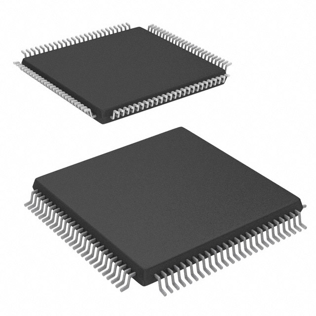
AMD XCS30-3VQ100C
- Part No.:
- XCS30-3VQ100C
- Manufacturer:
- AMD
- Category:
- FPGAs (Field Programmable Gate Array)
- Package:
- 100-TQFP
- Datasheet:
-
 XCS30-3VQ100C.pdf
- Description:
- IC FPGA 77 I/O 100VQFP
- Quantity:
- Payment:

- Shipping:

Inventory:2,498
Please send an inquiry. Send us your inquiry, and we will respond immediately.
Product details
Overview
XCS30-3VQ100C from AMD (formerly Xilinx) is a Spartan-3 FPGA with 30,000 system gates, 100-pin VQFP package, 217 logic cells, 176 I/O pins, and 1.2 V core voltage. It targets low-cost, high-volume embedded control and interface bridging in industrial PLCs and serial protocol adapters.
For engineers reviewing the XCS30-3VQ100C datasheet, pinout, applications, or equivalent options, key selection criteria include I/O count, core voltage tolerance, configuration mode support (Master Serial), and JTAG boundary-scan compliance for production testability.
Technical Context
The XCS30-3VQ100C implements a configurable logic block (CLB) architecture with dedicated carry logic and distributed RAM. It supports IEEE 1149.1 JTAG boundary-scan and uses internal configuration memory loaded via serial PROM or microprocessor interface.
It operates at -3 speed grade (max 100 MHz system clock), requires external 3.3 V I/O supply and 1.2 V core supply, and supports LVCMOS25/LVTTL I/O standards with programmable slew rate and drive strength per bank.
Key Specifications
| Parameter | Value and Actual Design Meaning |
|---|---|
| Logic Cells | 217 - defines maximum combinational/sequential logic capacity for state machines or data path logic |
| I/O Pins | 176 - supports multi-bank voltage domain isolation and mixed-voltage interfacing |
| Core Voltage | 1.2 V ± 3% - mandates tight-regulation DC-DC converter with <50 mV ripple for stable operation |
| Speed Grade | -3 - guarantees timing closure up to 100 MHz system clock frequency under worst-case conditions |
| Configuration Mode | Master Serial - enables boot from external SPI PROM without host processor involvement |
| JTAG Support | IEEE 1149.1 compliant - provides full boundary-scan test access for PCB assembly verification |
Pinout & Package
Package: 100-pin Very Thin Quad Flat Pack (VQFP), 14 mm × 14 mm, 0.5 mm pitch, thermally enhanced with exposed pad (non-electrical).
| Pin/Terminal | Circuit Role | Design Meaning |
|---|---|---|
| GCK0–GCK3 | Global Clock Input | Dedicated low-skew routing to all CLBs; required for synchronous design timing integrity |
| TCK/TMS/TDI/TDO | JTAG Test Access Port | Enables in-circuit programming and IEEE 1149.1 boundary-scan diagnostics |
| HSWAP_EN | Hot-Swap Enable | Controls I/O weak pull-up during power-up; must be tied HIGH for normal operation |
| M0–M2 | Mode Select | Configures startup mode (Master Serial, Slave Serial, Boundary Scan); hardwired at power-on |
| VCCO_0–VCCO_3 | I/O Bank Supply | Independent 3.3 V supplies per I/O bank enable mixed-voltage interface (e.g., 3.3 V + 2.5 V) |
Key Features
| Feature | Design Value |
|---|---|
| Distributed RAM | Each CLB contains 16-bit RAM usable as shift register or small lookup table - reduces external memory need in FIFO or buffering logic |
| Carry Chain Logic | Fast arithmetic chain across CLBs - enables efficient counter, adder, and accumulator implementation without LUT resource penalty |
| Programmable I/O Drive | Selectable 4/8/12/16 mA drive strength per pin - balances signal integrity and EMI in noisy industrial environments |
| Three-State Control | Per-pin tristate enable with independent control - supports shared bus arbitration in multi-master systems |
Applications
| Industrial Motion Controller | RS-485 Protocol Bridge |
|---|---|
Use Scenario: Real-time position loop closure and PWM generation for stepper/servo drives in CNC equipment. IC Role / Device Role / Timing Role: FPGA fabric implements deterministic finite-state machine with sub-microsecond interrupt response and synchronized PWM outputs. Use Value: 176 I/O pins allow direct connection to encoder feedback, limit switches, and motor drivers without glue logic. | Use Scenario: Bidirectional translation between UART-based microcontroller and RS-485 transceiver in building automation nodes. IC Role / Device Role / Timing Role: Implements UART-to-RS-485 handshaking logic, direction control, and fail-safe biasing with programmable timing. Use Value: Master Serial configuration enables field firmware updates via SPI PROM without redesigning boot loader software. |
| Legacy Bus Interface Adapter | Test Equipment Pattern Generator |
Use Scenario: Bridging ISA or PC/104 parallel bus to modern microcontroller over GPIO or SPI. IC Role / Device Role / Timing Role: Synchronizes asynchronous legacy bus timing with CPU clock domain using dual-port FIFO and handshake logic. Use Value: 1.2 V core voltage reduces dynamic power by ~40% vs. 2.5 V FPGAs, easing thermal design in compact enclosures. | Use Scenario: Generating precise digital stimulus waveforms for IC functional validation in ATE systems. IC Role / Device Role / Timing Role: Configurable logic generates multi-channel, phase-aligned patterns with jitter <50 ps RMS at 100 MHz. Use Value: JTAG boundary-scan support allows automated test vector injection and pin-level fault coverage reporting. |
Equivalent & Alternatives
The following parts are listed as comparable options for similar FPGA-based interface and control applications.
| Alternative Part | Technical Difference | Application Difference | Selection Advice |
|---|---|---|---|
| XCS30-4VQ100C | Faster -4 speed grade (125 MHz max clock), identical pinout and logic resources | Better suited for higher-frequency data sampling or tighter timing margins | Select when timing closure fails at -3 grade or when future-proofing for clock scaling |
| XCS25-3VQ100C | Lower density (25K gates, 176 I/O, 181 CLBs), same package and voltage | Reduced logic capacity limits complex state machines or wide datapaths | Choose for cost-sensitive designs where 217 CLBs exceed requirement and BOM cost is critical |
Compared with XCS30-4VQ100C, the XCS30-3VQ100C trades 25 MHz timing margin for lower power and cost; compared with XCS25-3VQ100C, it delivers 36 additional CLBs for deeper pipeline or larger control logic without changing PCB layout.
Availability
XCS30-3VQ100C is available at Aetrix Electronics and suitable for industrial motion controllers, RS-485 protocol bridges, and legacy bus interface adapters requiring stable component supply across extended product lifecycles.
Supply support for XCS30-3VQ100C includes scheduled delivery planning, volume procurement assistance, BOM continuity management, traceable sourcing, and lifecycle availability coordination for OEM customers, industrial embedded developers, connected-device designers, and electronics production programs.
Manufacturer
AMD acquired Xilinx in 2022 and maintains legacy Spartan-3 product lines for industrial and aerospace customers requiring long-term supply stability.
The Spartan-3 family was designed for cost-sensitive, high-volume embedded control and interface logic replacement - emphasizing low gate cost, simple configuration, and robust I/O flexibility.
FAQ
What is the configuration method supported by XCS30-3VQ100C?
The XCS30-3VQ100C supports Master Serial configuration mode, allowing automatic loading of bitstream from an external SPI PROM at power-up. It also supports Slave Serial and JTAG modes for programming and debugging. The M0–M2 pins determine the active mode at reset, and no external processor is required for Master Serial operation. This makes XCS30-3VQ100C ideal for standalone embedded systems with minimal boot components.
Does XCS30-3VQ100C require external configuration memory?
Yes, XCS30-3VQ100C does not include on-chip nonvolatile configuration memory. It relies on external SPI PROM or microprocessor-controlled configuration via JTAG or Slave Serial interface. The device retains its programmed logic only while powered; reconfiguration occurs at each power cycle unless persistent storage is provided externally. This behavior is inherent to the XCS30-3VQ100C architecture and applies regardless of configuration mode selected.
What I/O standards are supported by XCS30-3VQ100C?
XCS30-3VQ100C supports LVCMOS25, LVCMOS33, and LVTTL I/O standards across four independently powered I/O banks. Each bank accepts 3.3 V VCCO, and input thresholds are compatible with both 2.5 V and 3.3 V signaling. Programmable drive strength (4–16 mA) and slew rate control per pin allow optimization for noise immunity or edge rate in mixed-signal industrial environments where XCS30-3VQ100C is commonly deployed.
Can XCS30-3VQ100C operate with a single 3.3 V supply?
No, XCS30-3VQ100C requires two separate supplies: 1.2 V ± 3% for the core logic and 3.3 V for I/O banks. Using only 3.3 V on VCCINT will damage the device. A dedicated low-noise 1.2 V regulator with adequate decoupling is mandatory. This dual-supply requirement is specified in the XCS30-3VQ100C datasheet and reflects the architectural separation of core and I/O domains to optimize power and signal integrity.
Is JTAG boundary-scan supported on XCS30-3VQ100C?
Yes, XCS30-3VQ100C fully complies with IEEE 1149.1 JTAG boundary-scan. The TCK, TMS, TDI, and TDO pins provide access to internal scan chains for interconnect testing, in-system programming, and debug visibility. This capability is factory-tested and documented in the XCS30-3VQ100C Technical Reference Manual, enabling automated PCB test coverage without physical probe access.
XCS30-3VQ100C Specifications
- Product attributes
- Attribute value
- Manufacturer:
- AMD
- Series:
- Spartan®
- Package/Case:
- 100-TQFP
- Packaging:
- Tray
- Product Status:
- Obsolete
- Programmable:
- Not Verified
- Number of LABs/CLBs:
- 576
- Number of Logic Elements/Cells:
- 1368
- Total RAM Bits:
- 18432
- Number of I/O:
- 77
- Number of Gates:
- 30000
- Voltage - Supply:
- 4.75V ~ 5.25V
- Mounting Type:
- Surface Mount
- Operating Temperature:
- 0°C ~ 85°C (TJ)
- Grade:
- -
- Qualification:
- -
- Supplier Device Package:
- 100-VQFP (14x14)
XCS30-3VQ100C FAQ
1.How can I place an order for XCS30-3VQ100C through Aetrix?
Please submit a Request for Quotation (RFQ) for XCS30-3VQ100C on Aetrix. Our sales agent will provide a competitive quotation and guide you through the order confirmation once you accept the terms.
2.Are the price and stock information for XCS30-3VQ100C reliable?
The price and inventory of XCS30-3VQ100C are updated periodically and may fluctuate due to market conditions. Stock and pricing data are typically refreshed every 24 hours. Quotation validity for XCS30-3VQ100C is usually 5 days.
3.What payment methods are accepted for XCS30-3VQ100C?
We accept Wire Transfer, PayPal, Credit Card, Western Union, MoneyGram, and Escrow for XCS30-3VQ100C transactions.
Note: Certain payment methods may incur a processing fee.
4.How is shipping managed for XCS30-3VQ100C?
XCS30-3VQ100C orders can be shipped via leading logistics carriers, including DHL, UPS, FedEx, TNT, or Registered Mail.
Once your XCS30-3VQ100C order is processed, you will receive an email with the shipment details and tracking number.
Note: Tracking information may take up to 24 hours to appear. Express delivery typically takes 3–5 business days.
5.How can I obtain technical support or documentation for XCS30-3VQ100C?
For technical support, including XCS30-3VQ100C datasheets, pinout diagrams, or application guidance, please contact our engineering support team. They can provide detailed documentation and assistance for your XCS30-3VQ100C requirements.
6.How does Aetrix verify that XCS30-3VQ100C is sourced from the original manufacturer or authorized distributors?
All XCS30-3VQ100C products on Aetrix are procured from qualified distributors and authorized channels. Our dedicated quality assurance team conducts strict verification, including traceability checks and, if necessary, third-party testing. This ensures that XCS30-3VQ100C meets industry standards.
7.What is the process for return or replacement of XCS30-3VQ100C?
All XCS30-3VQ100C units undergo pre-shipment inspection (PSI). If there is an issue with XCS30-3VQ100C, returns or replacements are accepted under the following conditions:
1.Quantity discrepancies, incorrect items, or visible external defects (such as breakage or corrosion), acknowledged by Aetrix.
2.The issue is reported within 90 days of delivery.
3.The XCS30-3VQ100C part is unused and in its original packaging.
Return procedure for XCS30-3VQ100C:
1.Submit a request within 90 days.
2.Obtain a Return Material Authorization (RMA) from Aetrix.
XCS30-3VQ100C Tags
-
ICE40LP384-SG32
Lattice Semiconductor Corporation
-
ICE40UL640-CM36AI
Lattice Semiconductor Corporation
-
ICE40UL1K-CM36AI
Lattice Semiconductor Corporation
-
LCMXO2-256HC-4SG32C
Lattice Semiconductor Corporation
-
10M02DCV36C8G
Intel
-
LCMXO2-256HC-4SG32I
Lattice Semiconductor Corporation
-
ICE5LP1K-SG48ITR
Lattice Semiconductor Corporation
-
ICE40LP1K-CM36
Lattice Semiconductor Corporation
-
LCMXO2-256ZE-1SG32I
Lattice Semiconductor Corporation
-
LCMXO2-256HC-4SG48I
Lattice Semiconductor Corporation
-
ICE40LP1K-CM81
Lattice Semiconductor Corporation

-
T20W80I4
Efinix, Inc.
Tech Hub

A practical engineering and sourcing framework covering lifecycle verification, lifetime-buy calculations, replacement qualification, supplier checks and counterfeit-risk controls.

TTL and CMOS logic families differ in thresholds, loading, output drive, power and timing. This engineering guide compares 74HC and 74HCT, calculates noise margins and checks 3.3 V/5 V compatibility.

A practical engineering guide to 3.3V and 5V logic compatibility, input thresholds, resistor dividers, translator ICs, MOSFET level shifting, I2C pull-ups, timing limits and power-sequencing risks.

The 74HC595 uses push-pull logic outputs, while the TPIC6B595 uses 50 V open-drain DMOS sinks for higher-power loads. This guide compares timing, current limits, 3.3 V interfacing, load wiring, thermal…

The 74HC595 converts serial data into eight stable parallel outputs. This guide covers pin functions, shift and storage timing, OE and MR behavior, drive-current limits, cascading, voltage compatibilit…

A technical comparison of level-sensitive latches and edge-triggered flip-flops, covering timing windows, setup and hold limits, master–slave operation, time borrowing, race-through, HDL inference and…

A D latch stores one bit while Enable controls when data can pass. This reference covers gate-level operation, truth tables, transparency, setup and hold timing, LE versus OE, common ICs and practical …

An SR latch stores one bit through cross-coupled feedback. This engineering reference covers NOR and NAND implementations, truth tables, forbidden-state recovery, gated operation, switch debouncing, fa…

Latch circuits retain one bit through feedback. This technical reference covers SR and D latches, truth tables, transparency, timing limits, latch-versus-flip-flop behavior, applications and common log…

An engineering guide to LED driver operation, constant-current and constant-voltage outputs, linear and switching topologies, dimming, IC selection, calculations, replacement compatibility, and fault c…


