
 My Inquiry
 My Account


NXP Semiconductors XPC8240LZU200E
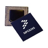
- Part No.:
- XPC8240LZU200E
- Manufacturer:
- NXP Semiconductors
- Category:
- Microprocessors
- Package:
- 352-LBGA
- Datasheet:
-
 XPC8240LZU200E.pdf
- Description:
- IC MPU MPC82XX 200MHZ 352TBGA
- Quantity:
- Payment:

- Shipping:

Inventory:2,518
Please send an inquiry. Send us your inquiry, and we will respond immediately.
Product details
Overview
XPC8240LZU200E from Freescale Semiconductor is a pilot-production prototype integrated processor combining PowerPC MPC603e core and PCI-to-PCI bridge logic in a single TBGA package. It operates at 200 MHz CPU frequency with 2.625 V ±5% core supply, supports 66 MHz PCI bus and 100 MHz memory bus, and targets embedded control applications requiring deterministic real-time response and legacy PCI expansion.
For engineers reviewing the XPC8240LZU200E datasheet, XPC8240LZU200E pinout, XPC8240LZU200E application, or XPC8240LZU200E equivalent, key selection criteria include verified PLL configuration support for 200 MHz operation, thermal junction range of 0–105°C, TBGA-480 package compatibility, and power management modes (Doze/Nap/Sleep) with sub-watt idle consumption.
Technical Context
The XPC8240LZU200E implements dual-phase PLL architecture: one VCO for peripheral/memory bus clock generation (PCI-to-Mem multiplier), another for CPU clock derivation (Mem-to-CPU multiplier). PLL_CFG[0:4] pins configure both multipliers simultaneously, with HID1[0:4] register reflecting only the CPU-side ratio.
It integrates MPC603e core with 32 KB instruction + 32 KB data cache, PCI controller compliant with PCI Rev 2.2, and memory controller supporting SDRAM. Power domains are segregated: VDD/AVDD/AVDD2/LAVDD at 2.625 V, OVDD/GVDD at 3.3 V, LVDD at 5.0 V or 3.3 V, with strict voltage sequencing constraints during power-up/down.
Key Specifications
| Parameter | Value and Actual Design Meaning |
|---|---|
| CPU Frequency | 200 MHz - Fixed maximum operating frequency confirmed for XPC8240LZU200E variant per Table A and PLL configuration Ref. No. 10. |
| Core Supply Voltage | 2.625 V ±5% - Required VDD/AVDD/AVDD2/LAVDD rail; deviation beyond ±131.25 mV invalidates 200 MHz timing compliance. |
| Operating Temperature | 0 to 105°C junction - Validated thermal range for continuous operation; exceeds commercial grade, suitable for industrial enclosures. |
| PCI Bus Clock | 66 MHz - Supported input range per PLL configuration Ref. No. 10 (PCI_SYNC_IN = 33–66 MHz); enables full-bandwidth PCI 2.2 transfers. |
| Memory Bus Clock | 100 MHz - Derived from peripheral logic PLL; enables 100 MHz SDRAM interface with 1:1 or 2:1 CPU-to-memory ratio. |
| Power Consumption (Typical) | 3.2 W - Measured at 66/100/200 MHz (PCI/Mem/CPU) with cache-resident integer workload; excludes I/O supply power. |
| Low-Power Modes | Doze (2.2 W), Nap (900 mW), Sleep (500 mW) - Hardware-supported states reducing dynamic power without losing context; validated at 200 MHz max CPU frequency. |
Pinout & Package
Package: TBGA-480 (Thin Ball Grid Array, 27 mm × 27 mm, 0.8 mm pitch), lead-free (RoHS-compliant), marked "XPC8240RXX200E" per Table 19 nomenclature.
| Pin/Terminal | Circuit Role | Design Meaning |
|---|---|---|
| PLL_CFG[0:4] | Configuration Input | 5-bit strap defining both memory and CPU PLL multipliers; determines valid 200 MHz operating point (Ref. No. 10 in Table 18). |
| VDD / AVDD / AVDD2 / LAVDD | Core & PLL Power | Dedicated 2.625 V supplies; must be independently decoupled; AVDD2 powers peripheral logic PLL, LAVDD powers DLL. |
| OVDD / GVDD | I/O Power | 3.3 V ±0.3 V supplies for PCI and memory bus drivers; OVDD powers PCI interface, GVDD powers SDRAM buffers. |
| LVDD | PCI Reference | 5.0 V or 3.3 V reference for PCI signaling; input-tolerant up to 5.75 V or 3.6 V respectively; critical for PCI compliance. |
| PCI_SYNC_IN | PCI Clock Input | Accepts 33–66 MHz differential or single-ended clock; directly drives peripheral logic PLL; defines base timing for all derived clocks. |
| HID1[0:4] | Status Output | Read-only register indicating active Mem-to-CPU multiplier; not unique to PLL_CFG setting-multiple configurations yield same HID1 value. |
Key Features
| Feature | Design Value |
|---|---|
| Dual-PLL Clock Generation | Independent memory bus (PCI-to-Mem) and CPU (Mem-to-CPU) frequency synthesis enables flexible 66/100/200 MHz tri-clock domain operation. |
| Integrated PCI Bridge Logic | Full PCI Rev 2.2 controller with arbiter, address decoder, and DMA engine eliminates need for external bridge chip in compact designs. |
| Hardware Power Management | Three low-power states (Doze/Nap/Sleep) reduce total system power by >85% vs. active mode while preserving register and cache state. |
| Input-Tolerant PCI Interface | LVDD input-tolerant signals (PCI, EPIC control, OSC_IN) accept 3.3 V or 5 V logic levels without level shifters, simplifying mixed-voltage board design. |
| Thermal Validation | Characterized across 0–105°C junction temperature range with guaranteed timing margins, enabling deployment in uncooled industrial environments. |
Applications
| Industrial PLC Controller | Communications Gateway |
|---|---|
|
Use Scenario: Real-time motion control in factory automation systems with distributed I/O over PCI-based fieldbus cards. IC Role / Device Role / Timing Role: Central processing unit and PCI host bridge managing deterministic interrupt latency and synchronized I/O scanning. Use Value: 200 MHz CPU frequency with 100 MHz SDRAM interface ensures <10 µs task scheduling jitter; 0–105°C rating supports DIN-rail mounted enclosures. |
Use Scenario: Protocol translation between legacy PCI-based modems and modern Ethernet backhaul in telecom access nodes. IC Role / Device Role / Timing Role: Embedded host processor executing protocol stacks while bridging PCI peripherals to internal memory-mapped registers. Use Value: Integrated PCI controller eliminates external bridge, reducing BOM count; 66 MHz PCI bandwidth sustains 52 Mbps T1/E1 aggregate throughput. |
| Ruggedized Medical Imaging Subsystem | Military Data Acquisition Unit |
|
Use Scenario: Image preprocessing pipeline in portable ultrasound devices using PCI-connected FPGA co-processors. IC Role / Device Role / Timing Role: High-reliability host processor coordinating DMA transfers between SDRAM frame buffers and PCI-based hardware accelerators. Use Value: Doze/Nap power modes cut standby consumption to 900 mW, extending battery life; TBGA-480 package resists vibration-induced solder fatigue. |
Use Scenario: Sensor fusion platform in vehicle-mounted C4ISR systems with MIL-STD-1553 and CAN interfaces routed via PCI add-in cards. IC Role / Device Role / Timing Role: Mission-critical control processor executing secure boot and real-time OS with hardware-enforced memory protection. Use Value: 2.625 V core supply with tight ±5% tolerance ensures stable operation under wide-input DC-DC regulation; 105°C junction rating accommodates conduction-cooled chassis. |
Equivalent & Alternatives
The following parts are listed as comparable options for similar integrated processor applications.
| Alternative Part | Technical Difference | Application Difference | Selection Advice |
|---|---|---|---|
| MPC8245RZUP200B | Production-grade version (no "X" prefix); identical 200 MHz spec, but qualified for full production reliability with extended characterization data. | Approved for long-lifecycle military/aerospace programs where pilot-prototype status is unacceptable. | Select when full qualification, traceable lot history, and guaranteed lifetime availability are required over cost-sensitive prototyping. |
| XPC8240RZU250E | Same TBGA-480 package and pinout; rated for 250 MHz CPU frequency with modified 2.625 V ±125 mV VDD tolerance. | Suitable for performance-scaling paths where higher clock rates justify tighter voltage regulation and thermal margin. | Select when system-level timing margins allow 250 MHz operation and PCB layout already accommodates enhanced decoupling for ±125 mV VDD. |
Compared with XPC8240LZU200E, MPC8245RZUP200B offers production reliability and lifecycle assurance, while XPC8240RZU250E provides headroom for frequency scaling-both retain identical pinout and software compatibility but differ in qualification status and voltage tolerance.
Availability
XPC8240LZU200E is available at Aetrix Electronics and suitable for industrial PLC controllers, communications gateways, ruggedized medical imaging subsystems, and military data acquisition units requiring stable component supply during design validation and low-volume deployment phases.
Supply support for XPC8240LZU200E includes scheduled delivery planning, volume procurement assistance, BOM continuity management, traceable sourcing, and lifecycle availability coordination for OEM customers, industrial embedded developers, connected-device designers, and electronics production programs.
Manufacturer
Freescale Semiconductor (now part of NXP Semiconductors) was a fabless semiconductor company specializing in embedded processors, analog, and connectivity solutions for automotive, industrial, and networking markets.
The MPC8240 product line delivers integrated PowerPC-based processors with embedded PCI bridge functionality, targeting space-constrained embedded systems needing high determinism, legacy bus support, and industrial temperature operation.
FAQ
What does the "X" prefix in XPC8240LZU200E signify?
The "X" prefix in XPC8240LZU200E indicates a pilot production prototype per Freescale SOP 3-13. These parts undergo qualified manufacturing and QA inspection but carry only preliminary reliability and characterization data. Customers must provide written authorization acknowledging the prototype status and potential for future product changes before shipment. XPC8240LZU200E remains fully functional for design validation and low-volume integration.
Is XPC8240LZU200E pin-compatible with other MPC8240 variants?
Yes, XPC8240LZU200E uses the TBGA-480 package and shares identical pinout with all RZU-suffixed MPC8240 parts, including XPC8240RZU250E and MPC8245RZUP200B. The "ZU" designation confirms TBGA packaging, and Freescale's part numbering nomenclature (Table 19) guarantees mechanical and electrical pin compatibility across this family. Signal assignments and power domain connections remain consistent.
What PLL configuration supports 200 MHz operation for XPC8240LZU200E?
XPC8240LZU200E achieves 200 MHz CPU frequency using PLL configuration Ref. No. 10 from Table 18: PLL_CFG[0:4] = 10000, PCI_SYNC_IN = 33–66 MHz, memory bus = 75–100 MHz, CPU clock = 150–200 MHz, with PCI-to-Mem multiplier = 3 and Mem-to-CPU multiplier = 2. This configuration is explicitly validated for the 200 MHz variant and requires correct strapping of PLL_CFG pins during power-on reset.
Does XPC8240LZU200E support 5 V-tolerant PCI signaling?
Yes, XPC8240LZU200E supports 5 V-tolerant PCI signaling on LVDD input-tolerant pins (PCI interface, EPIC control, OSC_IN), with absolute maximum input voltage of 5.75 V when LVDD is connected to 5.0 V. This allows direct interfacing with standard 5 V PCI slots without level-shifting circuitry, maintaining full PCI Rev 2.2 compliance while simplifying board design.
What are the power supply sequencing requirements for XPC8240LZU200E?
XPC8240LZU200E requires strict voltage sequencing: VDD/AVDD/AVDD2/LAVDD (2.625 V) must stabilize before OVDD/GVDD (3.3 V), and LVDD (5.0 V or 3.3 V) must not exceed VDD by more than 5.4 V or OVDD by more than 3.6 V during power-up/down. Violating these limits-even briefly beyond the 20 ms allowance-risks latch-up or permanent damage. Sequencing controllers or discrete RC networks are recommended for robust startup.
XPC8240LZU200E Specifications
- Product attributes
- Attribute value
- Manufacturer:
- NXP Semiconductors
- Package/Case:
- 352-LBGA
- Series:
- MPC82xx
- Packaging:
- Tray
- Product Status:
- Obsolete
- Core Processor:
- PowerPC 603e
- Number of Cores/Bus Width:
- 1 Core, 32-Bit
- Speed:
- 200MHz
- Co-Processors/DSP:
- -
- RAM Controllers:
- DRAM, SDRAM
- Graphics Acceleration:
- No
- Display & Interface Controllers:
- -
- Ethernet:
- -
- SATA:
- -
- USB:
- -
- Voltage - I/O:
- 3.3V
- Operating Temperature:
- 0°C ~ 105°C (TA)
- Grade:
- -
- Qualification:
- -
- Security Features:
- -
- Mounting Type:
- Surface Mount
- Supplier Device Package:
- 352-TBGA (35x35)
- Additional Interfaces:
- I2C, I²O, PCI, UART
XPC8240LZU200E FAQ
1.How can I place an order for XPC8240LZU200E through Aetrix?
Please submit a Request for Quotation (RFQ) for XPC8240LZU200E on Aetrix. Our sales agent will provide a competitive quotation and guide you through the order confirmation once you accept the terms.
2.Are the price and stock information for XPC8240LZU200E reliable?
The price and inventory of XPC8240LZU200E are updated periodically and may fluctuate due to market conditions. Stock and pricing data are typically refreshed every 24 hours. Quotation validity for XPC8240LZU200E is usually 5 days.
3.What payment methods are accepted for XPC8240LZU200E?
We accept Wire Transfer, PayPal, Credit Card, Western Union, MoneyGram, and Escrow for XPC8240LZU200E transactions.
Note: Certain payment methods may incur a processing fee.
4.How is shipping managed for XPC8240LZU200E?
XPC8240LZU200E orders can be shipped via leading logistics carriers, including DHL, UPS, FedEx, TNT, or Registered Mail.
Once your XPC8240LZU200E order is processed, you will receive an email with the shipment details and tracking number.
Note: Tracking information may take up to 24 hours to appear. Express delivery typically takes 3–5 business days.
5.How can I obtain technical support or documentation for XPC8240LZU200E?
For technical support, including XPC8240LZU200E datasheets, pinout diagrams, or application guidance, please contact our engineering support team. They can provide detailed documentation and assistance for your XPC8240LZU200E requirements.
6.How does Aetrix verify that XPC8240LZU200E is sourced from the original manufacturer or authorized distributors?
All XPC8240LZU200E products on Aetrix are procured from qualified distributors and authorized channels. Our dedicated quality assurance team conducts strict verification, including traceability checks and, if necessary, third-party testing. This ensures that XPC8240LZU200E meets industry standards.
7.What is the process for return or replacement of XPC8240LZU200E?
All XPC8240LZU200E units undergo pre-shipment inspection (PSI). If there is an issue with XPC8240LZU200E, returns or replacements are accepted under the following conditions:
1.Quantity discrepancies, incorrect items, or visible external defects (such as breakage or corrosion), acknowledged by Aetrix.
2.The issue is reported within 90 days of delivery.
3.The XPC8240LZU200E part is unused and in its original packaging.
Return procedure for XPC8240LZU200E:
1.Submit a request within 90 days.
2.Obtain a Return Material Authorization (RMA) from Aetrix.
XPC8240LZU200E Tags

-
AT91SAM9260B-CU-999
Microchip Technology
-
AT91SAM9G25-CU
Microchip Technology

-
ATSAMA5D27C-CU
Microchip Technology
-
AT91SAM9X35-CU
Microchip Technology
-
AT91SAM9X25-CU
Microchip Technology

-
MCIMX6Y2CVM08AB
NXP Semiconductors
.JPG)
-
AM3352BZCZ100
Texas Instruments
-
AT91SAM9260B-CU
Microchip Technology

-
AT91SAM9260B-QU
Microchip Technology

-
ATSAMA5D31A-CU
Microchip Technology
-
AT91SAM9G20B-CU-999
Microchip Technology
-
MCIMX6Y2CVM05AB
NXP Semiconductors
Tech Hub

A practical engineering guide to 3.3V and 5V logic compatibility, input thresholds, resistor dividers, translator ICs, MOSFET level shifting, I2C pull-ups, timing limits and power-sequencing risks.

The 74HC595 uses push-pull logic outputs, while the TPIC6B595 uses 50 V open-drain DMOS sinks for higher-power loads. This guide compares timing, current limits, 3.3 V interfacing, load wiring, thermal…

The 74HC595 converts serial data into eight stable parallel outputs. This guide covers pin functions, shift and storage timing, OE and MR behavior, drive-current limits, cascading, voltage compatibilit…

A technical comparison of level-sensitive latches and edge-triggered flip-flops, covering timing windows, setup and hold limits, master–slave operation, time borrowing, race-through, HDL inference and…

A D latch stores one bit while Enable controls when data can pass. This reference covers gate-level operation, truth tables, transparency, setup and hold timing, LE versus OE, common ICs and practical …

An SR latch stores one bit through cross-coupled feedback. This engineering reference covers NOR and NAND implementations, truth tables, forbidden-state recovery, gated operation, switch debouncing, fa…

Latch circuits retain one bit through feedback. This technical reference covers SR and D latches, truth tables, transparency, timing limits, latch-versus-flip-flop behavior, applications and common log…

An engineering guide to LED driver operation, constant-current and constant-voltage outputs, linear and switching topologies, dimming, IC selection, calculations, replacement compatibility, and fault c…

Operational amplifier guide covering op amp basics, feedback, ideal vs real op amps, common configurations, buffer circuits, offset, bias current, gain-bandwidth, slew rate, rail-to-rail limits and sel…

Jumper cables guide covering safe connection order, red and black clamp placement, final ground connection, cable gauge, length, clamp quality, copper vs CCA cables, jump starter comparison and battery…


