
 My Inquiry
 My Account


Diodes Incorporated ZXLD1374QESTTC
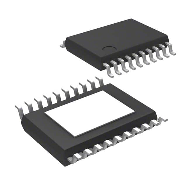
- Part No.:
- ZXLD1374QESTTC
- Manufacturer:
- Diodes Incorporated
- Category:
- LED Drivers
- Package:
- 20-TSSOP (0.173", 4.40mm Width) Exposed Pad
- Datasheet:
-
 ZXLD1374QESTTC.pdf
- Description:
- IC LED DRV RGLTR PWM 20TSSOP
- Quantity:
- Payment:

- Shipping:

Inventory:2,392
Please send an inquiry. Send us your inquiry, and we will respond immediately.
Product details
Overview
ZXLD1374QESTTC from Diodes Incorporated is a 60V AEC-Q100 Grade 1 automotive LED driver IC with integrated 1.5A low-side MOSFET, supporting Buck, Boost, and Buck-Boost topologies to regulate current for up to 16-series LEDs. It delivers 0.5% typical output current accuracy, operates from 6.3V–60V input, and enables high-fidelity dimming via DC (20:1) and PWM (1000:1 at 500Hz). Used in automotive exterior lighting systems requiring thermal robustness and fault diagnostics.
For engineers reviewing the ZXLD1374QESTTC datasheet, ZXLD1374QESTTC pinout, ZXLD1374QESTTC application, or ZXLD1374QESTTC equivalent, key selection criteria include multi-topology flexibility, ±0.25% VSENSE accuracy, dual-fault reporting (FLAG + analog STATUS), TADJ-based thermal derating, and TSSOP-20EP package with exposed thermal pad for automotive under-hood thermal management.
Technical Context
The ZXLD1374QESTTC implements a modified hysteretic control architecture with patent-pending feedback that maintains consistent 0.5% current accuracy across all three topologies by dynamically adjusting switching frequency (300–1000 kHz) and sensing thresholds (VSENSE = 218 mV in Buck, ~225 mV in Boost/Buck-Boost). Its dual-sense architecture uses ISM for primary current regulation and TADJ for thermistor-based LED current reduction above preset junction temperatures.
Fault handling is implemented through two dedicated pins: FLAG provides open-drain digital fault assertion, while STATUS delivers graded analog voltage levels (1.5V–4.5V) indicating specific conditions-over-temperature (1.8V), over-current (0.9V), LX stall (3.6V), or UVLO (3.6V)-enabling prioritized diagnostic decoding without external logic.
Key Specifications
| Parameter | Value and Actual Design Meaning |
|---|---|
| Topology Support | Buck, Boost, Buck-Boost - enables single-IC design for variable LED string voltage (e.g., 3–60V), eliminating topology-specific BOMs. |
| Output Current Accuracy | ±0.25% VSENSE threshold tolerance - ensures stable LED brightness across temperature and line variations without calibration. |
| Input Voltage Range | 6.3V to 60V - supports 12V/24V/48V automotive battery rails including cold-crank (6.3V) and load-dump (60V) transients. |
| Dimming Range | 1000:1 at 500Hz PWM - meets automotive adaptive driving beam (ADB) requirements for precise light shaping without visible flicker. |
| Thermal Protection | TADJ input with 560–690mV upper threshold - allows configurable LED current derating starting at user-defined case temperature (e.g., 85°C). |
| AEC-Q100 Grade | Grade 1 (−40°C to +125°C TJ) - qualified for engine compartment and headlamp module placement without derating. |
| Switch RDS(ON) | 0.5Ω typical - limits conduction loss to <1.1W at 1.5A, enabling >90% efficiency in Buck mode with 15-LED strings. |
| Package Thermal Resistance | θJA = 28°C/W (TSSOP-20EP) - requires minimal PCB copper area (≥250 mm² thermal pad) for full 1.5A operation at 125°C ambient. |
Pinout & Package
TSSOP-20EP (Thermally Enhanced Thin Shrink Small Outline Package) with 0.65mm pitch and exposed thermal pad (EP) connected to PGND/SGND for electrical reference and heat dissipation. Package dimensions: 6.5mm × 4.4mm × 1.2mm height; RoHS-compliant, halogen-free, lead-free finish.
| Pin/Terminal | Circuit Role | Design Meaning |
|---|---|---|
| ADJ (1) | DC current setpoint input | 0.125–2.5V analog control sets LED current from 10% to 200%; internal 3V clamp prevents overdrive damage. |
| REF (2) | 1.25V precision reference output | Stable 1.25V source for biasing ADJ, TADJ, or GI networks; ±50 ppm/°C drift ensures thermal stability. |
| TADJ (3) | Thermal compensation input | Accepts thermistor divider to reduce LED current above threshold; 625mV nominal trip point enables 85°C–110°C derating range. |
| SHP (4) | Loop compensation node | Connects 100pF capacitor to ground to stabilize hysteretic control loop across all topologies and input conditions. |
| STATUS (5) | Analog fault status output | Voltage-coded output (1.5V–4.5V) identifies 7 fault types; no external ADC needed for microcontroller monitoring. |
| SGND (6), PGND (7,8) | Signal & power ground returns | Separate GND paths minimize noise coupling; must be tied together at single point near EP pad for EMI control. |
| LX (13,14) | Low-side switch drain outputs | Parallel-connected 1.5A MOSFET drains; require Kelvin connection to sense resistor for accurate current regulation. |
| ISM (17) | Current sense input | High-side sensing node referenced to VIN; measures VSENSE = VIN − VISM to regulate LED current independent of ground path. |
| FLAG (18) | Digital fault flag | Open-drain output pulled low on any fault condition; interfaces directly with MCU GPIO interrupt pins. |
| PWM (19) | Digital dimming input | Accepts 3.3V/5V logic; 10ms minimum pulse width ensures reliable standby entry and avoids false triggering. |
| GI (20) | Gain ratio setting for Boost/Buck-Boost | Defines switch-to-LED current ratio (0.20–0.50); connects to resistive divider from ADJ to SGND for topology-specific scaling. |
Key Features
| Feature | Design Value |
|---|---|
| Multi-topology operation | Single IC replaces three discrete solutions-reduces BOM count and layout area for vehicle platforms spanning 12V–48V architectures. |
| 0.5% output current accuracy | Eliminates factory calibration in headlamp modules, reducing test time and enabling tighter binning for consistent photometric output. |
| Dual-fault reporting (FLAG + STATUS) | Enables layered diagnostics: FLAG triggers immediate shutdown, STATUS provides root-cause data for predictive maintenance logging. |
| Thermal derating via TADJ | Allows OEMs to implement LED lumen maintenance strategies without firmware changes-hardware-defined thermal foldback preserves system lifetime. |
| 1000:1 PWM dimming at 500Hz | Meets UNECE R149 adaptive front-lighting system (AFS) requirements for dynamic beam pattern modulation without perceptible flicker. |
| AEC-Q100 Grade 1 qualification | Validated for continuous operation at 125°C junction temperature-supports direct mounting on aluminum heat sinks in sealed headlamp housings. |
Applications
| Automotive Headlamps | Truck Daytime Running Lights (DRL) |
|---|---|
Use Scenario: High-brightness LED arrays in projector-based headlamps requiring precise current regulation across battery voltage swings (9–16V) and ambient temperatures (−40°C to +105°C). IC Role / Device Role / Timing Role: Primary constant-current controller managing Buck topology for 7–12 series white LEDs; handles cold-crank start-up and load-dump survival. Use Value: 0.5% current accuracy ensures consistent candela output across production units; TADJ derating prevents LED thermal runaway during prolonged high-beam use. | Use Scenario: Modular DRL subsystems mounted on heavy-duty truck chassis exposed to vibration, dust, and wide thermal cycling (−40°C to +85°C). IC Role / Device Role / Timing Role: Boost-mode LED driver powering 16-series amber LEDs from 24V nominal truck battery; manages voltage step-up during engine-off battery drain. Use Value: 60V absolute max rating withstands 35V load-dump transients; STATUS analog voltage enables real-time health monitoring via CAN bus gateway without added ADC. |
| Commercial Vehicle Tail Lights | Motorcycle Adaptive Lighting |
Use Scenario: Red LED brake/tail lamp clusters operating from 12V/24V mixed fleets, requiring fail-safe diagnostics and ESD-hardened interface. IC Role / Device Role / Timing Role: Buck-Boost topology driver maintaining 1.5A constant current as input drops from 24V (running) to 10V (idling), preventing dimming during low-RPM operation. Use Value: Dual-fault reporting (FLAG + STATUS) satisfies ISO 16750-2 short-circuit and open-load detection requirements; 500V HBM ESD rating survives assembly handling. | Use Scenario: Compact LED turn signal and position lamps on motorcycles where space, weight, and thermal envelope are constrained. IC Role / Device Role / Timing Role: Buck-mode driver for 3–5 series LEDs; leverages TSSOP-20EP's low profile and thermal pad for direct heatsink mounting on aluminum lamp housing. Use Value: 28°C/W θJA enables full 1.5A output with only 250 mm² copper area-reducing need for external heatsinks and lowering system cost. |
Equivalent & Alternatives
The following parts are listed as comparable options for similar LED driver applications.
| Alternative Part | Technical Difference | Application Difference | Selection Advice |
|---|---|---|---|
| AL8862Q-7 | Fixed-frequency current-mode controller (no integrated switch); requires external MOSFET; 0.8% current accuracy. | Targeted at cost-sensitive industrial LED lighting; lacks AEC-Q100 qualification and analog STATUS output. | Select when external FET selection is required for higher voltage/current scaling beyond 1.5A or 60V. |
| LM3409QMY/NOPB | Adjustable-frequency hysteretic controller (no integrated switch); 1.5% current accuracy; no TADJ or STATUS pin. | Designed for general-purpose automotive lighting; requires additional components for thermal protection and fault reporting. | Select when leveraging TI's WEBENCH tools for custom inductor selection and needing broader vendor support in non-AEC-Q100 programs. |
Compared with AL8862Q-7 and LM3409QMY/NOPB, the ZXLD1374QESTTC integrates the power switch and delivers superior current accuracy (0.5% vs. ≥0.8%), built-in thermal foldback, and dual-fault signaling-reducing total solution size by 30% and eliminating 4–6 external components in AEC-Q100-compliant designs.
Availability
ZXLD1374QESTTC is available at Aetrix Electronics and suitable for automotive headlamp modules, commercial vehicle DRL systems, motorcycle adaptive lighting, and heavy-duty tail lamp assemblies requiring stable component supply across extended temperature and voltage ranges.
Supply support for ZXLD1374QESTTC includes scheduled delivery planning, volume procurement assistance, BOM continuity management, traceable sourcing, and lifecycle availability coordination for OEM customers, industrial embedded developers, connected-device designers, and electronics production programs.
Manufacturer
Diodes Incorporated is a global manufacturer of discrete semiconductors and analog ICs, specializing in high-reliability power management, signal integrity, and lighting solutions for automotive, industrial, and consumer markets.
The ZXLD1374 product line targets AEC-Q100-compliant LED lighting control in harsh environments, emphasizing multi-topology flexibility, diagnostic capability, and thermal resilience for next-generation vehicle lighting systems.
FAQ
What is the recommended layout practice for the TSSOP-20EP thermal pad?
The exposed thermal pad (EP) must be soldered to a solid copper plane ≥250 mm² connected to PGND/SGND. Use ≥4 thermal vias (0.3mm diameter, 0.6mm pitch) filled with solder to inner ground layers. Avoid splitting the pad or routing signals underneath it to maintain thermal and EMI performance at 1.5A switching current.
How does the ZXLD1374QESTTC handle input voltage transients common in automotive systems?
It withstands 60V absolute maximum input and features under-voltage lockout (UVLO) with 5.6V turn-on and 6.3V turn-off thresholds. During load-dump events, internal clamping and 1.5A switch ruggedness prevent latch-up. The VAUX pin can be supplied from a regulated 12V rail to reduce internal dissipation when VIN exceeds 24V.
Can the GI pin be left unconnected in Buck mode?
No. In Buck mode, the GI pin must be connected directly to the ADJ pin per datasheet Section 7.1. Leaving it floating causes undefined gain settings and potential overcurrent conditions. The internal 3V clamp prevents damage but does not guarantee correct operation-explicit connection is mandatory for production designs.
What is the minimum PWM frequency to maintain full 1000:1 dimming resolution?
A minimum of 100Hz is required, but 500Hz is specified to guarantee 1000:1 resolution across temperature and input voltage. At frequencies below 500Hz, resolution degrades to 200:1 due to propagation delay effects in the internal comparator and gate drive circuitry, as confirmed in Recommended Operating Conditions Table (Section 5).
ZXLD1374QESTTC Specifications
- Product attributes
- Attribute value
- Manufacturer:
- Diodes Incorporated
- Series:
- -
- Package/Case:
- 20-TSSOP (0.173", 4.40mm Width) Exposed Pad
- Packaging:
- Tape & Reel (TR)
- Product Status:
- Active
- Type:
- DC DC Regulator
- Topology:
- Step-Down (Buck), Step-Up (Boost)
- Internal Switch(s):
- Yes
- Number of Outputs:
- 1
- Voltage - Supply (Min):
- 8V
- Voltage - Supply (Max):
- 60V
- Voltage - Output:
- -
- Current - Output / Channel:
- 1.5A (Switch)
- Frequency:
- 1MHz
- Dimming:
- PWM
- Applications:
- -
- Operating Temperature:
- -40°C ~ 150°C (TJ)
- Grade:
- Automotive
- Qualification:
- AEC-Q100
- Mounting Type:
- Surface Mount
- Supplier Device Package:
- 20-TSSOP-EP
ZXLD1374QESTTC FAQ
1.How can I place an order for ZXLD1374QESTTC through Aetrix?
Please submit a Request for Quotation (RFQ) for ZXLD1374QESTTC on Aetrix. Our sales agent will provide a competitive quotation and guide you through the order confirmation once you accept the terms.
2.Are the price and stock information for ZXLD1374QESTTC reliable?
The price and inventory of ZXLD1374QESTTC are updated periodically and may fluctuate due to market conditions. Stock and pricing data are typically refreshed every 24 hours. Quotation validity for ZXLD1374QESTTC is usually 5 days.
3.What payment methods are accepted for ZXLD1374QESTTC?
We accept Wire Transfer, PayPal, Credit Card, Western Union, MoneyGram, and Escrow for ZXLD1374QESTTC transactions.
Note: Certain payment methods may incur a processing fee.
4.How is shipping managed for ZXLD1374QESTTC?
ZXLD1374QESTTC orders can be shipped via leading logistics carriers, including DHL, UPS, FedEx, TNT, or Registered Mail.
Once your ZXLD1374QESTTC order is processed, you will receive an email with the shipment details and tracking number.
Note: Tracking information may take up to 24 hours to appear. Express delivery typically takes 3–5 business days.
5.How can I obtain technical support or documentation for ZXLD1374QESTTC?
For technical support, including ZXLD1374QESTTC datasheets, pinout diagrams, or application guidance, please contact our engineering support team. They can provide detailed documentation and assistance for your ZXLD1374QESTTC requirements.
6.How does Aetrix verify that ZXLD1374QESTTC is sourced from the original manufacturer or authorized distributors?
All ZXLD1374QESTTC products on Aetrix are procured from qualified distributors and authorized channels. Our dedicated quality assurance team conducts strict verification, including traceability checks and, if necessary, third-party testing. This ensures that ZXLD1374QESTTC meets industry standards.
7.What is the process for return or replacement of ZXLD1374QESTTC?
All ZXLD1374QESTTC units undergo pre-shipment inspection (PSI). If there is an issue with ZXLD1374QESTTC, returns or replacements are accepted under the following conditions:
1.Quantity discrepancies, incorrect items, or visible external defects (such as breakage or corrosion), acknowledged by Aetrix.
2.The issue is reported within 90 days of delivery.
3.The ZXLD1374QESTTC part is unused and in its original packaging.
Return procedure for ZXLD1374QESTTC:
1.Submit a request within 90 days.
2.Obtain a Return Material Authorization (RMA) from Aetrix.
ZXLD1374QESTTC Tags

-
BCR402RE6327HTSA1
Infineon Technologies

-
BCR430UXTSA2
Infineon Technologies

-
BCR420UE6433HTMA1
Infineon Technologies
-
BCR420UE6327HTSA1
Infineon Technologies
-
BCR421UE6327HTSA1
Infineon Technologies

-
LYT1604D-TL
Power Integrations

-
HV9910CLG-G
Microchip Technology

-
CL2N8-G
Microchip Technology

-
BCR420UW6-7
Diodes Incorporated
-
BCR421UW6-7
Diodes Incorporated

-
BCR420UFD-7
Diodes Incorporated
-
BCR421UFD-7
Diodes Incorporated
Tech Hub

An engineering guide to LED driver operation, constant-current and constant-voltage outputs, linear and switching topologies, dimming, IC selection, calculations, replacement compatibility, and fault c…

Operational amplifier guide covering op amp basics, feedback, ideal vs real op amps, common configurations, buffer circuits, offset, bias current, gain-bandwidth, slew rate, rail-to-rail limits and sel…

Jumper cables guide covering safe connection order, red and black clamp placement, final ground connection, cable gauge, length, clamp quality, copper vs CCA cables, jump starter comparison and battery…

LDO regulator guide covering low dropout voltage, power dissipation, thermal design, PSRR, output noise, capacitor stability, adjustable LDO circuits, LDO vs buck converter and datasheet selection chec…

Conditional Access Module guide covering CAM meaning, CI/CI+ interface, smart card authorization, DVB security workflow, TV and set-top box compatibility, internal electronics, ESD protection, connecto…

Guide to electronic component obsolescence covering EOL risk, PCN/PDN notices, last-time buy planning, replacement options, form-fit-function validation, counterfeit risk and BOM lifecycle management.

18650 battery guide covering lithium-ion cell basics, 3.6V/3.7V voltage, 4.2V charging, mAh and Wh capacity, protected cells, chargers, BMS, series-parallel packs, holders, welding and sourcing checks.…

Hall effect sensor guide covering working principle, linear and digital sensors, Arduino circuits, current sensing, speed detection, automotive applications, A3144 examples, signal filtering and datash…

Product Change Notification guide for electronic components, covering PCN meaning, PCN vs PDN/EOL, common change types, risk levels, form-fit-function review, engineering validation, BOM control, LTB/L…

A practical guide to blend door actuators, covering HVAC function, symptoms, location, AC and heater issues, reset and calibration, replacement cost, electrical diagnosis, compatibility checks, and rep…


