
 My Inquiry
 My Account


Diodes Incorporated ZXMS6004DN8-13
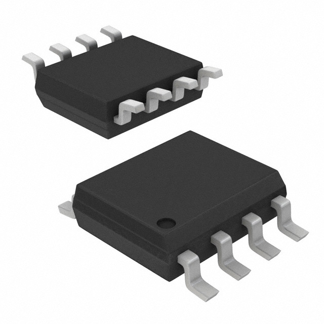
- Part No.:
- ZXMS6004DN8-13
- Manufacturer:
- Diodes Incorporated
- Package:
- 8-SOIC (0.154", 3.90mm Width)
- Datasheet:
-
 ZXMS6004DN8-13.pdf
- Description:
- IC PWR DRIVER N-CHANNEL 1:1 8SO
- Quantity:
- Payment:

- Shipping:

Inventory:38,563
Please send an inquiry. Send us your inquiry, and we will respond immediately.
Product details
Overview
ZXMS6004DN8-13 from Diodes Incorporated is a dual-channel, 60V N-channel self-protected low-side IntelliFET® MOSFET with logic-level input (3.3V/5V compatible), 400–600 mΩ RDS(ON), 1.3A nominal load current at 5V, and integrated overvoltage (active clamp), overcurrent, thermal shutdown, and ESD protection. It serves as a rugged, drop-in replacement for electromechanical relays and discrete switch circuits in harsh industrial loads.
For engineers reviewing the ZXMS6004DN8-13 datasheet, ZXMS6004DN8-13 pinout, ZXMS6004DN8-13 application, or ZXMS6004DN8-13 equivalent, this device is selected for high-reliability DC switching of inductive/resistive loads where fault resilience, μC compatibility, and SO-8 board-mount integration are critical - especially in lamp, motor, solenoid, and relay driver designs.
Technical Context
The ZXMS6004DN8-13 integrates two electrically isolated low-side power switches in a single SO-8 package, each featuring active VDS clamping (60–70 V), current limiting (1.7 A typ. at 5 V), and thermal trip at +150 °C with +10 °C hysteresis. Its logic-level gate drive enables direct interfacing with 3.3 V and 5 V microcontrollers without level-shifting circuitry.
It operates across –40 °C to +125 °C ambient, supports linear-mode operation with inherent current-limit deactivation at low VDS, and delivers 120 mJ unclamped inductive energy rating. Protection functions auto-restart after fault clearance, ensuring robust recovery in transient overload conditions.
Key Specifications
| Parameter | Value and Actual Design Meaning |
|---|---|
| VDS (max) | 60 V - Supports 24 V DC systems with 150 % voltage margin against transients |
| RDS(ON) | 400–600 mΩ @ 5 V - Enables ≤1.3 A continuous load current with <1 W conduction loss at 1 A |
| ID(LIM) | 1.7 A typ. @ 5 V - Limits peak fault current during short-circuit events to protect downstream wiring |
| EAS | 120 mJ - Withstands inductive kickback from lamps/motors without external snubbers |
| VIN(th) | 0.7–1.5 V - Ensures reliable turn-on with standard 3.3 V GPIOs even under voltage droop |
| TJ(max) | +150 °C - Allows operation in sealed enclosures or high-ambient industrial environments |
| PD @ 25°C | 1.21 W (FR-4, min pad) - Defines thermal design baseline for PCB copper area requirements |
Pinout & Package
Package: SO-8, surface-mount, lead-free, RoHS-compliant, UL 94V-0 molded plastic housing weighing 79.1 mg. Thermal resistance junction-to-ambient is 103 °C/W (min pad) or 81 °C/W (1-inch copper plate).
| Pin/Terminal | Circuit Role | Design Meaning |
|---|---|---|
| IN1 | Channel 1 gate input | Logic-level control signal (0–5.5 V); accepts direct MCU GPIO drive |
| S1 | Channel 1 source | Low-side return path; tied to system ground or shared common |
| D1 | Channel 1 drain | Switched load connection; carries full load current and clamps at 60–70 V |
| IN2 | Channel 2 gate input | Independent logic-level control; electrically isolated from IN1 |
| S2 | Channel 2 source | Second low-side return; may be tied separately or paralleled per design |
| D2 | Channel 2 drain | Second switched load node; fully independent with identical protection |
| NC | No connect | Pin 7 is internally unused; must remain unconnected per datasheet |
| NC | No connect | Pin 8 is internally unused; no routing or soldering required |
Key Features
| Feature | Design Value |
|---|---|
| Short-circuit protection with auto-restart | Clamps VDS and limits ID during sustained overload, then recovers automatically when fault clears |
| Active overvoltage clamp | Internal Zener-like clamp activates at 60–70 V to suppress inductive spikes without external components |
| Thermal shutdown with hysteresis | Shuts off at +150 °C and re-enables only after cooling by ≥10 °C, preventing thermal cycling instability |
| ESD-hardened inputs | HBM rating of 4 kV and CDM rating of 1 kV ensure robustness against handling and board-level ESD events |
| Logic-level compatibility | Operates fully with 3.3 V and 5 V microcontroller outputs - no external gate driver needed |
Applications
| Lamp Driver | Motor Driver |
|---|---|
|
Use Scenario: Switching incandescent or LED lighting loads in automotive cabins or industrial control panels with high inrush current. IC Role / Device Role: Low-side power switch with active current limiting and thermal foldback to prevent filament surge damage. Use Value: Eliminates need for external current-sense resistors and thermal fuses while sustaining 1.3 A steady-state and >2 A pulsed loads. |
Use Scenario: Driving brushed DC motors in HVAC actuators or valve positioners requiring bidirectional control via H-bridge complement. IC Role / Device Role: Single-channel half-bridge low-side switch enabling PWM speed control and stall protection. Use Value: Withstands 120 mJ inductive energy and auto-recovers from stall faults - reducing firmware watchdog complexity. |
| Relay Replacement | Solenoid Driver |
|
Use Scenario: Replacing electromechanical relays in PLC output modules where contact wear, bounce, and coil drive limitations exist. IC Role / Device Role: Solid-state, zero-crossing–free switching element with integrated flyback energy absorption. Use Value: Delivers >100 k-cycle reliability, silent operation, and 5× faster switching than 12 V relays - with no external diode required. |
Use Scenario: Energizing industrial solenoids in fluid control systems subject to voltage transients and ambient temperatures up to +125 °C. IC Role / Device Role: Protected low-side driver with active VDS clamping and thermal derating down to –40 °C. Use Value: Maintains 1.0 A continuous drive capability across full temperature range while surviving 36 V clamp-rated transients. |
Equivalent & Alternatives
The following parts are listed as comparable options for similar protected low-side switching applications.
| Alternative Part | Technical Difference | Application Difference | Selection Advice |
|---|---|---|---|
| Infineon BTS716G | Single-channel, higher RDS(ON) (800 mΩ), lower VDS (40 V), no active clamp | Limited to 24 V systems; requires external TVS for inductive loads | Select for cost-sensitive single-load applications where 40 V rating suffices and external protection is acceptable |
| STMicroelectronics VND5E025AK | Dual-channel, 40 V rating, 25 mΩ RDS(ON), integrated diagnostics (current sense, fault flag) | Requires SPI interface for status readback; not logic-level direct-drive | Select when diagnostic feedback and ultra-low on-resistance are prioritized over simplicity and 60 V headroom |
Compared with BTS716G and VND5E025AK, the ZXMS6004DN8-13 uniquely balances 60 V ruggedness, dual-channel logic-level operation, and self-contained active clamping - making it optimal for compact, high-transient industrial switch nodes without added protection components or interface overhead.
Availability
ZXMS6004DN8-13 is available at Aetrix Electronics and suitable for lamp drivers, motor controllers, relay replacements, and solenoid actuation requiring stable component supply, long-term lifecycle assurance, and compliance with RoHS and halogen-free standards.
Supply support for ZXMS6004DN8-13 includes scheduled delivery planning, volume procurement assistance, BOM continuity management, traceable sourcing, and lifecycle availability coordination for OEM customers, industrial embedded developers, connected-device designers, and electronics production programs.
Manufacturer
Diodes Incorporated is a global manufacturer of discrete semiconductors and analog ICs, specializing in high-reliability power management, signal integrity, and protection solutions for industrial, automotive, and computing markets.
The ZXMS6004DN8-13 belongs to Diodes' IntelliFET® family - engineered specifically for ruggedized, self-protected low-side switching in harsh environments where discrete MOSFETs and mechanical relays fail prematurely.
FAQ
Can ZXMS6004DN8-13 drive inductive loads without external flyback diodes?
Yes. The device integrates active overvoltage clamping that limits VDS to 60–70 V during inductive turn-off, eliminating the need for external freewheeling diodes in most 24 V DC applications. This is confirmed by its 120 mJ EAS rating and functional block diagram showing internal clamp circuitry.
What is the maximum continuous current per channel at +85 °C ambient?
At +85 °C ambient, the continuous current is thermally limited to approximately 0.75 A per channel when mounted on a standard FR-4 board with minimum recommended copper pads (RθJA = 103 °C/W). Derating curves in Figure 1 of DS38040 confirm this value based on 1.21 W PD and 150 °C TJ(max).
Does ZXMS6004DN8-13 support PWM dimming of LED loads?
Yes. Its fast switching times (tr = 10 µs, tf = 15 µs) and logic-level compatibility enable clean 1–20 kHz PWM dimming without shoot-through or thermal runaway. The current-limit function remains active during PWM, protecting against LED string short-circuits.
Is the SO-8 package pinout compatible with industry-standard dual MOSFET footprints?
Yes. The ZXMS6004DN8-13 uses a standard SO-8 outline (per AP02002) with 1.27 mm pitch, matching JEDEC MS-012. Pin 1 (IN1) is marked by a notch or dot; pins 7 and 8 are NC and must remain unconnected - consistent with common dual-FET layout practices.
ZXMS6004DN8-13 Specifications
- Product attributes
- Attribute value
- Manufacturer:
- Diodes Incorporated
- Package/Case:
- 8-SOIC (0.154", 3.90mm Width)
- Series:
- INTELLIFET®
- Packaging:
- Tape & Reel (TR)
- Product Status:
- Active
- Switch Type:
- General Purpose
- Number of Outputs:
- 2
- Ratio - Input:Output:
- 1:1
- Output Configuration:
- Low Side
- Output Type:
- N-Channel
- Interface:
- On/Off
- Voltage - Load:
- 60V (Max)
- Voltage - Supply (Vcc/Vdd):
- 3.3V, 5V
- Current - Output (Max):
- 1.3A
- Rds On (Typ):
- 350mOhm
- Input Type:
- Non-Inverting
- Features:
- Auto Restart
- Fault Protection:
- Current Limiting (Fixed), Over Temperature, Over Voltage
- Operating Temperature:
- -40°C ~ 125°C (TA)
- Grade:
- -
- Qualification:
- -
- Mounting Type:
- Surface Mount
- Supplier Device Package:
- 8-SO
ZXMS6004DN8-13 FAQ
1.How can I place an order for ZXMS6004DN8-13 through Aetrix?
Please submit a Request for Quotation (RFQ) for ZXMS6004DN8-13 on Aetrix. Our sales agent will provide a competitive quotation and guide you through the order confirmation once you accept the terms.
2.Are the price and stock information for ZXMS6004DN8-13 reliable?
The price and inventory of ZXMS6004DN8-13 are updated periodically and may fluctuate due to market conditions. Stock and pricing data are typically refreshed every 24 hours. Quotation validity for ZXMS6004DN8-13 is usually 5 days.
3.What payment methods are accepted for ZXMS6004DN8-13?
We accept Wire Transfer, PayPal, Credit Card, Western Union, MoneyGram, and Escrow for ZXMS6004DN8-13 transactions.
Note: Certain payment methods may incur a processing fee.
4.How is shipping managed for ZXMS6004DN8-13?
ZXMS6004DN8-13 orders can be shipped via leading logistics carriers, including DHL, UPS, FedEx, TNT, or Registered Mail.
Once your ZXMS6004DN8-13 order is processed, you will receive an email with the shipment details and tracking number.
Note: Tracking information may take up to 24 hours to appear. Express delivery typically takes 3–5 business days.
5.How can I obtain technical support or documentation for ZXMS6004DN8-13?
For technical support, including ZXMS6004DN8-13 datasheets, pinout diagrams, or application guidance, please contact our engineering support team. They can provide detailed documentation and assistance for your ZXMS6004DN8-13 requirements.
6.How does Aetrix verify that ZXMS6004DN8-13 is sourced from the original manufacturer or authorized distributors?
All ZXMS6004DN8-13 products on Aetrix are procured from qualified distributors and authorized channels. Our dedicated quality assurance team conducts strict verification, including traceability checks and, if necessary, third-party testing. This ensures that ZXMS6004DN8-13 meets industry standards.
7.What is the process for return or replacement of ZXMS6004DN8-13?
All ZXMS6004DN8-13 units undergo pre-shipment inspection (PSI). If there is an issue with ZXMS6004DN8-13, returns or replacements are accepted under the following conditions:
1.Quantity discrepancies, incorrect items, or visible external defects (such as breakage or corrosion), acknowledged by Aetrix.
2.The issue is reported within 90 days of delivery.
3.The ZXMS6004DN8-13 part is unused and in its original packaging.
Return procedure for ZXMS6004DN8-13:
1.Submit a request within 90 days.
2.Obtain a Return Material Authorization (RMA) from Aetrix.
ZXMS6004DN8-13 Tags

-
TPS22919DCKR
Texas Instruments

-
MIC2091-1YM5-TR
Microchip Technology

-
MIC2090-1YM5-TR
Microchip Technology

-
TPS22995RZFR
Texas Instruments

-
TPS22975DSGR
Texas Instruments

-
SIP32510DT-T1-GE3
Vishay Siliconix

-
ULN2003D1013TR
STMicroelectronics

-
MIC2005A-1YM5-TR
Microchip Technology

-
MIC2005A-1YM6-TR
Microchip Technology

-
TPS22916BYFPR
Texas Instruments

-
TPS22917DBVR
Texas Instruments

-
ULN2003APWR
Texas Instruments
Tech Hub

Operational amplifier guide covering op amp basics, feedback, ideal vs real op amps, common configurations, buffer circuits, offset, bias current, gain-bandwidth, slew rate, rail-to-rail limits and sel…

Jumper cables guide covering safe connection order, red and black clamp placement, final ground connection, cable gauge, length, clamp quality, copper vs CCA cables, jump starter comparison and battery…

LDO regulator guide covering low dropout voltage, power dissipation, thermal design, PSRR, output noise, capacitor stability, adjustable LDO circuits, LDO vs buck converter and datasheet selection chec…

Conditional Access Module guide covering CAM meaning, CI/CI+ interface, smart card authorization, DVB security workflow, TV and set-top box compatibility, internal electronics, ESD protection, connecto…

Guide to electronic component obsolescence covering EOL risk, PCN/PDN notices, last-time buy planning, replacement options, form-fit-function validation, counterfeit risk and BOM lifecycle management.

18650 battery guide covering lithium-ion cell basics, 3.6V/3.7V voltage, 4.2V charging, mAh and Wh capacity, protected cells, chargers, BMS, series-parallel packs, holders, welding and sourcing checks.…

Hall effect sensor guide covering working principle, linear and digital sensors, Arduino circuits, current sensing, speed detection, automotive applications, A3144 examples, signal filtering and datash…

Product Change Notification guide for electronic components, covering PCN meaning, PCN vs PDN/EOL, common change types, risk levels, form-fit-function review, engineering validation, BOM control, LTB/L…

A practical guide to blend door actuators, covering HVAC function, symptoms, location, AC and heater issues, reset and calibration, replacement cost, electrical diagnosis, compatibility checks, and rep…

Engineering guide to Raspberry Pi alternatives, covering chip-level differences, Orange Pi, ROCK, Jetson, Banana Pi, NanoPi, Compute Module, Pico, GPIO, camera, HAT compatibility, and replacement risks…


