Send an Inquiry

To receive a quote for your project, please fill in the following information, and we’ll get back to you promptly.

Name*
Company*
Email Address*
Phone/WhatsApp
Part Number*
Quantity*
Message
Submit Inventory List

Please fill in the following information, and we’ll get back to you promptly.

Name*
Company*
Email Address*
Phone/WhatsApp
Upload My List
Message

Vishay General Semiconductor - Diodes Division 1.5KE24CAHE3/51
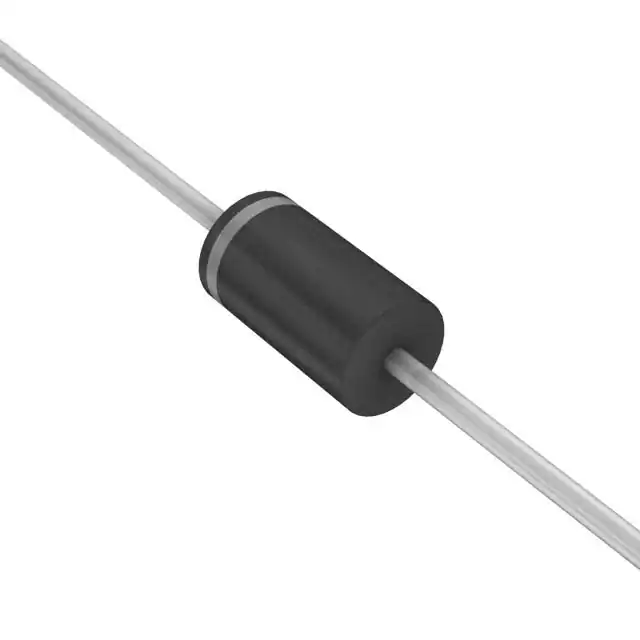
Part No.:
1.5KE24CAHE3/51
Manufacturer:
Vishay General Semiconductor - Diodes Division
Category:
TVS Diodes
Package:
DO-201AA, DO-27, Axial
Datasheet:
Aetrix1.5KE24CAHE3/51.pdf
Description:
TVS DIODE 20.5VWM 33.2VC 1.5KE
Quantity:
Payment:
Payment
Shipping:
Shipping

Inventory:5,802

Please send an inquiry. Send us your inquiry, and we will respond immediately.

Part Number
Quantity*
Price
Name*
Company
Email*
Comments

Product details

Overview

1.5KE24CAHE3/51 from Vishay General Semiconductor is a bi-directional Transient Voltage Suppressor (TVS) diode designed for robust overvoltage protection in power and signal lines. It features a 24 V breakdown voltage (VBR = 22.8–25.2 V at IT = 1.0 mA), 1500 W peak pulse power (10/1000 µs), clamping voltage of 33.2 V at 45.2 A, and operates across –55 °C to +175 °C junction temperature range - deployed in automotive sensor interfaces and industrial I/O protection.

For engineers reviewing the 1.5KE24CAHE3/51 datasheet, 1.5KE24CAHE3/51 pinout, 1.5KE24CAHE3/51 application, or 1.5KE24CAHE3/51 equivalent, this page delivers verified electrical specs, AEC-Q101 qualification status, clamping performance under surge conditions, thermal resistance (RθJL = 15.4 °C/W), and RoHS-compliant HE3 packaging details - all critical for ESD/lightning transient design validation.

Technical Context

This bi-directional TVS diode uses a glass passivated silicon junction to achieve sub-nanosecond response time (<1 ns) and low incremental surge resistance, enabling effective clamping of fast transients induced by inductive switching or lightning surges. Its symmetrical bidirectional structure eliminates polarity concerns in AC-coupled or floating lines.

The device complies with AEC-Q101 for automotive applications and supports repetitive 10/1000 µs surge pulses at 0.01% duty cycle. With VWM = 20.5 V and IR ≤ 1.0 µA at rated standoff, it ensures minimal leakage during normal operation while maintaining tight VBR tolerance (±5%).

Key Specifications

Parameter Value and Actual Design Meaning
Breakdown Voltage VBR 22.8 V min / 25.2 V max at 1.0 mA test current - defines precise clamping onset threshold for bidirectional surge events
Standoff Voltage VWM 20.5 V - maximum continuous working voltage before leakage exceeds 1.0 µA; sets safe operating margin below VBR
Peak Pulse Power PPPM 1500 W (10/1000 µs waveform) - sustains high-energy transients without failure, critical for industrial surge immunity
Clamping Voltage VC 33.2 V at 45.2 A IPPM - actual voltage seen by protected circuit during worst-case surge; enables downstream IC survival
Junction Temperature Range –55 °C to +175 °C - supports under-hood automotive and high-temperature industrial environments without derating
Thermal Resistance RθJL 15.4 °C/W - enables efficient heat transfer from junction to lead, supporting reliable operation at elevated ambient temperatures
AEC-Q101 Qualified Yes - validated for automotive-grade reliability including temperature cycling, humidity bias, and HTRB testing

Pinout & Package

Package: Case Style 1.5KE - molded epoxy body with matte tin-plated leads, UL 94 V-0 rated, RoHS compliant, and qualified per JESD 201 Class 2 whisker test (HE3 suffix). No polarity marking on bi-directional variants.

Pin/Terminal Circuit Role Design Meaning
Anode/Cathode (symmetrical) Bi-directional surge conduction path Both terminals function identically - no cathode band; connects across protected line and return (e.g., CAN_H/CAN_L or RS-485 A/B)
Case / Body Non-electrical mechanical interface Epoxy encapsulation provides environmental sealing and mechanical stability; no thermal or electrical connection to case

Key Features

Feature Design Value
Glass passivated junction Enables stable VBR tolerance and long-term reliability under thermal cycling and humidity stress
1500 W peak pulse power (10/1000 µs) Withstands IEC 61000-4-5 Level 4 surges (4 kV line-to-earth) without degradation when properly mounted
Sub-nanosecond response time Clamps transients within <1 ns - faster than MOVs or GDTs, preserving signal integrity in high-speed interfaces
AEC-Q101 qualification Validated for automotive use including engine control units, ADAS sensors, and infotainment power rails
Low clamping ratio (VC/VBR ≈ 1.46) Minimizes overvoltage stress on downstream components compared to higher-ratio protectors

Applications

Automotive Sensor Interface Industrial RS-485 Bus

Use Scenario: Protecting analog output lines of pressure/temperature sensors in engine bay environments exposed to load dump and ISO 7637-2 pulses.

IC Role / Device Role: Bi-directional transient clamp placed across sensor supply and ground, shunting surge energy before it reaches precision ADC or op-amp inputs.

Use Value: Maintains VWM = 20.5 V margin below nominal 24 V supply while clamping to 33.2 V - preventing latch-up or gate oxide damage in connected ASICs.

Use Scenario: Safeguarding differential data lines in factory automation PLCs subjected to EFT bursts and lightning-induced common-mode surges.

IC Role / Device Role: Paired devices (one per line) referenced to local ground, absorbing asymmetrical transients on RS-485 A/B lines.

Use Value: Symmetrical clamping ensures balanced voltage excursion during fast common-mode events, preserving receiver common-mode rejection ratio (CMRR).

Consumer Power Adapter Input Telecom DSL Line Protection

Use Scenario: Secondary-side overvoltage suppression in AC/DC adapters after rectification, guarding against transformer flyback spikes and capacitor discharge transients.

IC Role / Device Role: Parallel-connected TVS across DC output rails (e.g., +12 V and GND), triggered only during abnormal overvoltage events.

Use Value: 1500 W rating handles repetitive 10/1000 µs surges from poor-quality mains input; RθJL = 15.4 °C/W allows direct PCB copper pour heatsinking without external heatsink.

Use Scenario: Primary protection stage on POTS/DSL line cards, intercepting longitudinal surges from outside plant wiring before hybrid transformers.

IC Role / Device Role: Bidirectional clamp between tip/ring and ground, meeting GR-1089-CORE lightning surge requirements (10/700 µs waveform).

Use Value: VBR = 22.8–25.2 V aligns with typical DSL line operating voltages (≈24 V DC bias), ensuring no false triggering during normal mode operation.

Equivalent & Alternatives

The following parts are listed as comparable options for similar transient voltage suppression applications.

Alternative Part Technical Difference Application Difference Selection Advice
SMBJ24CA Lower PPPM (600 W), smaller SMB package (vs. DO-201AB), higher VC/IPPM ratio (38.9 V @ 15.7 A) Better suited for space-constrained consumer electronics; insufficient for industrial 4 kV surge compliance Select when board area is critical and surge energy is limited to IEC 61000-4-5 Level 2 (1 kV)
1.5KE24AHE3/51 Uni-directional variant with cathode band marking; identical VBR, VWM, and PPPM but asymmetric conduction Required only where DC-biased lines need unidirectional clamping (e.g., single-supply microcontroller I/O) Choose only if polarity is fixed and reverse conduction must be blocked - otherwise 1.5KE24CAHE3/51 offers greater design flexibility

Compared with SMBJ24CA, 1.5KE24CAHE3/51 delivers 2.5× higher surge energy handling and lower clamping voltage per amp, making it suitable for harsher environments; versus 1.5KE24AHE3/51, its bi-directionality simplifies layout on AC-coupled or floating buses without polarity verification.

Availability

1.5KE24CAHE3/51 is available at Aetrix Electronics and suitable for automotive sensor protection, industrial RS-485 networks, and telecom line interface designs requiring stable component supply, AEC-Q101 qualification, and 1500 W surge resilience.

Supply support for 1.5KE24CAHE3/51 includes scheduled delivery planning, volume procurement assistance, BOM continuity management, traceable sourcing, and lifecycle availability coordination for OEM customers, industrial embedded developers, connected-device designers, and electronics production programs.

Manufacturer

Vishay General Semiconductor is a global leader in discrete semiconductors, specializing in diodes, MOSFETs, optoelectronics, and passive components with emphasis on reliability and application-specific performance.

The 1.5KE series was engineered for high-energy transient suppression in automotive, industrial, and telecom infrastructure - delivering consistent clamping behavior and AEC-Q101 validation across voltage grades from 6.8 V to 440 V.

FAQ

What is the breakdown voltage tolerance for 1.5KE24CAHE3/51?

The 1.5KE24CAHE3/51 has a specified breakdown voltage range of 22.8 V minimum to 25.2 V maximum at 1.0 mA test current, representing a ±5% tolerance around the nominal 24 V rating. This tight VBR window ensures predictable clamping onset across production lots and temperature extremes, critical for protecting voltage-sensitive circuits without premature triggering.

Is 1.5KE24CAHE3/51 suitable for automotive applications?

Yes, 1.5KE24CAHE3/51 is AEC-Q101 qualified and explicitly listed in Vishay's documentation for automotive-grade use. Its –55 °C to +175 °C operating range, glass passivated junction, and validation across temperature cycling, humidity bias, and high-temperature reverse bias tests make it appropriate for engine control modules, body electronics, and ADAS sensor interfaces.

How does the clamping voltage of 1.5KE24CAHE3/51 compare to its breakdown voltage?

The 1.5KE24CAHE3/51 clamps to 33.2 V at its rated peak pulse current of 45.2 A (10/1000 µs), yielding a clamping ratio (VC/VBR) of approximately 1.46. This low ratio indicates highly effective voltage limiting - meaning protected circuits experience only ~46% overvoltage above VBR during worst-case surge events, reducing stress on downstream ICs.

What is the meaning of the HE3 suffix in 1.5KE24CAHE3/51?

The HE3 suffix in 1.5KE24CAHE3/51 denotes RoHS-compliant construction with AEC-Q101 qualification and JESD 201 Class 2 whisker resistance. It replaces older non-RoHS or commercial-grade versions (e.g., E3-only), confirming suitability for automotive and high-reliability industrial use where tin whisker mitigation and environmental compliance are mandatory.

Can 1.5KE24CAHE3/51 be used in parallel to increase surge handling capacity?

Yes, 1.5KE24CAHE3/51 can be paralleled to increase total peak pulse power capability, but matching VBR tolerances (±5%) and using symmetric PCB layout with equal trace lengths is essential to ensure current sharing. Vishay's application notes confirm this configuration for systems requiring >1500 W protection, such as telecom central office equipment or railway signaling interfaces.

1.5KE24CAHE3/51 Specifications

Product attributes
Attribute value
Manufacturer:
Vishay General Semiconductor - Diodes Division
Package/Case:
DO-201AA, DO-27, Axial
Series:
TransZorb®
Packaging:
Bulk
Product Status:
Obsolete
Type:
Zener
Unidirectional Channels:
-
Bidirectional Channels:
1
Voltage - Reverse Standoff (Typ):
20.5V
Voltage - Breakdown (Min):
22.8V
Voltage - Clamping (Max) @ Ipp:
33.2V
Current - Peak Pulse (10/1000µs):
45.2A
Power - Peak Pulse:
1500W (1.5kW)
Power Line Protection:
No
Applications:
-
Capacitance @ Frequency:
-
Operating Temperature:
-55°C ~ 175°C (TJ)
Grade:
Automotive
Qualification:
AEC-Q101
Mounting Type:
Through Hole
Supplier Device Package:
1.5KE

1.5KE24CAHE3/51 FAQ

1.How can I place an order for 1.5KE24CAHE3/51 through Aetrix?

Please submit a Request for Quotation (RFQ) for 1.5KE24CAHE3/51 on Aetrix. Our sales agent will provide a competitive quotation and guide you through the order confirmation once you accept the terms.

2.Are the price and stock information for 1.5KE24CAHE3/51 reliable?

The price and inventory of 1.5KE24CAHE3/51 are updated periodically and may fluctuate due to market conditions. Stock and pricing data are typically refreshed every 24 hours. Quotation validity for 1.5KE24CAHE3/51 is usually 5 days.

3.What payment methods are accepted for 1.5KE24CAHE3/51?

We accept Wire Transfer, PayPal, Credit Card, Western Union, MoneyGram, and Escrow for 1.5KE24CAHE3/51 transactions.

Note: Certain payment methods may incur a processing fee.

4.How is shipping managed for 1.5KE24CAHE3/51?

1.5KE24CAHE3/51 orders can be shipped via leading logistics carriers, including DHL, UPS, FedEx, TNT, or Registered Mail.

Once your 1.5KE24CAHE3/51 order is processed, you will receive an email with the shipment details and tracking number.

Note: Tracking information may take up to 24 hours to appear. Express delivery typically takes 3–5 business days.

5.How can I obtain technical support or documentation for 1.5KE24CAHE3/51?

For technical support, including 1.5KE24CAHE3/51 datasheets, pinout diagrams, or application guidance, please contact our engineering support team. They can provide detailed documentation and assistance for your 1.5KE24CAHE3/51 requirements.

6.How does Aetrix verify that 1.5KE24CAHE3/51 is sourced from the original manufacturer or authorized distributors?

All 1.5KE24CAHE3/51 products on Aetrix are procured from qualified distributors and authorized channels. Our dedicated quality assurance team conducts strict verification, including traceability checks and, if necessary, third-party testing. This ensures that 1.5KE24CAHE3/51 meets industry standards.

7.What is the process for return or replacement of 1.5KE24CAHE3/51?

All 1.5KE24CAHE3/51 units undergo pre-shipment inspection (PSI). If there is an issue with 1.5KE24CAHE3/51, returns or replacements are accepted under the following conditions:

1.Quantity discrepancies, incorrect items, or visible external defects (such as breakage or corrosion), acknowledged by Aetrix.

2.The issue is reported within 90 days of delivery.

3.The 1.5KE24CAHE3/51 part is unused and in its original packaging.

Return procedure for 1.5KE24CAHE3/51:

1.Submit a request within 90 days.

2.Obtain a Return Material Authorization (RMA) from Aetrix.

1.5KE24CAHE3/51 Tags

  • 1.5KE24CAHE3/51
  • 1.5KE24CAHE3/51 PDF
  • 1.5KE24CAHE3/51 Datasheet
  • 1.5KE24CAHE3/51 Specifications
  • 1.5KE24CAHE3/51 Images
  • Vishay General Semiconductor - Diodes Division
  • Vishay General Semiconductor - Diodes Division 1.5KE24CAHE3/51
  • Buy 1.5KE24CAHE3/51
  • 1.5KE24CAHE3/51 Price
  • 1.5KE24CAHE3/51 Distributor
  • 1.5KE24CAHE3/51 Supplier
  • 1.5KE24CAHE3/51 Wholesale
Related Products
ESD9B5.0ST5G
ESD9B5.0ST5G

onsemi

DESD3V3E1BL-7B
DESD3V3E1BL-7B

Diodes Incorporated

ESD5Z3.3T1G
ESD5Z3.3T1G

onsemi

D5V0H1B2LP-7B
D5V0H1B2LP-7B

Diodes Incorporated

D5V0P1B2LP-7B
D5V0P1B2LP-7B

Diodes Incorporated

DESD5V0U1BA-7
DESD5V0U1BA-7

Diodes Incorporated

ESD5Z5.0T1G
ESD5Z5.0T1G

onsemi

DESD5V0U1BB-7
DESD5V0U1BB-7

Diodes Incorporated

D12V0L1B2LP-7B
D12V0L1B2LP-7B

Diodes Incorporated

PESD2V0Y1BSFYL
PESD2V0Y1BSFYL

Nexperia USA Inc.

DF2S5M4CT,L3F
DF2S5M4CT,L3F

Toshiba Semiconductor and Storage

D5V0L1B2WS-7
D5V0L1B2WS-7

Diodes Incorporated

Tech Hub

Search

Search

PRODUCT

PRODUCT

PHONE

PHONE

USER

USER

















