Send an Inquiry

To receive a quote for your project, please fill in the following information, and we’ll get back to you promptly.

Name*
Company*
Email Address*
Phone/WhatsApp
Part Number*
Quantity*
Message
Submit Inventory List

Please fill in the following information, and we’ll get back to you promptly.

Name*
Company*
Email Address*
Phone/WhatsApp
Upload My List
Message

Vishay General Semiconductor - Diodes Division 1.5SMC91CA-M3/9AT
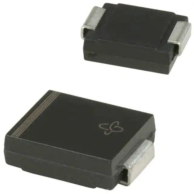
Part No.:
1.5SMC91CA-M3/9AT
Manufacturer:
Vishay General Semiconductor - Diodes Division
Category:
TVS Diodes
Package:
DO-214AB, SMC
Datasheet:
Aetrix1.5SMC91CA-M3/9AT.pdf
Description:
TVS DIODE 77.8VWM 125VC SMC
Quantity:
Payment:
Payment
Shipping:
Shipping

Inventory:4,714

Please send an inquiry. Send us your inquiry, and we will respond immediately.

Part Number
Quantity*
Price
Name*
Company
Email*
Comments

Product details

Overview

1.5SMC91CA-M3/9AT from Vishay General Semiconductor is a bidirectional surface-mount Transient Voltage Suppressor (TVS) diode in the SMC (DO-214AB) package, rated for 1500 W peak pulse power (10/1000 µs), with a standoff voltage of 77.8 V, clamping voltage of 125 V at 12.0 A, and operating junction temperature up to +150 °C. It protects signal lines and power rails in automotive sensor interfaces and industrial I/O modules against ESD, lightning-induced surges, and inductive switching transients.

For engineers reviewing the 1.5SMC91CA-M3/9AT datasheet, 1.5SMC91CA-M3/9AT pinout, 1.5SMC91CA-M3/9AT application, or 1.5SMC91CA-M3/9AT equivalent, this device is selected for high-energy transient suppression where bidirectional polarity, low clamping ratio (VC/VWM ≈ 1.6), halogen-free RoHS compliance, and AEC-Q101 qualification readiness are required.

Technical Context

This bidirectional TVS operates symmetrically across both polarities, delivering consistent clamping behavior during positive and negative transients without requiring polarity-aware PCB layout. Its glass-passivated junction ensures stable breakdown characteristics and low leakage (<1.0 µA at 77.8 V) over temperature and lifetime.

The device uses a planar silicon avalanche structure optimized for fast response (<1.0 ns), low incremental surge resistance, and repeatable energy handling under 0.01% duty-cycle 10/1000 µs pulses. Thermal resistance (RθJA = 75 °C/W) reflects its SMC package's ability to dissipate 6.5 W continuously when mounted on 8.0 mm × 8.0 mm copper pads.

Key Specifications

Parameter Value and Actual Design Meaning
VWM (Stand-off) 77.8 V - Maximum continuous reverse voltage before conduction begins; defines safe operating margin below clamping threshold.
VBR (Breakdown) 86.5–95.5 V at 1.0 mA - Verified avalanche onset range; ensures reliable triggering within specified tolerance band.
VC (Clamping) 125 V at 12.0 A - Peak voltage seen by protected circuit during 1500 W transient; determines downstream component stress.
PPPM 1500 W - Peak pulse power rating per 10/1000 µs waveform; quantifies single-event surge energy absorption capability.
IPPM 12.0 A - Corresponding peak pulse current at VC; used to size series impedance and verify protection coordination.
TJ max. +150 °C - Maximum junction temperature; enables operation in under-hood automotive or high-ambient industrial environments.
Package SMC (DO-214AB) - Standardized surface-mount outline with 3.2 mm min. creepage, compatible with automated placement and reflow.

Pinout & Package

SMC (DO-214AB) package: molded plastic body with coplanar matte tin-plated leads; no polarity marking for bidirectional configuration; terminals electrically symmetrical.

Pin/Terminal Circuit Role Design Meaning
Anode / Cathode (symmetrical) Bidirectional terminal pair Either lead serves as anode or cathode depending on transient polarity; no DC bias dependency; eliminates orientation errors during assembly.

Key Features

Feature Design Value
Bidirectional suppression Enables single-device protection of AC-coupled or floating signal paths (e.g., RS-485, CAN bus, sensor bridges) without external polarity management.
1500 W peak pulse rating Withstands IEC 61000-4-5 Level 4 surges (4 kV line-earth, 2 kV line-line) when properly decoupled, reducing need for cascaded protection stages.
Halogen-free, RoHS-compliant (M3 suffix) Meets IPC-1752A material declaration requirements and JEDEC J-STD-20 MSL level 1 (260 °C peak reflow), supporting green manufacturing and high-reliability assembly.
Low clamping ratio (VC/VWM ≈ 1.6) Minimizes overvoltage exposure to downstream ICs-critical for protecting 75 V-rated interface transceivers or 100 V MOSFET gates.
AEC-Q101 qualification path Base P/NHM3 variant supports automotive-grade validation (e.g., 1.5SMC91CAHM3_A/I); enables drop-in qualification upgrade without redesign.

Applications

Automotive Sensor Interface Industrial RS-485 Bus

Use Scenario: Protecting wheel speed, pressure, or temperature sensor outputs exposed to load-dump and ISO 7637-2 pulses in engine control units.

IC Role / Device Role / Timing Role: Bidirectional TVS placed at connector entry point to clamp ±100 V transients before reaching analog front-end or signal conditioner ICs.

Use Value: Prevents latch-up or gate oxide damage in precision amplifiers and ADC drivers by limiting voltage excursion to ≤125 V during 10/1000 µs surges.

Use Scenario: Safeguarding differential data lines in factory automation PLCs subjected to ground bounce and cable discharge events.

IC Role / Device Role / Timing Role: Common-mode transient suppressor across A/B lines, referenced to local ground, absorbing asymmetrical surges without disrupting DC bias.

Use Value: Maintains signal integrity during 4 kV contact ESD (IEC 61000-4-2) and prevents false triggering or communication lockup in half-duplex transceivers.

Telecom Power Input Consumer Appliance Motor Control

Use Scenario: Input-stage surge protection for PoE-powered network switches handling induced lightning surges on Ethernet cables.

IC Role / Device Role / Timing Role: Primary clamping device upstream of DC-DC converter, shunting energy before it reaches primary-side FETs or controller ICs.

Use Value: Limits input rail overshoot to <130 V during 1.5 kV ring-wave tests (IEC 61000-4-5), avoiding overvoltage shutdown or transformer insulation stress.

Use Scenario: Suppressing commutation spikes from brushed DC motors in smart home appliances (e.g., vacuum cleaners, washing machines).

IC Role / Device Role / Timing Role: Across motor terminals to absorb inductive kickback (L·di/dt) during PWM switching, protecting H-bridge MOSFETs and gate drivers.

Use Value: Reduces radiated emissions by clamping spikes to 125 V within <1 ns, easing EMC filter sizing and meeting CISPR 14-1 Class B limits.

Equivalent & Alternatives

The following parts are listed as comparable options for similar transient suppression applications.

Alternative Part Technical Difference Application Difference Selection Advice
SMBJ90CA Lower peak power (600 W), smaller SMB package (DO-214AA), VC = 129 V at 4.7 A Targeted at space-constrained consumer electronics with lower surge threat levels (e.g., USB ports, audio jacks) Select when board area is critical and IEC 61000-4-5 Level 3 (2 kV) suffices; not suitable for automotive or industrial mains-connected systems.
1.5KE91CA Through-hole TO-204AE (DO-201AE) package, same VWM/VC, but higher RθJA (100 °C/W) and manual assembly requirement Used in legacy industrial power supplies where wave soldering remains standard and rework tolerance is prioritized Choose only for through-hole production lines or prototyping; lacks SMT scalability and thermal performance of 1.5SMC91CA-M3/9AT.

Compared with SMBJ90CA and 1.5KE91CA, the 1.5SMC91CA-M3/9AT delivers superior energy handling in a compact, automated-assembly-ready package-making it optimal for new designs requiring AEC-Q101 readiness, high-density layouts, and robust Level 4 surge immunity.

Availability

1.5SMC91CA-M3/9AT is available at Aetrix Electronics and suitable for automotive sensor modules, industrial RS-485 networks, and telecom power inputs requiring stable component supply, halogen-free compliance, and long-term lifecycle continuity.

Supply support for 1.5SMC91CA-M3/9AT includes scheduled delivery planning, volume procurement assistance, BOM continuity management, traceable sourcing, and lifecycle availability coordination for OEM customers, industrial embedded developers, connected-device designers, and electronics production programs.

Manufacturer

Vishay General Semiconductor is a global leader in discrete semiconductors, specializing in diodes, rectifiers, TVS devices, and optoelectronics with emphasis on reliability, efficiency, and application-specific optimization.

The 1.5SMC Series was engineered for high-energy transient suppression in harsh environments-targeting automotive, industrial, and telecom systems where failure due to voltage surges must be eliminated without compromising footprint or manufacturability.

FAQ

What does the "CA" suffix indicate in 1.5SMC91CA-M3/9AT?

The "CA" suffix in 1.5SMC91CA-M3/9AT denotes a bidirectional configuration, meaning the device provides symmetrical transient suppression for both positive and negative voltage excursions. Unlike unidirectional variants (e.g., 1.5SMC91A), it has no cathode marking and functions identically regardless of polarity-ideal for AC-coupled or floating signal lines such as RS-485, CAN, or sensor bridge outputs.

Is 1.5SMC91CA-M3/9AT qualified to AEC-Q101?

The base 1.5SMC91CA-M3/9AT is commercial-grade and halogen-free (M3 suffix), but not AEC-Q101 qualified out-of-the-box. However, Vishay offers the automotive-qualified variant 1.5SMC91CAHM3_A/I, which shares identical electrical specs and SMC packaging while meeting AEC-Q101 stress test requirements-including temperature cycling, humidity bias HAST, and ESD robustness-enabling seamless qualification path for automotive designs.

What is the clamping voltage of 1.5SMC91CA-M3/9AT and why does it matter?

The clamping voltage (VC) of 1.5SMC91CA-M3/9AT is 125 V at 12.0 A (10/1000 µs waveform). This value represents the maximum voltage imposed on the protected circuit during a surge event. It matters because it directly determines whether downstream components-such as 100 V-rated transceivers or MOSFETs-remain within their absolute maximum ratings; a lower VC relative to VWM (clamping ratio ≈ 1.6) improves protection margin.

Can 1.5SMC91CA-M3/9AT replace 1.5SMC91A in an existing design?

No-1.5SMC91CA-M3/9AT cannot directly replace unidirectional 1.5SMC91A without circuit review. While both share identical VWM, VBR, and VC, the CA version is bidirectional and lacks polarity marking, making it unsuitable for DC-biased applications like power rail protection where cathode/anode orientation is critical. Use only where bidirectional symmetry is required and DC blocking is not needed.

What PCB layout guidance applies to 1.5SMC91CA-M3/9AT?

For optimal thermal and electrical performance, mount 1.5SMC91CA-M3/9AT on minimum 8.0 mm × 8.0 mm copper pads per terminal (per Vishay spec), use short, wide traces to minimize inductance, and avoid routing sensitive signals near its body. The SMC package requires no polarity alignment, but ensure solder mask clearance matches JEDEC DO-214AB standards to prevent bridging during reflow.

1.5SMC91CA-M3/9AT Specifications

Product attributes
Attribute value
Manufacturer:
Vishay General Semiconductor - Diodes Division
Package/Case:
DO-214AB, SMC
Series:
1.5SMC, TransZorb®
Packaging:
Tape & Reel (TR)
Product Status:
Active
Type:
Zener
Unidirectional Channels:
-
Bidirectional Channels:
1
Voltage - Reverse Standoff (Typ):
77.8V
Voltage - Breakdown (Min):
86.5V
Voltage - Clamping (Max) @ Ipp:
125V
Current - Peak Pulse (10/1000µs):
12A
Power - Peak Pulse:
1500W (1.5kW)
Power Line Protection:
No
Applications:
General Purpose
Capacitance @ Frequency:
-
Operating Temperature:
-65°C ~ 150°C (TJ)
Grade:
-
Qualification:
-
Mounting Type:
Surface Mount
Supplier Device Package:
DO-214AB (SMCJ)

1.5SMC91CA-M3/9AT FAQ

1.How can I place an order for 1.5SMC91CA-M3/9AT through Aetrix?

Please submit a Request for Quotation (RFQ) for 1.5SMC91CA-M3/9AT on Aetrix. Our sales agent will provide a competitive quotation and guide you through the order confirmation once you accept the terms.

2.Are the price and stock information for 1.5SMC91CA-M3/9AT reliable?

The price and inventory of 1.5SMC91CA-M3/9AT are updated periodically and may fluctuate due to market conditions. Stock and pricing data are typically refreshed every 24 hours. Quotation validity for 1.5SMC91CA-M3/9AT is usually 5 days.

3.What payment methods are accepted for 1.5SMC91CA-M3/9AT?

We accept Wire Transfer, PayPal, Credit Card, Western Union, MoneyGram, and Escrow for 1.5SMC91CA-M3/9AT transactions.

Note: Certain payment methods may incur a processing fee.

4.How is shipping managed for 1.5SMC91CA-M3/9AT?

1.5SMC91CA-M3/9AT orders can be shipped via leading logistics carriers, including DHL, UPS, FedEx, TNT, or Registered Mail.

Once your 1.5SMC91CA-M3/9AT order is processed, you will receive an email with the shipment details and tracking number.

Note: Tracking information may take up to 24 hours to appear. Express delivery typically takes 3–5 business days.

5.How can I obtain technical support or documentation for 1.5SMC91CA-M3/9AT?

For technical support, including 1.5SMC91CA-M3/9AT datasheets, pinout diagrams, or application guidance, please contact our engineering support team. They can provide detailed documentation and assistance for your 1.5SMC91CA-M3/9AT requirements.

6.How does Aetrix verify that 1.5SMC91CA-M3/9AT is sourced from the original manufacturer or authorized distributors?

All 1.5SMC91CA-M3/9AT products on Aetrix are procured from qualified distributors and authorized channels. Our dedicated quality assurance team conducts strict verification, including traceability checks and, if necessary, third-party testing. This ensures that 1.5SMC91CA-M3/9AT meets industry standards.

7.What is the process for return or replacement of 1.5SMC91CA-M3/9AT?

All 1.5SMC91CA-M3/9AT units undergo pre-shipment inspection (PSI). If there is an issue with 1.5SMC91CA-M3/9AT, returns or replacements are accepted under the following conditions:

1.Quantity discrepancies, incorrect items, or visible external defects (such as breakage or corrosion), acknowledged by Aetrix.

2.The issue is reported within 90 days of delivery.

3.The 1.5SMC91CA-M3/9AT part is unused and in its original packaging.

Return procedure for 1.5SMC91CA-M3/9AT:

1.Submit a request within 90 days.

2.Obtain a Return Material Authorization (RMA) from Aetrix.

1.5SMC91CA-M3/9AT Tags

  • 1.5SMC91CA-M3/9AT
  • 1.5SMC91CA-M3/9AT PDF
  • 1.5SMC91CA-M3/9AT Datasheet
  • 1.5SMC91CA-M3/9AT Specifications
  • 1.5SMC91CA-M3/9AT Images
  • Vishay General Semiconductor - Diodes Division
  • Vishay General Semiconductor - Diodes Division 1.5SMC91CA-M3/9AT
  • Buy 1.5SMC91CA-M3/9AT
  • 1.5SMC91CA-M3/9AT Price
  • 1.5SMC91CA-M3/9AT Distributor
  • 1.5SMC91CA-M3/9AT Supplier
  • 1.5SMC91CA-M3/9AT Wholesale
Related Products
ESD9B5.0ST5G
ESD9B5.0ST5G

onsemi

DESD3V3E1BL-7B
DESD3V3E1BL-7B

Diodes Incorporated

ESD5Z3.3T1G
ESD5Z3.3T1G

onsemi

D5V0H1B2LP-7B
D5V0H1B2LP-7B

Diodes Incorporated

D5V0P1B2LP-7B
D5V0P1B2LP-7B

Diodes Incorporated

DESD5V0U1BA-7
DESD5V0U1BA-7

Diodes Incorporated

ESD5Z5.0T1G
ESD5Z5.0T1G

onsemi

DESD5V0U1BB-7
DESD5V0U1BB-7

Diodes Incorporated

D12V0L1B2LP-7B
D12V0L1B2LP-7B

Diodes Incorporated

PESD2V0Y1BSFYL
PESD2V0Y1BSFYL

Nexperia USA Inc.

DF2S5M4CT,L3F
DF2S5M4CT,L3F

Toshiba Semiconductor and Storage

D5V0L1B2WS-7
D5V0L1B2WS-7

Diodes Incorporated

Tech Hub
Search

Search

PRODUCT

PRODUCT

PHONE

PHONE

USER

USER