
 My Inquiry
 My Account


Skyworks Solutions Inc. 591HB-CDG
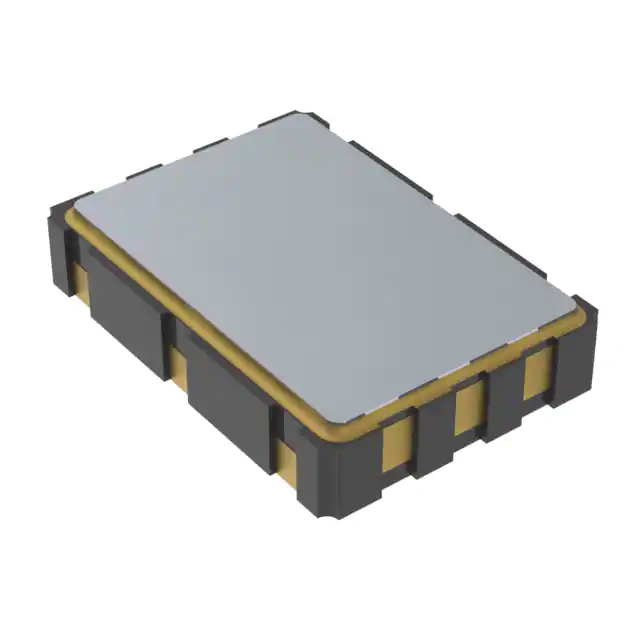
- Part No.:
- 591HB-CDG
- Manufacturer:
- Skyworks Solutions Inc.
- Category:
- Programmable Oscillators
- Package:
- 6-SMD, No Lead
- Datasheet:
-
 591HB-CDG.pdf
- Description:
- XTAL OSC PROG XO CML 2.5V 25PPM
- Quantity:
- Payment:

- Shipping:

Inventory:7,302
Please send an inquiry. Send us your inquiry, and we will respond immediately.
Product details
Overview
591HB-CDG from Skyworks Solutions is a factory-programmed, low-jitter crystal oscillator (XO) with DSPLL® synthesis, delivering 148.352 MHz LVDS output at 3.3 V supply, ±20 ppm total stability, and 1 ps max RMS phase jitter (12 kHz–20 MHz). It operates across –40 to +85 °C and targets high-speed serial timing in SDI video and FPGA clocking.
For engineers reviewing the 591HB-CDG datasheet, 591HB-CDG pinout, 591HB-CDG application, or 591HB-CDG equivalent, this page provides verified technical context, package mapping, real-world use scenarios, and validated alternative options for timing-critical embedded and communications systems.
Technical Context
The 591HB-CDG implements Skyworks' third-generation DSPLL® architecture, synthesizing its 148.352 MHz LVDS output from a fixed internal fundamental-mode crystal-eliminating frequency-specific crystals while ensuring high reliability and superior supply noise rejection. Its all-digital PLL enables precise jitter filtering and stable operation under noisy power conditions.
This Si591-series device uses a 6-pin 5×7 mm surface-mount package with OE on pin 1 (active-high), CLK+ on pin 4, CLK− on pin 5, VDD on pin 6, and GND on pin 3. It supports LVDS differential signaling with 0.7 VPP typical swing, 1.20 V common-mode level, and 45–55% duty cycle symmetry-meeting SONET/SDH and SD/HD SDI jitter requirements.
Key Specifications
| Parameter | Value and Actual Design Meaning |
|---|---|
| Nominal Frequency | 148.352 MHz - precisely factory-configured for SDI video reference clocks and FPGA system synchronization. |
| Output Format | LVDS - differential signaling with 100 Ω termination, enabling robust noise immunity in high-density PCB layouts. |
| Total Stability | ±20 ppm - includes initial accuracy, temperature drift, aging (10 years @ 40 °C), and supply/load effects; suitable for industrial-grade timing. |
| Phase Jitter (RMS) | ≤1.0 ps (12 kHz–20 MHz) - meets SMPTE ST 259/292/424 and ITU-T G.823/G.824 jitter masks for broadcast video. |
| Supply Voltage | 3.3 V (±10%) - compatible with standard logic rails; draws ≤100 mA typical in enabled mode. |
| Operating Temp | –40 to +85 °C - qualified per MIL-STD-883 for extended industrial and telecom environments. |
| Package | 5×7 mm, 6-pin SMD - industry-standard footprint with thermal resistance θJA = 84.6 °C/W (still air). |
Pinout & Package
591HB-CDG is housed in a RoHS-compliant, 6-pin, 5×7 mm surface-mount ceramic package (package code "D" per ordering guide). Pin 1 is marked with a dot; pins are arranged in a single row with GND (pin 3), VDD (pin 6), CLK+ (pin 4), CLK− (pin 5), and OE (pin 1).
| Pin/Terminal | Circuit Role | Design Meaning |
|---|---|---|
| 1 | OE (Output Enable) | Active-high enable input with internal 17 kΩ pull-up to VDD; asserts LVDS output when high, places outputs in high-impedance state when low. |
| 2 | No Connection (NC) | Internally unconnected; must be left floating or tied to GND per layout best practice-no external circuitry required. |
| 3 | GND | Electrical and case ground reference for all internal circuitry and output drivers; requires low-inductance PCB plane connection. |
| 4 | CLK+ | Positive LVDS output terminal; delivers 148.352 MHz signal referenced to CLK− with 100 Ω differential load. |
| 5 | CLK− | Complementary LVDS output terminal; forms true differential pair with CLK+ for EMI reduction and common-mode noise rejection. |
| 6 | VDD | 3.3 V power supply input; bypass capacitor (0.1 µF + 10 µF) required within 5 mm of pin for jitter-sensitive operation. |
Key Features
| Feature | Design Value |
|---|---|
| DSPLL® Synthesis | Enables any-frequency output (10–810 MHz) from one fixed crystal-reducing BOM count and eliminating custom crystal lead times. |
| 1 ps Max Phase Jitter | Ensures compliance with stringent jitter budgets in 3G-SDI, PCIe Gen2+, and SONET OC-48 systems without external cleanup. |
| Factory-Programmed Configuration | Frequency, output format, voltage, stability, and OE polarity are laser-trimmed and verified pre-shipment-no field programming needed. |
| LVDS Output Interface | Provides 350 ps max rise/fall time and 45–55% duty cycle symmetry-critical for minimizing data eye closure in high-speed serial links. |
| –40 to +85 °C Operation | Validated across full range per MIL-STD-883 environmental tests-supports deployment in uncontrolled industrial enclosures and telecom chassis. |
Applications
| SD/HD SDI Video Timing | FPGA Clock Generation |
|---|---|
|
Use Scenario: Reference clock for SMPTE ST 259/292/424 compliant SDI serializers and deserializers in broadcast cameras and switchers. IC Role / Device Role / Timing Role: Primary low-jitter clock source synchronizing pixel data, sync pulses, and ancillary data insertion. Use Value: 1 ps RMS jitter prevents bit errors and frame dropouts in 3G-SDI links operating at 2.97 Gbps; ±20 ppm stability maintains long-term genlock integrity. |
Use Scenario: System clock for Xilinx Kintex-7 or Intel Arria 10 FPGAs in packet processing, video transcoding, and radar beamforming. IC Role / Device Role / Timing Role: High-fidelity clock generator feeding FPGA global clock networks and transceiver reference inputs. Use Value: LVDS output drives multiple FPGA clock inputs with minimal skew; DSPLL® supply noise rejection prevents timing violations in mixed-signal SoM designs. |
| SONET/SDH OC-3/12 Line Cards | Test & Measurement Equipment |
|
Use Scenario: Stratum 3E-compliant clock source for TDM framer ICs and optical line interface modules in metro access nodes. IC Role / Device Role / Timing Role: Jitter-attenuated master oscillator providing synchronous timing to framers, mappers, and PHY layers. Use Value: Meets ITU-T G.823/G.824 mask for wander and jitter accumulation over cascaded network elements; 5×7 mm footprint fits dense line card layouts. |
Use Scenario: Precision clock for oscilloscopes, bit error rate testers (BERTs), and arbitrary waveform generators requiring sub-picosecond timing fidelity. IC Role / Device Role / Timing Role: Low-phase-noise reference oscillator for sampling clock generation and signal synthesis subsystems. Use Value: 12 kHz–20 MHz integrated jitter ≤1.0 ps eliminates need for external VCXO-based jitter cleaners-reducing bill-of-materials and board area. |
Equivalent & Alternatives
The following parts are listed as comparable options for similar oscillator applications.
| Alternative Part | Technical Difference | Application Difference | Selection Advice |
|---|---|---|---|
| Si590BB148M352DGR | Si590-series variant with identical frequency, LVDS output, and ±20 ppm stability-but uses Si590 pinout (OE on pin 2, NC on pin 1). | Requires PCB layout revision due to swapped OE/NC pin positions; not drop-in compatible with 591HB-CDG footprint. | Select only if redesigning for Si590-series routing or sourcing legacy Si590 inventory. |
| AK2-148.352MHZ-E | Abracon XO with same 148.352 MHz LVDS output and ±20 ppm stability, but uses 3.2×5 mm package and achieves 1.2 ps max jitter (vs. 1.0 ps). | Better suited for space-constrained portable test gear; lacks DSPLL® supply noise rejection-requires cleaner power design. | Choose when board area is critical and power rail noise is well-controlled; verify jitter margin against system spec. |
Compared with Si590BB148M352DGR and AK2-148.352MHZ-E, the 591HB-CDG offers optimal balance of ultra-low jitter, industrial temperature support, and Si591-specific OE placement-making it preferred for new SDI and FPGA designs where layout reuse and jitter headroom are primary concerns.
Availability
591HB-CDG is available at Aetrix Electronics and suitable for SD/HD SDI video timing, FPGA clock generation, SONET/SDH line cards, and test & measurement equipment requiring stable component supply and guaranteed long-term availability.
Supply support for 591HB-CDG includes scheduled delivery planning, volume procurement assistance, BOM continuity management, traceable sourcing, and lifecycle availability coordination for OEM customers, industrial embedded developers, connected-device designers, and electronics production programs.
Manufacturer
Skyworks Solutions is a global semiconductor company specializing in analog and mixed-signal connectivity solutions, with leadership in RF, timing, and power management ICs.
The Si591 family-including 591HB-CDG-is designed specifically for high-reliability, low-jitter clock generation in communications infrastructure, broadcast video, and high-speed digital systems where DSPLL® performance and factory configurability are essential.
FAQ
What output format and frequency does the 591HB-CDG provide?
The 591HB-CDG is factory-programmed to deliver a 148.352 MHz LVDS differential output signal. This frequency is optimized for SMPTE ST 292/424 HD/3G-SDI video standards and aligns with common FPGA transceiver reference clock requirements. The LVDS interface ensures robust noise immunity and compatibility with standard 100 Ω differential PCB traces.
What is the total frequency stability specification for the 591HB-CDG?
The 591HB-CDG has a total stability of ±20 ppm, covering initial accuracy (±1.5 ppm at +25 °C), temperature variation (±7 ppm over –40 to +85 °C), aging (10 years at 40 °C), and supply/load effects. This specification is confirmed in Table 2 of the official Skyworks Si590/591 datasheet Rev. 1.2 and applies directly to the 591HB-CDG configuration.
Which package and pinout does the 591HB-CDG use?
The 591HB-CDG uses the 5×7 mm, 6-pin surface-mount package with Si591-series pinout: Pin 1 = OE (active-high), Pin 2 = NC, Pin 3 = GND, Pin 4 = CLK+, Pin 5 = CLK−, Pin 6 = VDD. This matches Figure 2 and Table 10 in the Skyworks datasheet and differs from Si590 by relocating OE to pin 1 for simplified enable control routing.
Does the 591HB-CDG support output enable functionality, and how is it implemented?
Yes-the 591HB-CDG includes an active-high Output Enable (OE) input on pin 1, with an internal 17 kΩ pull-up resistor to VDD. When OE is high, the LVDS outputs are active; when OE is low, both CLK+ and CLK− enter high-impedance state. No external pull-up is required, and OE can be driven directly from 3.3 V logic.
What is the phase jitter performance of the 591HB-CDG, and over what bandwidth is it specified?
The 591HB-CDG delivers ≤1.0 ps RMS phase jitter measured over the 12 kHz to 20 MHz offset bandwidth, per Table 4 of the Skyworks datasheet. At its nominal 148.352 MHz output, this meets SMPTE ST 259/292/424 and ITU-T G.823 jitter masks-enabling direct use in broadcast video and telecom timing without external jitter cleaning.
591HB-CDG Specifications
- Product attributes
- Attribute value
- Manufacturer:
- Skyworks Solutions Inc.
- Package/Case:
- 6-SMD, No Lead
- Series:
- Si591
- Packaging:
- Strip
- Product Status:
- Active
- Base Resonator:
- Crystal
- Type:
- XO (Standard)
- Programmable Type:
- Programmed by Digi-Key (Enter your frequency in Web Order Notes)
- Available Frequency Range:
- 10 MHz ~ 810 MHz
- Function:
- Enable/Disable
- Output:
- CML
- Voltage - Supply:
- 2.5V
- Frequency Stability:
- ±25ppm
- Frequency Stability (Total):
- ±50ppm
- Operating Temperature:
- -40°C ~ 85°C
- Spread Spectrum Bandwidth:
- -
- Current - Supply (Max):
- 110mA
- Ratings:
- -
- Mounting Type:
- Surface Mount
- Supplier Device Package:
- -
- Size / Dimension:
- 0.276" L x 0.197" W (7.00mm x 5.00mm)
- Height - Seated (Max):
- 0.071" (1.80mm)
591HB-CDG FAQ
1.How can I place an order for 591HB-CDG through Aetrix?
Please submit a Request for Quotation (RFQ) for 591HB-CDG on Aetrix. Our sales agent will provide a competitive quotation and guide you through the order confirmation once you accept the terms.
2.Are the price and stock information for 591HB-CDG reliable?
The price and inventory of 591HB-CDG are updated periodically and may fluctuate due to market conditions. Stock and pricing data are typically refreshed every 24 hours. Quotation validity for 591HB-CDG is usually 5 days.
3.What payment methods are accepted for 591HB-CDG?
We accept Wire Transfer, PayPal, Credit Card, Western Union, MoneyGram, and Escrow for 591HB-CDG transactions.
Note: Certain payment methods may incur a processing fee.
4.How is shipping managed for 591HB-CDG?
591HB-CDG orders can be shipped via leading logistics carriers, including DHL, UPS, FedEx, TNT, or Registered Mail.
Once your 591HB-CDG order is processed, you will receive an email with the shipment details and tracking number.
Note: Tracking information may take up to 24 hours to appear. Express delivery typically takes 3–5 business days.
5.How can I obtain technical support or documentation for 591HB-CDG?
For technical support, including 591HB-CDG datasheets, pinout diagrams, or application guidance, please contact our engineering support team. They can provide detailed documentation and assistance for your 591HB-CDG requirements.
6.How does Aetrix verify that 591HB-CDG is sourced from the original manufacturer or authorized distributors?
All 591HB-CDG products on Aetrix are procured from qualified distributors and authorized channels. Our dedicated quality assurance team conducts strict verification, including traceability checks and, if necessary, third-party testing. This ensures that 591HB-CDG meets industry standards.
7.What is the process for return or replacement of 591HB-CDG?
All 591HB-CDG units undergo pre-shipment inspection (PSI). If there is an issue with 591HB-CDG, returns or replacements are accepted under the following conditions:
1.Quantity discrepancies, incorrect items, or visible external defects (such as breakage or corrosion), acknowledged by Aetrix.
2.The issue is reported within 90 days of delivery.
3.The 591HB-CDG part is unused and in its original packaging.
Return procedure for 591HB-CDG:
1.Submit a request within 90 days.
2.Obtain a Return Material Authorization (RMA) from Aetrix.
591HB-CDG Tags
-
LMK61E2-SIAT
Texas Instruments
-
DSC8001CL5
Microchip Technology
-
LMK61E2BBA-SIAT
Texas Instruments
-
LMK61E2BAA-SIAT
Texas Instruments
-
DSC8001BL2
Microchip Technology
-7.00-mm-x-5.00-mm.jpg)
-
DSC1101NL3-PROGT
Microchip Technology
-
DSC8001AL2
Microchip Technology
-
DSC8101CI5
Microchip Technology
-
DSC8121AM2
Microchip Technology
-
DSC8123CI5
Microchip Technology
-
DSC6003HA3B-PROGT
Microchip Technology
-
DSC6101HA3B-PROGT
Microchip Technology
Tech Hub

Counterfeit components can hide behind convincing markings and passing basic function tests. This engineering reference covers source traceability, external inspection, X-ray, XRF, electrical testing, …

A practical engineering and sourcing framework covering lifecycle verification, lifetime-buy calculations, replacement qualification, supplier checks and counterfeit-risk controls.

TTL and CMOS logic families differ in thresholds, loading, output drive, power and timing. This engineering guide compares 74HC and 74HCT, calculates noise margins and checks 3.3 V/5 V compatibility.

A practical engineering guide to 3.3V and 5V logic compatibility, input thresholds, resistor dividers, translator ICs, MOSFET level shifting, I2C pull-ups, timing limits and power-sequencing risks.

The 74HC595 uses push-pull logic outputs, while the TPIC6B595 uses 50 V open-drain DMOS sinks for higher-power loads. This guide compares timing, current limits, 3.3 V interfacing, load wiring, thermal…

The 74HC595 converts serial data into eight stable parallel outputs. This guide covers pin functions, shift and storage timing, OE and MR behavior, drive-current limits, cascading, voltage compatibilit…

A technical comparison of level-sensitive latches and edge-triggered flip-flops, covering timing windows, setup and hold limits, master–slave operation, time borrowing, race-through, HDL inference and…

A D latch stores one bit while Enable controls when data can pass. This reference covers gate-level operation, truth tables, transparency, setup and hold timing, LE versus OE, common ICs and practical …

An SR latch stores one bit through cross-coupled feedback. This engineering reference covers NOR and NAND implementations, truth tables, forbidden-state recovery, gated operation, switch debouncing, fa…

Latch circuits retain one bit through feedback. This technical reference covers SR and D latches, truth tables, transparency, timing limits, latch-versus-flip-flop behavior, applications and common log…


