
 My Inquiry
 My Account


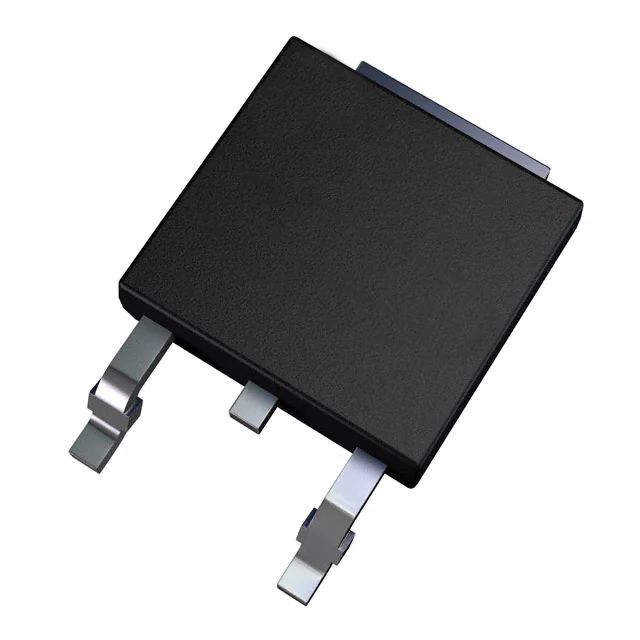
STMicroelectronics ACS110-7SB2

- Part No.:
- ACS110-7SB2
- Manufacturer:
- STMicroelectronics
- Category:
- TRIACs
- Package:
- 8-DIP (0.300", 7.62mm)
- Datasheet:
-
 ACS110-7SB2.pdf
- Description:
- TRIAC SENS GATE 700V 1A 8DIL
- Quantity:
- Payment:

- Shipping:

Inventory:1,197
Please send an inquiry. Send us your inquiry, and we will respond immediately.
Product details
Overview
ACS110-7SB2 from STMicroelectronics is a high-noise-immunity AC line switch in DIL-8 package, designed for solid-state replacement of electromechanical relays in appliance control. It features 700 V repetitive blocking voltage (VDRM/VRRM), 1 A RMS on-state current (IT(RMS)), <10 mA gate triggering current (IGT), and integrated avalanche clamping (VCL = 1100 V typ) to safely commutate inductive loads without external snubbers. Used in washing machine valve control and microwave oven defrost heater switching.
For engineers reviewing the ACS110-7SB2 datasheet, ACS110-7SB2 pinout, ACS110-7SB2 application, or ACS110-7SB2 equivalent, this page delivers verified thermal resistance (Rth(j-l) = 15 °C/W), static dV/dt >500 V/µs, I²t fusing capability (0.35 A²s), and direct microcontroller interface capability - all confirmed from ST's official April 2003 datasheet.
Technical Context
The ACS110-7SB2 implements ST's ASD™ (Advanced Switching Device) architecture, integrating a high-voltage clamping diode and gate-level shifter driver to isolate digital controllers from mains-referenced switching paths. Its negative-gate-triggering logic (gate current flows *out* of pin G) enables direct connection to MCU GPIO pins via a single series resistor.
It operates bidirectionally across AC line cycles, sustaining transient overvoltages up to 2 kV (per IEC 61000-4-5) without external protection. Turn-off energy from inductive loads (up to 10 mJ) is absorbed internally by the avalanche structure, eliminating need for varistors or RC snubbers in compliant designs.
Key Specifications
| Parameter | Value and Actual Design Meaning |
|---|---|
| VDRM / VRRM | ±700 V - Blocks full AC line peaks (e.g., 230 VAC × √2 ≈ 325 V) with 2.1× safety margin for surge immunity |
| IT(RMS) | 1 A at Tlead = 110 °C - Supports continuous resistive/inductive loads like 120 W fans or 230 V/1 A solenoids |
| VCL (typ) | 1100 V - Clamps turn-off inductive kick safely below breakdown, enabling snubberless operation |
| dV/dt (min) | 500 V/µs - Immune to fast transients common in motor-driven appliances and EMI-rich environments |
| Rth(j-l) | 15 °C/W - Enables thermal design with DIL-8 lead-frame heatsinking; supports 1 A conduction at ≤110 °C lead temp |
| I²t (tp=10ms) | 0.35 A²s - Quantifies single-pulse surge withstand; matches typical IEC 61000-4-5 test energy levels |
| IGT (max) | 10 mA - Compatible with standard MCU GPIO drive strength (e.g., STM32, ST72) without buffer stages |
Pinout & Package
DIL-8 package with exposed metal tab (pin 5) serving as thermal and electrical common reference. Pin 1 = Gate (G), Pins 2 & 4 = COM (common return), Pin 3 = OUT (switched output), Pin 5 = Tab (COM-connected thermal pad), Pins 6–8 = internal connections tied to COM.
| Pin/Terminal | Circuit Role | Design Meaning |
|---|---|---|
| Pin 1 (G) | Gate input | Negative-trigger input: requires current *sourced from* MCU pin (flows out of G); enables direct GPIO control |
| Pins 2 & 4 (COM) | Common reference | Return path for load current and gate circuit; electrically tied to thermal tab (Pin 5) |
| Pin 3 (OUT) | Switched output | Connects to load (e.g., solenoid coil); voltage swings ±700 V relative to COM during blocking |
| Pin 5 (Tab) | Thermal & electrical common | Exposed metal pad soldered to PCB copper; provides low-Rth(j-l) = 15 °C/W and ties to COM net |
Key Features
| Feature | Design Value |
|---|---|
| Integrated avalanche clamping | Clamps turn-off inductive energy (up to 10 mJ) internally-eliminates need for external snubber components |
| High noise immunity | Static dV/dt >500 V/µs ensures reliable operation in EMI-heavy appliance environments (e.g., motor commutation) |
| Direct microcontroller interface | 10 mA max IGT allows direct drive from standard MCU GPIOs without level-shifting or buffering circuitry |
| IEC 61000-4-5 compliance ready | Withstands 2 kV line-to-line surges per standard test circuit-reduces system-level certification effort |
| Snubberless inductive switching | Supports relay/solenoid loads up to 1 A RMS without external protection-cuts BOM count by up to 80% |
Applications
| Washing Machine Valve Control | Microwave Oven Defrost Heater |
|---|---|
Use Scenario: Precise on/off timing of water inlet valves during fill cycles, subject to vibration, humidity, and repeated thermal cycling. IC Role / Device Role / Timing Role: AC line switch replacing mechanical relay; handles 230 VAC, 0.5 A resistive-inductive valve coil with zero-crossing–independent turn-on. Use Value: Eliminates contact wear and bounce; enables silent, maintenance-free operation with 100,000+ cycle lifetime. | Use Scenario: Cycling defrost heater (230 VAC, ~1 A) during freezer compartment freeze-thaw cycles in frost-free refrigerators. IC Role / Device Role / Timing Role: Solid-state AC switch triggered by microcontroller PWM or timed pulses; sustains repeated inductive turn-off stress without degradation. Use Value: Prevents heater coil arcing and contact welding seen in relays; improves system reliability under condensation-prone conditions. |
| Dishwasher Solenoid Dispenser | Air Conditioning Fan Speed Control |
Use Scenario: Metered detergent dispensing via solenoid-actuated valve, requiring precise 100–500 ms pulse-width activation. IC Role / Device Role / Timing Role: High-dV/dt immune AC switch interfacing directly with dishwasher main controller; handles inductive kickback without gate feedback. Use Value: Removes need for flyback diodes or RC networks-reduces PCB area and component count while improving EMC performance. | Use Scenario: Two-speed fan control in split-system AC units, switching between low/high windings (230 VAC, 0.8 A each). IC Role / Device Role / Timing Role: Bidirectional AC switch managing phase-controlled or on/off fan winding selection; rated for 125 °C junction temperature. Use Value: Enables compact, sealed fan module design with no moving contacts-improves long-term dust/moisture resistance. |
Equivalent & Alternatives
The following parts are listed as comparable options for similar AC line switching applications.
| Alternative Part | Technical Difference | Application Difference | Selection Advice |
|---|---|---|---|
| ACS108-7SB2 | Lower IT(RMS) = 0.8 A; identical VDRM, package, and clamping voltage | Suitable only for sub-800 mA loads (e.g., small solenoids); reduced thermal margin at full ambient | Select when load current is consistently ≤0.8 A and board space/thermal budget is constrained |
| ACS120-7SB2 | Higher IT(RMS) = 1.2 A; same VDRM, package, and dV/dt rating | Supports heavier inductive loads (e.g., 250 W pumps); requires same PCB layout but higher thermal derating | Choose for future-proofing or systems with peak current spikes exceeding 1 A RMS |
Compared with ACS108-7SB2 and ACS120-7SB2, the ACS110-7SB2 offers optimal balance of 1 A RMS capacity, proven 15 °C/W thermal resistance in DIL-8, and documented IEC 61000-4-5 compliance-making it the preferred choice for mid-power appliance loads where reliability and certification efficiency are critical.
Availability
ACS110-7SB2 is available at Aetrix Electronics and suitable for washing machine valve control, microwave oven defrost heater switching, and dishwasher solenoid dispenser applications requiring stable component supply and long-term industrial availability.
Supply support for ACS110-7SB2 includes scheduled delivery planning, volume procurement assistance, BOM continuity management, traceable sourcing, and lifecycle availability coordination for OEM customers, industrial embedded developers, connected-device designers, and electronics production programs.
Manufacturer
STMicroelectronics is a global semiconductor leader headquartered in Geneva, Switzerland, specializing in power management, analog, and automotive-grade ICs with broad industrial qualification.
The ACS™ AC line switch product line was developed specifically for solid-state replacement of electromechanical relays in white goods and HVAC systems-emphasizing snubberless inductive switching, IEC-compliant surge ruggedness, and direct MCU interoperability.
FAQ
What is the correct gate drive configuration for ACS110-7SB2?
The ACS110-7SB2 requires negative gate triggering: current must flow *out* of the gate pin (Pin 1). Connect a resistor (e.g., 140 Ω) between MCU GPIO and Pin 1, with MCU GPIO pulled high (e.g., 3.3 V or 5 V) to block, and driven low to trigger. No external pull-down is needed-the device latches until current falls below IH (≤45 mA).
Can ACS110-7SB2 replace a mechanical relay in a 230 VAC, 1 A solenoid application?
Yes-ACS110-7SB2 is qualified for this use case. With 700 V VDRM, 1 A IT(RMS) at 110 °C lead temperature, and integrated clamping, it safely switches 230 VAC solenoids without snubbers. Confirm load inductance ≤10 H and ensure PCB copper area under Pin 5 meets ST's 5 cm² recommendation for thermal management.
Does ACS110-7SB2 require a heat sink in DIL-8 package?
No discrete heat sink is required if PCB layout follows ST's guidelines: ≥5 cm² copper area under Pin 5 (tab), 35 µm copper thickness, FR4 board. At 1 A RMS and 110 °C lead temperature, Rth(j-l) = 15 °C/W yields ~15 K rise above lead temp-well within 125 °C max junction limit. Forced air or larger copper improves margin.
How does ACS110-7SB2 handle IEC 61000-4-5 surge testing?
ACS110-7SB2 passes IEC 61000-4-5 Level 3 (2 kV line-to-line) when used with its specified test circuit (R = 150 Ω, L = 10 µH). The internal clamping structure limits voltage to ≤1100 V during transients, and the device sustains 10 such shocks per polarity. No external varistor is needed-compliance is achieved at the component level.
ACS110-7SB2 Specifications
- Product attributes
- Attribute value
- Manufacturer:
- STMicroelectronics
- Series:
- ASD™
- Package/Case:
- 8-DIP (0.300", 7.62mm)
- Packaging:
- Tube
- Product Status:
- Obsolete
- Triac Type:
- Logic - Sensitive Gate
- Voltage - Off State:
- 700 V
- Current - On State (It (RMS)) (Max):
- 1 A
- Voltage - Gate Trigger (Vgt) (Max):
- 1 V
- Current - Non Rep. Surge 50, 60Hz (Itsm):
- 8A, 11A
- Current - Gate Trigger (Igt) (Max):
- 10 mA
- Current - Hold (Ih) (Max):
- 45 mA
- Configuration:
- Single
- Operating Temperature:
- -30°C ~ 125°C (TJ)
- Grade:
- -
- Qualification:
- -
- Mounting Type:
- Through Hole
- Supplier Device Package:
- 8-DIL
ACS110-7SB2 FAQ
1.How can I place an order for ACS110-7SB2 through Aetrix?
Please submit a Request for Quotation (RFQ) for ACS110-7SB2 on Aetrix. Our sales agent will provide a competitive quotation and guide you through the order confirmation once you accept the terms.
2.Are the price and stock information for ACS110-7SB2 reliable?
The price and inventory of ACS110-7SB2 are updated periodically and may fluctuate due to market conditions. Stock and pricing data are typically refreshed every 24 hours. Quotation validity for ACS110-7SB2 is usually 5 days.
3.What payment methods are accepted for ACS110-7SB2?
We accept Wire Transfer, PayPal, Credit Card, Western Union, MoneyGram, and Escrow for ACS110-7SB2 transactions.
Note: Certain payment methods may incur a processing fee.
4.How is shipping managed for ACS110-7SB2?
ACS110-7SB2 orders can be shipped via leading logistics carriers, including DHL, UPS, FedEx, TNT, or Registered Mail.
Once your ACS110-7SB2 order is processed, you will receive an email with the shipment details and tracking number.
Note: Tracking information may take up to 24 hours to appear. Express delivery typically takes 3–5 business days.
5.How can I obtain technical support or documentation for ACS110-7SB2?
For technical support, including ACS110-7SB2 datasheets, pinout diagrams, or application guidance, please contact our engineering support team. They can provide detailed documentation and assistance for your ACS110-7SB2 requirements.
6.How does Aetrix verify that ACS110-7SB2 is sourced from the original manufacturer or authorized distributors?
All ACS110-7SB2 products on Aetrix are procured from qualified distributors and authorized channels. Our dedicated quality assurance team conducts strict verification, including traceability checks and, if necessary, third-party testing. This ensures that ACS110-7SB2 meets industry standards.
7.What is the process for return or replacement of ACS110-7SB2?
All ACS110-7SB2 units undergo pre-shipment inspection (PSI). If there is an issue with ACS110-7SB2, returns or replacements are accepted under the following conditions:
1.Quantity discrepancies, incorrect items, or visible external defects (such as breakage or corrosion), acknowledged by Aetrix.
2.The issue is reported within 90 days of delivery.
3.The ACS110-7SB2 part is unused and in its original packaging.
Return procedure for ACS110-7SB2:
1.Submit a request within 90 days.
2.Obtain a Return Material Authorization (RMA) from Aetrix.
ACS110-7SB2 Tags
-
Z0103NN5AA4
STMicroelectronics
-
Z0107MNT1G
Littelfuse Inc.
-
Z0103MNT1G
Littelfuse Inc.
;;2.jpg)
-
T405-800B-TR
STMicroelectronics
-
T835-600B-TR
STMicroelectronics
.JPG)
-
2N6073BG
Littelfuse Inc.
-
2N6075BG
Littelfuse Inc.
-
BTA08-600CWRG
STMicroelectronics

-
T835H-6G-TR
STMicroelectronics
-
BTA16-800BRG
STMicroelectronics
-
T1210-800G-TR
STMicroelectronics
-
MAC4DHMT4G
Littelfuse Inc.
Tech Hub

A practical engineering and sourcing framework covering lifecycle verification, lifetime-buy calculations, replacement qualification, supplier checks and counterfeit-risk controls.

TTL and CMOS logic families differ in thresholds, loading, output drive, power and timing. This engineering guide compares 74HC and 74HCT, calculates noise margins and checks 3.3 V/5 V compatibility.

A practical engineering guide to 3.3V and 5V logic compatibility, input thresholds, resistor dividers, translator ICs, MOSFET level shifting, I2C pull-ups, timing limits and power-sequencing risks.

The 74HC595 uses push-pull logic outputs, while the TPIC6B595 uses 50 V open-drain DMOS sinks for higher-power loads. This guide compares timing, current limits, 3.3 V interfacing, load wiring, thermal…

The 74HC595 converts serial data into eight stable parallel outputs. This guide covers pin functions, shift and storage timing, OE and MR behavior, drive-current limits, cascading, voltage compatibilit…

A technical comparison of level-sensitive latches and edge-triggered flip-flops, covering timing windows, setup and hold limits, master–slave operation, time borrowing, race-through, HDL inference and…

A D latch stores one bit while Enable controls when data can pass. This reference covers gate-level operation, truth tables, transparency, setup and hold timing, LE versus OE, common ICs and practical …

An SR latch stores one bit through cross-coupled feedback. This engineering reference covers NOR and NAND implementations, truth tables, forbidden-state recovery, gated operation, switch debouncing, fa…

Latch circuits retain one bit through feedback. This technical reference covers SR and D latches, truth tables, transparency, timing limits, latch-versus-flip-flop behavior, applications and common log…

An engineering guide to LED driver operation, constant-current and constant-voltage outputs, linear and switching topologies, dimming, IC selection, calculations, replacement compatibility, and fault c…


