
 My Inquiry
 My Account


Analog Devices Inc. ADIS16300AMLZ
- Part No.:
- ADIS16300AMLZ
- Manufacturer:
- Analog Devices Inc.
- Category:
- Multifunction
- Package:
- Datasheet:
-
 ADIS16300AMLZ.pdf
- Description:
- SENSOR MULT ACCELEROMETER/GYROSC
- Quantity:
- Payment:

- Shipping:

Inventory:2,499
Please send an inquiry. Send us your inquiry, and we will respond immediately.
Product details
Overview
ADIS16300AMLZ from Analog Devices is a four-degree-of-freedom inertial sensor module integrating a tri-axis MEMS accelerometer (±3 g), a yaw-axis gyroscope (±300°/sec), 13-bit pitch/roll inclinometer outputs, 330 Hz bandwidth, and SPI interface - deployed in robotics platform stabilization and medical instrument tilt sensing.
For engineers reviewing the ADIS16300AMLZ datasheet, ADIS16300AMLZ pinout, ADIS16300AMLZ application, or ADIS16300AMLZ equivalent, this page delivers verified technical context, real-world use-value mapping, factory-calibrated performance metrics, and validated alternative options for industrial inertial sensing integration.
Technical Context
The ADIS16300AMLZ implements a fully integrated inertial measurement unit (IMU) architecture with on-board signal conditioning, digital calibration compensation, and embedded temperature sensing. Its gyro and accelerometer data paths are independently digitized at 14 bits with factory-trimmed sensitivity, bias, and axis alignment coefficients stored in nonvolatile memory.
Digital control includes programmable sample rate (0.413–819.2 SPS), configurable digital filtering, self-test activation, auxiliary 12-bit ADC/DAC, and condition monitoring alarms. All motion data is delivered via SPI slave interface with burst-mode support for synchronized multi-register reads.
Key Specifications
| Parameter | Value and Actual Design Meaning |
|---|---|
| Gyroscope Range | ±300°/sec - supports high-dynamic rotational sensing in robotic joint feedback and navigation turn-rate estimation. |
| Accelerometer Range | ±3 g - enables full-scale linear acceleration capture for tilt, vibration, and impact detection in medical devices. |
| Bandwidth | 330 Hz - preserves fast transient response for platform stabilization loops without aliasing in closed-loop control. |
| Output Resolution | 14-bit gyro/accelerometer, 13-bit inclinometer - provides <0.05°/sec and <0.6 mg quantization for precision motion analysis. |
| Startup Time | 150 ms - ensures rapid system readiness after power-on, critical for portable diagnostic equipment boot sequences. |
| Supply Voltage | 4.75 V to 5.25 V - compatible with standard industrial 5 V rails; no external LDO required for stable operation. |
| Operating Temp | −40°C to +85°C - qualified for deployment in uncontrolled environments including field-deployed robotics and outdoor medical carts. |
Pinout & Package
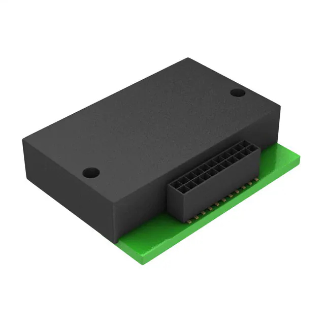
ADIS16300AMLZ uses a 24-lead surface-mount module (23 mm × 31 mm × 7.5 mm) with standard Samtec FTSH-112-03 mating connector interface, supporting horizontal or vertical PCB mounting via two screw holes.
| Pin/Terminal | Circuit Role | Design Meaning |
|---|---|---|
| 1, 7, 9 | DIO3 / DIO1 / DIO2 | Configurable digital I/O - used for alarm signaling, interrupt generation (e.g., DIO1 as new-data-ready pulse), or GPIO expansion. |
| 2 | DIO4/CLKIN | Sync clock input or digital I/O - accepts external timing reference up to 1.2 kHz for synchronized sampling across distributed sensors. |
| 3 | SCLK | SPI serial clock input - operates up to 2 MHz in normal mode; controls data transfer timing for register reads/writes. |
| 4 | DOUT | SPI data output - delivers 16-bit register contents on SCLK falling edge; supports burst-mode sequential read of nine registers. |
| 5 | DIN | SPI data input - accepts 16-bit command frames for register addressing and configuration writes (e.g., SMPL_PRD, GLOB_CMD). |
| 6 | CS | SPI chip select - active-low enable; wake-up pulse ≥20 μs required to exit sleep mode. |
| 8 | RST | Hardware reset input - asynchronous low pulse initiates full device reinitialization and factory calibration reload. |
| 10–12 | VCC | Primary power supply - supplies internal regulators for analog and digital blocks; requires 4.75–5.25 V with ≤100 mV ripple. |
| 13–15 | GND | Analog/digital ground reference - shared return path; layout best practice requires low-inductance connection to system ground plane. |
| 20 | AUX_DAC | 12-bit DAC output - provides programmable analog voltage (0–3.3 V) for biasing external circuitry or closed-loop actuator control. |
| 21 | AUX_ADC | 12-bit auxiliary ADC input - monitors external analog signals (e.g., battery voltage, temperature sensor) with 0.81 mV LSB resolution. |
Key Features
| Feature | Design Value |
|---|---|
| Factory-calibrated bias & sensitivity | Eliminates need for in-system calibration; each unit ships with unique correction coefficients for gyro/accelerometer axes. |
| Digitally controlled sample rate | Adjustable from 0.413 to 819.2 SPS via SMPL_PRD register - enables trade-off between latency, power, and bandwidth per application needs. |
| Programmable condition monitoring | Two independent alarm thresholds (ALM_MAG1/2) with sample-size control detect out-of-bounds motion events without host processor intervention. |
| Embedded temperature sensor | 12-bit output with 0.14°C/LSB scale factor - enables real-time thermal drift compensation of gyro/accelerometer readings. |
| Digital self-test | Activates internal mechanical stimulus; produces predictable output shifts (e.g., ±696 LSB gyro response) for functional verification pre-deployment. |
Applications
| Medical Instrumentation | Robotics |
|---|---|
Use Scenario: Real-time tilt monitoring in portable ultrasound carts and surgical positioning arms. IC Role / Device Role / Timing Role: Four-DoF inertial sensor providing pitch/roll angle and yaw-rate feedback for servo-controlled articulation. Use Value: Enables sub-degree tilt accuracy over −40°C to +85°C using factory-aligned axes and temperature-compensated outputs. |
Use Scenario: Joint-angle estimation and balance control in wheeled mobile robots and humanoid platforms. IC Role / Device Role / Timing Role: Autonomous IMU delivering synchronized gyro/accelerometer data at 819.2 SPS for Kalman filter fusion. Use Value: 330 Hz bandwidth and 150 ms startup time support responsive closed-loop stabilization without external timing sources. |
| Platform Control | Navigation |
Use Scenario: Stabilization of antenna mounts, camera gimbals, and inertial test fixtures. IC Role / Device Role / Timing Role: Inertial reference for servo drive error correction using DIO1-generated data-ready interrupts. Use Value: Tight orthogonal alignment (<±0.5° axis-to-frame) reduces software frame transformation overhead in embedded control firmware. |
Use Scenario: Dead-reckoning augmentation in GPS-denied indoor navigation systems. IC Role / Device Role / Timing Role: Low-drift yaw-rate and incline source feeding complementary filter algorithms alongside magnetometer data. Use Value: Angular random walk of 1.9°/√hr and in-run bias stability of 0.007°/sec enable accurate short-term heading hold. |
Equivalent & Alternatives
The following parts are listed as comparable options for similar inertial sensing applications.
| Alternative Part | Technical Difference | Application Difference | Selection Advice |
|---|---|---|---|
| ADIS16405AMLZ | 6-DoF (adds x/y gyro), higher performance (0.008°/sec bias stability), larger footprint (24.2 × 37.7 mm). | Required for full 6-axis motion capture; not drop-in due to pin count increase and different register map. | Select ADIS16405AMLZ only when x/y angular rate sensing is mandatory and board space allows. |
| ADIS16265AMLZ | 3-DoF (gyro-only), no accelerometer, lower cost, same package outline but different pinout (no AUX_ADC/DAC). | Suitable for pure yaw-rate applications like compass heading correction; lacks inclinometer and linear motion sensing. | Choose ADIS16265AMLZ when tilt and acceleration data are unnecessary and BOM cost is prioritized. |
Compared with ADIS16300AMLZ, ADIS16405AMLZ adds two gyro axes and improves bias stability by 87% but increases size and complexity, while ADIS16265AMLZ removes accelerometer functionality entirely-making ADIS16300AMLZ the optimal 4-DoF balance of capability, size, and integration effort.
Availability
ADIS16300AMLZ is available at Aetrix Electronics and suitable for robotics platform control, medical instrumentation tilt sensing, and industrial navigation systems requiring stable component supply with long-lifecycle support.
Supply support for ADIS16300AMLZ includes scheduled delivery planning, volume procurement assistance, BOM continuity management, traceable sourcing, and lifecycle availability coordination for OEM customers, industrial embedded developers, connected-device designers, and electronics production programs.
Manufacturer
Analog Devices is a global leader in high-performance analog, mixed-signal, and digital signal processing semiconductors, serving industrial, automotive, communications, and healthcare markets since 1965.
The ADIS16300AMLZ belongs to Analog Devices' iSensor® family of intelligent inertial modules, designed specifically for plug-and-play integration of calibrated motion sensing into resource-constrained embedded systems.
FAQ
What is the primary function of the ADIS16300AMLZ?
The ADIS16300AMLZ is a fully calibrated, four-degree-of-freedom inertial sensor module that integrates a yaw-axis gyroscope (±300°/sec), tri-axis accelerometer (±3 g), pitch/roll inclinometer, temperature sensor, and SPI interface. It delivers factory-trimmed motion data for immediate use in robotics, medical devices, and platform stabilization - eliminating the need for system-level calibration. The ADIS16300AMLZ performs all signal conditioning, digital processing, and memory storage internally.
Does the ADIS16300AMLZ support external clock synchronization?
Yes, the ADIS16300AMLZ supports external clock synchronization via Pin 2 (DIO4/CLKIN), which accepts a sync input clock up to 1.2 kHz. This enables precise timing alignment across multiple ADIS16300AMLZ units or with other system peripherals. When enabled, the external clock overrides the internal oscillator for sample timing, allowing deterministic data capture in distributed sensor networks - a key capability confirmed in the ADIS16300AMLZ timing specifications table.
How does the ADIS16300AMLZ handle factory calibration data?
The ADIS16300AMLZ stores factory calibration coefficients - including sensitivity, bias, and axial misalignment corrections - in nonvolatile flash memory. These values are automatically loaded at power-up and applied in real time to raw sensor outputs. Users can manually adjust offsets via GYRO_OFF and XACCL_OFF registers, trigger automatic bias nulling via GLOB_CMD, or restore original factory settings with a single command (GLOB_CMD[1] = 1). All flash operations for ADIS16300AMLZ are user-managed and require explicit execution.
Can the ADIS16300AMLZ operate from a 3.3 V supply?
No, the ADIS16300AMLZ requires a 4.75 V to 5.25 V supply on its VCC pins (10–12); it is not rated for 3.3 V operation. However, its digital I/O signals (SCLK, DIN, DOUT, CS, DIOx) are 5 V tolerant and driven from an internal 3.3 V rail, enabling direct interfacing with 3.3 V microcontrollers without level shifters. Powering the ADIS16300AMLZ outside its specified range risks invalidating factory calibration and may cause permanent damage per Absolute Maximum Ratings.
What is the purpose of the AUX_ADC and AUX_DAC pins on the ADIS16300AMLZ?
The AUX_ADC (Pin 21) is a 12-bit auxiliary analog-to-digital converter input with 0–3.3 V range and 0.81 mV LSB resolution, used to monitor external analog signals such as battery voltage or ambient temperature sensors. The AUX_DAC (Pin 20) is a 12-bit digital-to-analog converter output delivering 0–3.3 V, programmable via the AUX_DAC register, commonly employed for biasing external circuitry or generating control voltages in closed-loop systems - both features are integral to the ADIS16300AMLZ's system-level integration capability.
ADIS16300AMLZ Specifications
- Product attributes
- Attribute value
- Manufacturer:
- Analog Devices Inc.
- Series:
- iMEMS®, iSensor™
- Packaging:
- Tray
- Product Status:
- Obsolete
- Sensor Type:
- Accelerometer, Gyroscope
- Output Type:
- SPI
- Operating Temperature:
- -40°C ~ 85°C (TA)
ADIS16300AMLZ FAQ
1.How can I place an order for ADIS16300AMLZ through Aetrix?
Please submit a Request for Quotation (RFQ) for ADIS16300AMLZ on Aetrix. Our sales agent will provide a competitive quotation and guide you through the order confirmation once you accept the terms.
2.Are the price and stock information for ADIS16300AMLZ reliable?
The price and inventory of ADIS16300AMLZ are updated periodically and may fluctuate due to market conditions. Stock and pricing data are typically refreshed every 24 hours. Quotation validity for ADIS16300AMLZ is usually 5 days.
3.What payment methods are accepted for ADIS16300AMLZ?
We accept Wire Transfer, PayPal, Credit Card, Western Union, MoneyGram, and Escrow for ADIS16300AMLZ transactions.
Note: Certain payment methods may incur a processing fee.
4.How is shipping managed for ADIS16300AMLZ?
ADIS16300AMLZ orders can be shipped via leading logistics carriers, including DHL, UPS, FedEx, TNT, or Registered Mail.
Once your ADIS16300AMLZ order is processed, you will receive an email with the shipment details and tracking number.
Note: Tracking information may take up to 24 hours to appear. Express delivery typically takes 3–5 business days.
5.How can I obtain technical support or documentation for ADIS16300AMLZ?
For technical support, including ADIS16300AMLZ datasheets, pinout diagrams, or application guidance, please contact our engineering support team. They can provide detailed documentation and assistance for your ADIS16300AMLZ requirements.
6.How does Aetrix verify that ADIS16300AMLZ is sourced from the original manufacturer or authorized distributors?
All ADIS16300AMLZ products on Aetrix are procured from qualified distributors and authorized channels. Our dedicated quality assurance team conducts strict verification, including traceability checks and, if necessary, third-party testing. This ensures that ADIS16300AMLZ meets industry standards.
7.What is the process for return or replacement of ADIS16300AMLZ?
All ADIS16300AMLZ units undergo pre-shipment inspection (PSI). If there is an issue with ADIS16300AMLZ, returns or replacements are accepted under the following conditions:
1.Quantity discrepancies, incorrect items, or visible external defects (such as breakage or corrosion), acknowledged by Aetrix.
2.The issue is reported within 90 days of delivery.
3.The ADIS16300AMLZ part is unused and in its original packaging.
Return procedure for ADIS16300AMLZ:
1.Submit a request within 90 days.
2.Obtain a Return Material Authorization (RMA) from Aetrix.
ADIS16300AMLZ Tags
-
ISM303DACTR
STMicroelectronics
-
MS860702BA01-50
TE Connectivity Measurement Specialties
-
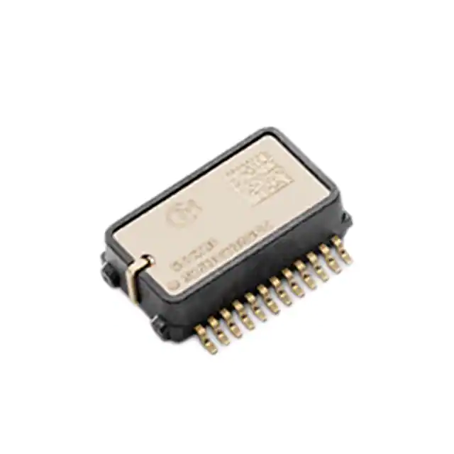
SCC2230-D08-05
Murata Electronics
-
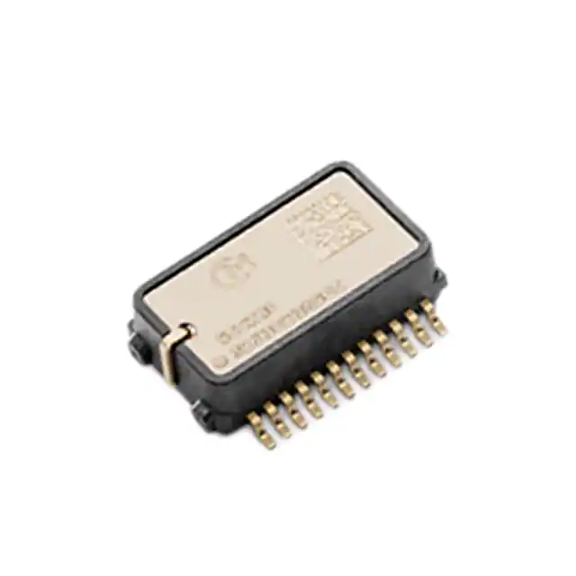
SCC2230-E02-05
Murata Electronics
-
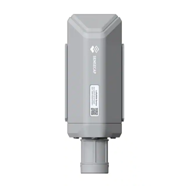
SCC2130-D08-05
Murata Electronics
-
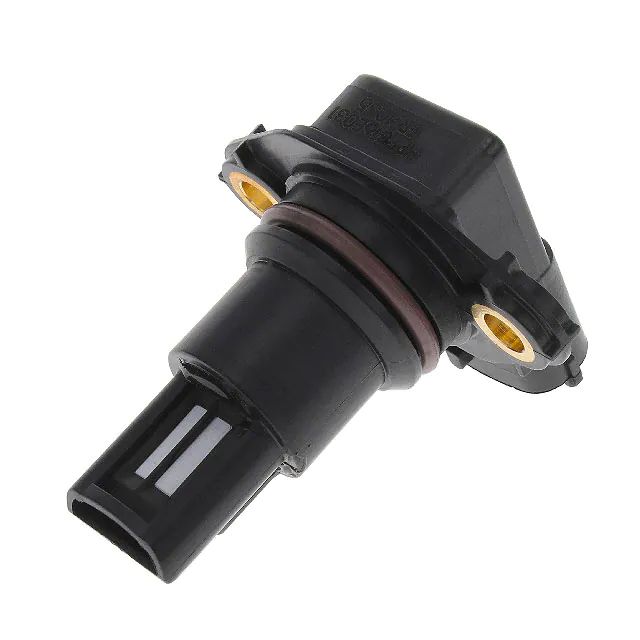
114992869
Seeed Technology Co., Ltd
-
HPP816E031
TE Connectivity Measurement Specialties
-
114992871
Seeed Technology Co., Ltd
-
CS-12S6SS-A
Advanced Thermal Solutions Inc.
-
QM30VT2
Banner Engineering Corporation

-
GE-2099
Amphenol Advanced Sensors (Thermometrics)
-
GE-2098
Amphenol Advanced Sensors (Thermometrics)
Tech Hub

A practical engineering guide to 3.3V and 5V logic compatibility, input thresholds, resistor dividers, translator ICs, MOSFET level shifting, I2C pull-ups, timing limits and power-sequencing risks.

The 74HC595 uses push-pull logic outputs, while the TPIC6B595 uses 50 V open-drain DMOS sinks for higher-power loads. This guide compares timing, current limits, 3.3 V interfacing, load wiring, thermal…

The 74HC595 converts serial data into eight stable parallel outputs. This guide covers pin functions, shift and storage timing, OE and MR behavior, drive-current limits, cascading, voltage compatibilit…

A technical comparison of level-sensitive latches and edge-triggered flip-flops, covering timing windows, setup and hold limits, master–slave operation, time borrowing, race-through, HDL inference and…

A D latch stores one bit while Enable controls when data can pass. This reference covers gate-level operation, truth tables, transparency, setup and hold timing, LE versus OE, common ICs and practical …

An SR latch stores one bit through cross-coupled feedback. This engineering reference covers NOR and NAND implementations, truth tables, forbidden-state recovery, gated operation, switch debouncing, fa…

Latch circuits retain one bit through feedback. This technical reference covers SR and D latches, truth tables, transparency, timing limits, latch-versus-flip-flop behavior, applications and common log…

An engineering guide to LED driver operation, constant-current and constant-voltage outputs, linear and switching topologies, dimming, IC selection, calculations, replacement compatibility, and fault c…

Operational amplifier guide covering op amp basics, feedback, ideal vs real op amps, common configurations, buffer circuits, offset, bias current, gain-bandwidth, slew rate, rail-to-rail limits and sel…

Jumper cables guide covering safe connection order, red and black clamp placement, final ground connection, cable gauge, length, clamp quality, copper vs CCA cables, jump starter comparison and battery…


