
 My Inquiry
 My Account


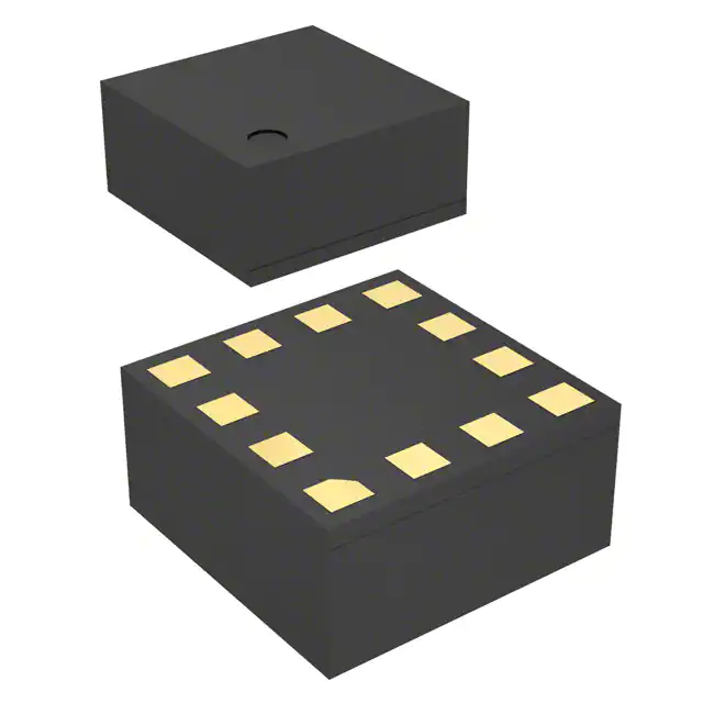
Analog Devices Inc. ADIS16470AMLZ
- Part No.:
- ADIS16470AMLZ
- Manufacturer:
- Analog Devices Inc.
- Category:
- IMUs (Inertial Measurement Units)
- Package:
- 44-BBGA Module
- Datasheet:
-
 ADIS16470AMLZ.pdf
- Description:
- 6 D0F PREC IMU 40G, 2000 DPS DNR
- Quantity:
- Payment:

- Shipping:

Inventory:114
Please send an inquiry. Send us your inquiry, and we will respond immediately.
Product details
Overview
ADIS16470AMLZ from Analog Devices is a miniature, factory-calibrated MEMS inertial measurement unit (IMU) integrating triaxial gyroscope (±2000°/sec), triaxial accelerometer (±40 g), and on-board signal conditioning. It delivers 8°/hr in-run bias stability, 0.008°/sec/√Hz rate noise density, and 13 μg accelerometer bias stability for high-accuracy motion sensing in navigation-grade industrial systems.
For engineers reviewing the ADIS16470AMLZ datasheet, ADIS16470AMLZ pinout, ADIS16470AMLZ application, or ADIS16470AMLZ equivalent, this page provides verified technical context, SPI interface timing constraints, delta-angle/delta-velocity output formats, factory calibration scope (−10°C to +75°C), and BGA-44 mechanical shock survivability (2000 g).
Technical Context
The ADIS16470AMLZ implements a dual-stage digital signal chain: gyroscopes sample at 4100 Hz and accelerometers at 4000 Hz, both decimated to a synchronized 2000 SPS output rate via Bartlett window FIR filtering and averaging/decimating stages. Factory calibration applies orthogonal alignment correction, linear-g compensation (gyro), and point-of-percussion correction (accelerometer), stored in nonvolatile flash memory.
It uses SPI Mode 3 (CPOL = 1, CPHA = 1) with 16-bit register addressing, supports external sync modes (direct/pulse/scaled/output), and includes hardware reset recovery (193 ms), data-ready (DR) signaling, and on-demand self-test for both inertial sensors and flash memory.
Key Specifications
| Parameter | Value and Actual Design Meaning |
|---|---|
| Gyroscope Range | ±2000°/sec - enables high-dynamic-range angular rate capture in UAV maneuvering or robotic arm control. |
| Accelerometer Range | ±40 g - supports impact detection and vibration monitoring in construction machinery and industrial automation. |
| In-Run Bias Stability | Gyro: 8°/hr; Accel: 13 μg - ensures long-duration drift performance critical for dead-reckoning navigation without GPS. |
| Rate Noise Density | 0.008°/sec/√Hz - defines minimum detectable angular motion, essential for precision stabilization in VR headsets. |
| Output Data Rate | 2000 SPS - provides deterministic timing for real-time closed-loop control in autonomous vehicle chassis systems. |
| Operating Temp | −25°C to +85°C - validated for deployment in outdoor robotics and agricultural equipment exposed to wide ambient swings. |
| Supply Voltage | 3.0 V to 3.6 V - compatible with standard industrial 3.3 V power rails and low-noise LDOs. |
| Shock Survivability | 2000 g - withstands mechanical stress during drop testing or heavy-equipment operation. |
Pinout & Package
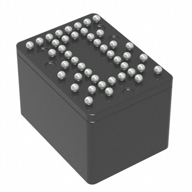
The ADIS16470AMLZ is housed in a 44-ball BGA package (ML-44-13), measuring 11 mm × 15 mm × 11 mm, with 24 ground balls, 8 VDD balls, and dedicated SPI, sync, reset, and data-ready terminals.
| Pin/Terminal | Circuit Role | Design Meaning |
|---|---|---|
| GND (A1–A8, B3–B6, C2, C6, D3, D6, E2, E6–E7, F1, F6–F8, G2, G7, H8, J2, J7, K1, K3, K8) | Power Ground | 24 dedicated ground balls ensure low-impedance return paths for analog and digital sections, minimizing noise coupling between gyro/accelerometer signal chains. |
| VDD (C7, D6, E3, H1, J4–J5, K6) | Power Supply | 8 distributed VDD balls support stable 3.3 V supply delivery across the die, reducing IR drop and improving thermal uniformity. |
| CS (G3) | SPI Chip Select | Active-low enable for SPI communication; requires ≥200 ns setup before first SCLK edge per timing spec. |
| SCLK (H6) | SPI Serial Clock | Accepts up to 2 MHz clock (1 MHz in burst mode); supports SPI Mode 3 (CPOL=1, CPHA=1) for synchronous register access. |
| DIN (G6) | SPI Data Input | Receives 16-bit register address/write data; requires 25 ns setup and 50 ns hold relative to SCLK rising edge. |
| DOUT (H3) | SPI Data Output | Drives calibrated sensor data or register contents; valid 25 ns after SCLK edge, compatible with 3.3 V logic levels. |
| DR (J6) | Data Ready Indicator | Active-high pulse signals availability of new 2000 SPS data in output registers-used for interrupt-driven acquisition. |
| SYNC (J3) | External Clock Input | Accepts direct/pulse/scaled/external sync signals (1.9–2.1 kHz typical) to synchronize internal processing rate to host system timing. |
| RST (F3) | Hardware Reset | Active-high pulse ≥1 μs initiates full device reset; recovery completes in 193 ms with DR pulsing resuming thereafter. |
Key Features
| Feature | Design Value |
|---|---|
| Factory Calibration | Full sensitivity, bias, axial misalignment, linear-g (gyro), and point-of-percussion (accel) corrections applied across −10°C to +75°C - eliminates need for field calibration in most industrial deployments. |
| Delta-Angle/Delta-Velocity Outputs | Integrated angular displacement (°) and linear velocity change (m/sec) outputs - reduces host MCU computational load in navigation algorithms. |
| On-Demand Self-Test | Separate commands verify inertial sensor functionality and flash memory integrity - enables runtime diagnostics in safety-critical autonomous systems. |
| Programmable Filtering | Bartlett window FIR and configurable decimation (via DEC_RATE register) allow trade-off between bandwidth (up to 550 Hz gyro / 600 Hz accel) and noise reduction. |
| Single-Supply Operation | 3.0 V to 3.6 V operation with 42–50 mA normal-mode current - simplifies power design versus dual-supply IMUs and avoids level-shifting circuitry. |
Applications
| Navigation & Stabilization | Unmanned Vehicles |
|---|---|
Use Scenario: High-precision attitude estimation in GNSS-denied environments such as underground mining or indoor warehouses. IC Role / Device Role / Timing Role: Primary inertial sensor providing time-synchronized delta-angle and delta-velocity updates at 2000 SPS to fusion filter. Use Value: 8°/hr gyro bias stability and 13 μg accel bias stability minimize position drift over extended periods without external reference. | Use Scenario: Real-time roll/pitch/yaw control for quadcopter flight controllers during aggressive maneuvers. IC Role / Device Role / Timing Role: Core motion sensor feeding closed-loop PID controllers with deterministic 500 μs update latency (2000 SPS). Use Value: ±2000°/sec gyro range and 2000 g shock survivability sustain accuracy during rapid acceleration and mechanical stress. |
| Industrial Robotics | Augmented Reality |
Use Scenario: Joint angle feedback and end-effector motion tracking in collaborative robot arms operating near humans. IC Role / Device Role / Timing Role: Embedded IMU delivering calibrated angular rate and acceleration data to safety-rated motion monitoring firmware. Use Value: Tight orthogonal alignment (±0.1°) and factory temperature compensation reduce frame transformation errors in kinematic models. | Use Scenario: Head orientation tracking in tethered VR headsets requiring sub-degree latency and jitter-free rendering. IC Role / Device Role / Timing Role: Low-latency motion sensor supplying delta-angle outputs directly to GPU pose prediction pipeline. Use Value: 0.008°/sec/√Hz rate noise density and 550 Hz gyro bandwidth preserve fine head-motion fidelity without oversmoothing. |
Equivalent & Alternatives
The following parts are listed as comparable options for similar inertial measurement applications.
| Alternative Part | Technical Difference | Application Difference | Selection Advice |
|---|---|---|---|
| ADIS16475-3AMLZ | Higher gyro bias stability (2°/hr vs. 8°/hr), wider temp range (−40°C to +105°C), same BGA-44 package and SPI interface. | Targeted at aerospace and defense where ultra-low drift is mandatory; requires tighter thermal management due to higher power. | Select ADIS16475-3AMLZ when <2°/hr gyro bias stability is required and extended temperature operation justifies cost premium. |
| ICM-20948 | Lower-cost 9-DoF IMU (gyro/accel/mag), no factory calibration, 16-bit outputs only, 3.3 V supply, QFN-24 package. | Suitable for consumer drones and wearables where cost and size dominate; lacks navigation-grade stability and temperature compensation. | Choose ICM-20948 for cost-sensitive, non-safety-critical applications where system-level calibration is feasible. |
Compared with ADIS16470AMLZ, ADIS16475-3AMLZ offers superior drift performance and extended temperature capability but at higher cost and power, while ICM-20948 provides compact size and lower price but requires full system-level calibration and delivers lower stability metrics.
Availability
ADIS16470AMLZ is available at Aetrix Electronics and suitable for unmanned vehicle guidance, industrial robotic motion control, and augmented reality headset development requiring stable component supply and long-term production continuity.
Supply support for ADIS16470AMLZ includes scheduled delivery planning, volume procurement assistance, BOM continuity management, traceable sourcing, and lifecycle availability coordination for OEM customers, industrial embedded developers, connected-device designers, and electronics production programs.
Manufacturer
Analog Devices is a global semiconductor leader specializing in high-performance analog, mixed-signal, and digital signal processing technologies for precision measurement and control.
The ADIS16470AMLZ belongs to Analog Devices' iSensor® MEMS IMU product line, engineered for industrial-grade inertial sensing where factory calibration, temperature stability, and mechanical robustness are critical for navigation and stabilization systems.
FAQ
What is the factory calibration temperature range for the ADIS16470AMLZ?
The ADIS16470AMLZ undergoes full factory calibration across −10°C to +75°C, covering sensitivity, bias, axial misalignment, linear-g effect (gyro), and point-of-percussion (accelerometer). These corrections are stored in on-chip flash and applied automatically during operation, enabling accurate performance without user calibration in that range. The ADIS16470AMLZ operates from −25°C to +85°C, with specifications guaranteed at TC = 25°C.
Does the ADIS16470AMLZ support external synchronization, and what modes are available?
Yes, the ADIS16470AMLZ supports external synchronization via the SYNC pin (J3) with four configurable modes: direct, pulse, scaled, and output. These are selected using bits [4:2] of the MSC_CTRL register. Direct and pulse modes accept external clocks (1.9–2.1 kHz typical) to align internal sampling to host system timing, enabling deterministic multi-sensor synchronization in distributed control systems.
What is the meaning of delta-angle and delta-velocity outputs in the ADIS16470AMLZ?
The ADIS16470AMLZ provides integrated delta-angle (in degrees) and delta-velocity (in meters/sec) outputs - computed internally by integrating raw gyroscope and accelerometer data over each 500 μs sample period (2000 SPS). These outputs reduce host processor computation load in navigation algorithms and improve timing determinism compared to integrating raw sensor streams in firmware.
How does the ADIS16470AMLZ handle self-test, and what components can be verified?
The ADIS16470AMLZ supports two independent on-demand self-tests: one for inertial sensors (gyros and accelerometers) and another for flash memory. Initiated via the GLOB_CMD register (Bit 2 for sensors, Bit 4 for flash), each test executes in ≤14 ms (sensor) or ≤32 ms (flash) and reports pass/fail status in diagnostic registers. This enables runtime health verification in safety-aware industrial and autonomous systems without disrupting normal operation.
What are the power supply requirements and current consumption of the ADIS16470AMLZ?
The ADIS16470AMLZ operates from a single 3.0 V to 3.6 V supply, drawing 42–50 mA in normal mode at VDD = 3.3 V. During power-on start-up or hardware reset, supply current transients may reach 250 mA for brief intervals. The device includes 8 VDD and 24 GND balls in its BGA-44 package to maintain stable voltage distribution and minimize noise coupling across analog and digital domains.
ADIS16470AMLZ Specifications
- Product attributes
- Attribute value
- Manufacturer:
- Analog Devices Inc.
- Series:
- -
- Package/Case:
- 44-BBGA Module
- Packaging:
- Tray
- Product Status:
- Active
- Sensor Type:
- Accelerometer, Gyroscope, 6 Axis
- Output Type:
- SPI
- Operating Temperature:
- -25°C ~ 85°C
- Grade:
- -
- Qualification:
- -
- Supplier Device Package:
- 44-BGA Module
- Mounting Type:
- Surface Mount
ADIS16470AMLZ FAQ
1.How can I place an order for ADIS16470AMLZ through Aetrix?
Please submit a Request for Quotation (RFQ) for ADIS16470AMLZ on Aetrix. Our sales agent will provide a competitive quotation and guide you through the order confirmation once you accept the terms.
2.Are the price and stock information for ADIS16470AMLZ reliable?
The price and inventory of ADIS16470AMLZ are updated periodically and may fluctuate due to market conditions. Stock and pricing data are typically refreshed every 24 hours. Quotation validity for ADIS16470AMLZ is usually 5 days.
3.What payment methods are accepted for ADIS16470AMLZ?
We accept Wire Transfer, PayPal, Credit Card, Western Union, MoneyGram, and Escrow for ADIS16470AMLZ transactions.
Note: Certain payment methods may incur a processing fee.
4.How is shipping managed for ADIS16470AMLZ?
ADIS16470AMLZ orders can be shipped via leading logistics carriers, including DHL, UPS, FedEx, TNT, or Registered Mail.
Once your ADIS16470AMLZ order is processed, you will receive an email with the shipment details and tracking number.
Note: Tracking information may take up to 24 hours to appear. Express delivery typically takes 3–5 business days.
5.How can I obtain technical support or documentation for ADIS16470AMLZ?
For technical support, including ADIS16470AMLZ datasheets, pinout diagrams, or application guidance, please contact our engineering support team. They can provide detailed documentation and assistance for your ADIS16470AMLZ requirements.
6.How does Aetrix verify that ADIS16470AMLZ is sourced from the original manufacturer or authorized distributors?
All ADIS16470AMLZ products on Aetrix are procured from qualified distributors and authorized channels. Our dedicated quality assurance team conducts strict verification, including traceability checks and, if necessary, third-party testing. This ensures that ADIS16470AMLZ meets industry standards.
7.What is the process for return or replacement of ADIS16470AMLZ?
All ADIS16470AMLZ units undergo pre-shipment inspection (PSI). If there is an issue with ADIS16470AMLZ, returns or replacements are accepted under the following conditions:
1.Quantity discrepancies, incorrect items, or visible external defects (such as breakage or corrosion), acknowledged by Aetrix.
2.The issue is reported within 90 days of delivery.
3.The ADIS16470AMLZ part is unused and in its original packaging.
Return procedure for ADIS16470AMLZ:
1.Submit a request within 90 days.
2.Obtain a Return Material Authorization (RMA) from Aetrix.
ADIS16470AMLZ Tags

-
BMI323
Bosch Sensortec
-
ICM-42670-P
TDK InvenSense
-
ICM-42605
TDK InvenSense

-
LSM6DSO32TR
STMicroelectronics
-
LSM6DSOTR
STMicroelectronics
-
LSM6DSVTR
STMicroelectronics
-
LSM6DSRTR
STMicroelectronics
-
BMI270
Bosch Sensortec
-
LSM6DSOXTR
STMicroelectronics
-
LSM6DSV16XTR
STMicroelectronics
-
LSM6DSO16ISTR
STMicroelectronics
-
LSM303AGRTR
STMicroelectronics
Tech Hub

A practical engineering guide to 3.3V and 5V logic compatibility, input thresholds, resistor dividers, translator ICs, MOSFET level shifting, I2C pull-ups, timing limits and power-sequencing risks.

The 74HC595 uses push-pull logic outputs, while the TPIC6B595 uses 50 V open-drain DMOS sinks for higher-power loads. This guide compares timing, current limits, 3.3 V interfacing, load wiring, thermal…

The 74HC595 converts serial data into eight stable parallel outputs. This guide covers pin functions, shift and storage timing, OE and MR behavior, drive-current limits, cascading, voltage compatibilit…

A technical comparison of level-sensitive latches and edge-triggered flip-flops, covering timing windows, setup and hold limits, master–slave operation, time borrowing, race-through, HDL inference and…

A D latch stores one bit while Enable controls when data can pass. This reference covers gate-level operation, truth tables, transparency, setup and hold timing, LE versus OE, common ICs and practical …

An SR latch stores one bit through cross-coupled feedback. This engineering reference covers NOR and NAND implementations, truth tables, forbidden-state recovery, gated operation, switch debouncing, fa…

Latch circuits retain one bit through feedback. This technical reference covers SR and D latches, truth tables, transparency, timing limits, latch-versus-flip-flop behavior, applications and common log…

An engineering guide to LED driver operation, constant-current and constant-voltage outputs, linear and switching topologies, dimming, IC selection, calculations, replacement compatibility, and fault c…

Operational amplifier guide covering op amp basics, feedback, ideal vs real op amps, common configurations, buffer circuits, offset, bias current, gain-bandwidth, slew rate, rail-to-rail limits and sel…

Jumper cables guide covering safe connection order, red and black clamp placement, final ground connection, cable gauge, length, clamp quality, copper vs CCA cables, jump starter comparison and battery…


