
 My Inquiry
 My Account


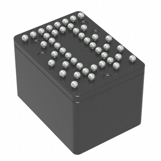
Analog Devices Inc. ADIS16477-2BMLZ
- Part No.:
- ADIS16477-2BMLZ
- Manufacturer:
- Analog Devices Inc.
- Category:
- IMUs (Inertial Measurement Units)
- Package:
- 44-BBGA Module
- Datasheet:
-
 ADIS16477-2BMLZ.pdf
- Description:
- 6 DOF PREC IMU, 40G (500 DPS DNR
- Quantity:
- Payment:

- Shipping:

Inventory:4,138
Please send an inquiry. Send us your inquiry, and we will respond immediately.
Product details
Overview
ADIS16477-2BMLZ from Analog Devices is a precision, miniature MEMS inertial measurement unit (IMU) integrating triaxial gyroscope (±500°/sec range), triaxial accelerometer (±40 g), delta angle/delta velocity outputs, and factory calibration for sensitivity, bias, and axis alignment. It delivers 2.5°/hr in-run bias stability, 0.15°/√hr angular random walk, and operates from −40°C to +105°C with SPI interface - used in high-accuracy navigation and stabilization systems for autonomous vehicles and industrial robotics.
For engineers reviewing the ADIS16477-2BMLZ datasheet, ADIS16477-2BMLZ pinout, ADIS16477-2BMLZ application, or ADIS16477-2BMLZ equivalent, key selection criteria include its ±500°/sec gyroscope range, 2000 SPS update rate, 44-ball BGA package (11 mm × 15 mm × 11 mm), 3.0–3.6 V single-supply operation, and support for external sync modes (direct/pulse/scaled).
Technical Context
The ADIS16477-2BMLZ implements a dual-stage digital signal chain: gyroscopes sample at 4100 Hz and accelerometers at matched rates, both processed to 2000 SPS output registers using internal clocking or configurable external SYNC input. Factory calibration applies matrix-based corrections for scale, misalignment, linear g effect (gyro), and point-of-percussion (accelerometer), stored in flash and applied in real time.
It features programmable Bartlett window FIR filtering and decimation via FILT_CTRL and DEC_RATE registers, supports burst read modes (16-/32-bit), and includes on-demand self-test for inertial sensors and flash memory. The device uses SPI Mode 3 (CPOL=1, CPHA=1) with data-ready (DR) signaling for deterministic acquisition timing.
Key Specifications
| Parameter | Value and Actual Design Meaning |
|---|---|
| Gyroscope Range | ±500°/sec - enables high-dynamic-range motion capture without saturation in aggressive maneuvering or vibration environments. |
| In-Run Bias Stability | 2.5°/hr - ensures minimal drift during extended operation critical for dead-reckoning navigation over minutes. |
| Angular Random Walk | 0.15°/√hr - defines low-frequency noise floor limiting orientation accuracy over short integration times. |
| Accelerometer Range | ±40 g - supports shock survivability up to 2000 g and captures high-acceleration events in construction machinery or UAV launch. |
| Data Update Rate | 2000 SPS - provides fine temporal resolution for real-time control loops in robotics and stabilization platforms. |
| Operating Temperature | −40°C to +105°C - qualifies for under-hood automotive, industrial enclosures, and outdoor unmanned systems. |
| Supply Voltage | 3.0 V to 3.6 V - compatible with standard industrial 3.3 V rails; power supply current is 44–55 mA in normal mode. |
| Package | 44-ball BGA, 11 mm × 15 mm × 11 mm - compact footprint with thermal resistance θJA = 158.2°C/W for PCB-integrated thermal management. |
Pinout & Package
The ADIS16477-2BMLZ is housed in a 44-ball ball grid array (BGA) package (ML-44-13), measuring 11 mm × 15 mm × 11 mm, with exposed thermal pad and 0.8 mm ball pitch. Pin assignments follow bottom-view layout per Figure 6 of Rev. E datasheet.
| Pin/Terminal | Circuit Role | Design Meaning |
|---|---|---|
| GND (A1–A8, B3–B6, C2, C6, D3, D6, E2, E6–E7, F1, F6–F8, G2, G7, H8, J2, J7, K1, K3, K8) | Power Ground | 29 dedicated ground balls ensure low-impedance return paths, reduce noise coupling, and support thermal dissipation via internal thermal pad connection. |
| VDD (C7, D6, E3, H1, J4–J5, K6) | Power Supply | 7 supply balls distribute current across package to minimize IR drop and voltage ripple at 44–55 mA operating load. |
| CS (G3) | SPI Chip Select | Active-low enable for SPI communication; must be asserted before SCLK edge to initiate register access. |
| DIN (G6) | SPI Data Input | Accepts 16-bit or 32-bit register write commands; setup/hold times require tDSU ≥ 25 ns and tDHD ≥ 50 ns relative to SCLK rising edge. |
| DOUT (H3) | SPI Data Output | Provides readback of sensor data or register contents; valid within tDAV ≤ 25 ns after SCLK edge. |
| SCLK (H6) | SPI Serial Clock | Supports up to 2 MHz in normal mode; timing requires tSCLKR/tSCLKF ≤ 12.5 ns for reliable edge detection. |
| SYNC (J3) | External Clock Input | Accepts direct/pulse/scaled sync signals (1.9–2.1 kHz typical) to synchronize internal processing rate and eliminate jitter in multi-sensor systems. |
| DR (J6) | Data Ready Output | Active-high pulse indicates new 2000 SPS data is available in output registers; used for interrupt-driven acquisition. |
| RST (F3) | Reset Input | Asynchronous active-low reset; requires ≥1 µs pulse width and ≥10 µs low state for full recovery (193 ms). |
Key Features
| Feature | Design Value |
|---|---|
| Factory-calibrated inertial sensors | Full 3×3 scale/alignment matrices, bias offsets, linear g compensation (gyro), and point-of-percussion correction (accel) stored in flash and applied automatically - eliminates field calibration effort. |
| Triaxial delta angle & delta velocity outputs | Integrated angular displacement (°) and linear velocity change (m/sec) computed onboard - reduces host processor load and latency in closed-loop control. |
| Programmable Bartlett window FIR filter | Configurable via FILT_CTRL register to suppress aliasing and mechanical resonance without external components - improves signal integrity in high-vibration environments. |
| On-demand self-test | Separate diagnostic routines for inertial sensors (electromechanical excitation) and flash memory (CRC check) - enables runtime health verification per IEC 61508 SIL2 requirements. |
| External sync modes | Direct, pulse, scaled, and output sync options via MSC_CTRL[4:2] - allows precise time-coordination with GPS PPS, camera triggers, or other IMUs in distributed systems. |
| Single-supply 3.3 V operation | Eliminates need for dual-rail supplies; integrated LDO-like regulation maintains stable core voltage across 3.0–3.6 V input range - simplifies power design in space-constrained modules. |
Applications
| Autonomous Mobile Robots | High-Precision Agricultural Guidance |
|---|---|
Use Scenario: Real-time attitude estimation and path-following control for GNSS-denied indoor/outdoor navigation. IC Role / Device Role / Timing Role: Primary inertial reference providing 2000 SPS delta angle updates to fusion algorithm; DR signal synchronizes with MCU timer interrupts. Use Value: 2.5°/hr bias stability enables <1° heading drift over 20 minutes, supporting sub-meter positioning without external aiding. |
Use Scenario: Centimeter-level implement steering on tractors operating on uneven terrain with variable vibration profiles. IC Role / Device Role / Timing Role: Motion reference for hydraulic actuator feedback loop; external pulse sync aligns IMU sampling with wheel encoder edges. Use Value: ±40 g accelerometer range and 2000 g shock survivability maintain functionality during pothole impacts and rapid direction changes. |
| Industrial Stabilization Platforms | Unmanned Aerial Vehicle (UAV) Autopilot |
Use Scenario: Active stabilization of EO/IR gimbals on marine or vehicle-mounted surveillance systems. IC Role / Device Role / Timing Role: High-bandwidth (550 Hz gyro BW) inertial source feeding real-time PID controller; SPI burst reads minimize CPU overhead. Use Value: 0.15°/√hr angular random walk ensures smooth servo response with minimal jitter during slow-scan operations. |
Use Scenario: Attitude determination during GPS outage or jamming in military/commercial UAVs. IC Role / Device Role / Timing Role: Core IMU in AHRS stack; factory alignment error ≤±0.1° simplifies inertial frame initialization and reduces calibration time. Use Value: −40°C to +105°C operating range supports sustained flight in desert or arctic conditions without thermal derating. |
Equivalent & Alternatives
The following parts are listed as comparable options for similar inertial measurement applications.
| Alternative Part | Technical Difference | Application Difference | Selection Advice |
|---|---|---|---|
| ADIS16475-2BMLZ | Lacks delta velocity output; lower accelerometer bandwidth (400 Hz vs. 600 Hz); same ±500°/sec gyro range and 2.5°/hr bias stability. | Targeted at cost-sensitive navigation where velocity integration is handled externally. | Select when delta velocity computation is offloaded to host processor and reduced accelerometer BW is acceptable. |
| ADIS16495-2BMLZ | Higher performance: 0.8°/hr bias stability, 0.08°/√hr ARW, ±500°/sec range, but larger 44-ball BGA (15 mm × 21 mm) and higher power (65 mA). | Used in tactical-grade guidance where long-term bias stability outweighs size/power constraints. | Select when sub-degree-per-hour drift is required for >1-hour GPS-denied operation and board area permits larger footprint. |
Compared with ADIS16475-2BMLZ, the ADIS16477-2BMLZ adds delta velocity output and higher accelerometer bandwidth for tighter closed-loop control; compared with ADIS16495-2BMLZ, it trades tactical-grade stability for smaller size and lower power - making ADIS16477-2BMLZ optimal for size-constrained industrial UAVs and mobile robots requiring balanced performance.
Availability
ADIS16477-2BMLZ is available at Aetrix Electronics and suitable for autonomous mobile robots, precision agricultural guidance, and industrial stabilization platforms requiring stable component supply, long-lifecycle assurance, and traceable sourcing.
Supply support for ADIS16477-2BMLZ includes scheduled delivery planning, volume procurement assistance, BOM continuity management, traceable sourcing, and lifecycle availability coordination for OEM customers, industrial embedded developers, connected-device designers, and electronics production programs.
Manufacturer
Analog Devices is a global leader in high-performance analog, mixed-signal, and digital signal processing semiconductors, serving industrial, automotive, communications, and aerospace markets since 1965.
The ADIS16477-2BMLZ belongs to Analog Devices' precision MEMS IMU product line, engineered for high-accuracy inertial sensing in navigation, stabilization, and instrumentation systems where factory calibration, thermal robustness, and deterministic timing are essential.
FAQ
What is the gyroscope dynamic range of the ADIS16477-2BMLZ?
The ADIS16477-2BMLZ has a gyroscope dynamic range of ±500°/sec, confirmed in Table 1 of the Rev. E datasheet. This range balances high-speed maneuver detection with resolution - delivering 40 LSB/°/sec in 16-bit mode and enabling accurate angular rate measurement in applications like UAV yaw control and robotic joint motion profiling.
Does the ADIS16477-2BMLZ support external synchronization, and how is it configured?
Yes, the ADIS16477-2BMLZ supports four external sync modes (direct, pulse, scaled, output) via the SYNC pin (J3) and MSC_CTRL register Bits[4:2]. Configuration is software-controlled: writing binary 001 selects direct sync, 101 selects pulse sync, etc. Timing diagrams in Figures 4–5 confirm tSTDR = 256 µs from sync edge to DR assertion.
What is the operating temperature range for the ADIS16477-2BMLZ, and how does it affect calibration?
The ADIS16477-2BMLZ operates from −40°C to +105°C, with factory calibration performed across −40°C to +85°C. Calibration coefficients are temperature-compensated within that range; operation beyond +85°C may impact long-term bias stability but does not impair functionality - validated by 2000 g shock survivability and thermal resistance data in Tables 3–4.
How many ground connections does the ADIS16477-2BMLZ have, and why is this important?
The ADIS16477-2BMLZ has 29 dedicated GND balls (listed in Table 5), plus internal thermal pad connectivity. This extensive grounding minimizes impedance in return paths, suppresses noise coupling between analog inertial sensors and digital SPI interface, and enhances thermal dissipation - critical for maintaining 0.15°/√hr angular random walk performance in noisy industrial environments.
Can the ADIS16477-2BMLZ perform on-demand self-tests, and what do they verify?
Yes, the ADIS16477-2BMLZ supports two independent on-demand self-tests: one for inertial sensors (activating electrostatic actuators to verify gyro/accel response) and one for flash memory (CRC-based integrity check). Both are triggered via GLOB_CMD register bits and complete in ≤14 ms (sensor) or ≤32 ms (flash), as specified in Table 1 of the datasheet.
ADIS16477-2BMLZ Specifications
- Product attributes
- Attribute value
- Manufacturer:
- Analog Devices Inc.
- Series:
- -
- Package/Case:
- 44-BBGA Module
- Packaging:
- Tray
- Product Status:
- Active
- Sensor Type:
- Accelerometer, Gyroscope, 6 Axis
- Output Type:
- SPI
- Operating Temperature:
- -40°C ~ 105°C
- Grade:
- -
- Qualification:
- -
- Supplier Device Package:
- 44-BGA Module
- Mounting Type:
- Surface Mount
ADIS16477-2BMLZ FAQ
1.How can I place an order for ADIS16477-2BMLZ through Aetrix?
Please submit a Request for Quotation (RFQ) for ADIS16477-2BMLZ on Aetrix. Our sales agent will provide a competitive quotation and guide you through the order confirmation once you accept the terms.
2.Are the price and stock information for ADIS16477-2BMLZ reliable?
The price and inventory of ADIS16477-2BMLZ are updated periodically and may fluctuate due to market conditions. Stock and pricing data are typically refreshed every 24 hours. Quotation validity for ADIS16477-2BMLZ is usually 5 days.
3.What payment methods are accepted for ADIS16477-2BMLZ?
We accept Wire Transfer, PayPal, Credit Card, Western Union, MoneyGram, and Escrow for ADIS16477-2BMLZ transactions.
Note: Certain payment methods may incur a processing fee.
4.How is shipping managed for ADIS16477-2BMLZ?
ADIS16477-2BMLZ orders can be shipped via leading logistics carriers, including DHL, UPS, FedEx, TNT, or Registered Mail.
Once your ADIS16477-2BMLZ order is processed, you will receive an email with the shipment details and tracking number.
Note: Tracking information may take up to 24 hours to appear. Express delivery typically takes 3–5 business days.
5.How can I obtain technical support or documentation for ADIS16477-2BMLZ?
For technical support, including ADIS16477-2BMLZ datasheets, pinout diagrams, or application guidance, please contact our engineering support team. They can provide detailed documentation and assistance for your ADIS16477-2BMLZ requirements.
6.How does Aetrix verify that ADIS16477-2BMLZ is sourced from the original manufacturer or authorized distributors?
All ADIS16477-2BMLZ products on Aetrix are procured from qualified distributors and authorized channels. Our dedicated quality assurance team conducts strict verification, including traceability checks and, if necessary, third-party testing. This ensures that ADIS16477-2BMLZ meets industry standards.
7.What is the process for return or replacement of ADIS16477-2BMLZ?
All ADIS16477-2BMLZ units undergo pre-shipment inspection (PSI). If there is an issue with ADIS16477-2BMLZ, returns or replacements are accepted under the following conditions:
1.Quantity discrepancies, incorrect items, or visible external defects (such as breakage or corrosion), acknowledged by Aetrix.
2.The issue is reported within 90 days of delivery.
3.The ADIS16477-2BMLZ part is unused and in its original packaging.
Return procedure for ADIS16477-2BMLZ:
1.Submit a request within 90 days.
2.Obtain a Return Material Authorization (RMA) from Aetrix.
ADIS16477-2BMLZ Tags

-
BMI323
Bosch Sensortec
-
ICM-42670-P
TDK InvenSense
-
ICM-42605
TDK InvenSense

-
LSM6DSO32TR
STMicroelectronics
-
LSM6DSOTR
STMicroelectronics
-
LSM6DSVTR
STMicroelectronics
-
LSM6DSRTR
STMicroelectronics
-
BMI270
Bosch Sensortec
-
LSM6DSOXTR
STMicroelectronics
-
LSM6DSV16XTR
STMicroelectronics
-
LSM6DSO16ISTR
STMicroelectronics
-
LSM303AGRTR
STMicroelectronics
Tech Hub

A practical engineering guide to 3.3V and 5V logic compatibility, input thresholds, resistor dividers, translator ICs, MOSFET level shifting, I2C pull-ups, timing limits and power-sequencing risks.

The 74HC595 uses push-pull logic outputs, while the TPIC6B595 uses 50 V open-drain DMOS sinks for higher-power loads. This guide compares timing, current limits, 3.3 V interfacing, load wiring, thermal…

The 74HC595 converts serial data into eight stable parallel outputs. This guide covers pin functions, shift and storage timing, OE and MR behavior, drive-current limits, cascading, voltage compatibilit…

A technical comparison of level-sensitive latches and edge-triggered flip-flops, covering timing windows, setup and hold limits, master–slave operation, time borrowing, race-through, HDL inference and…

A D latch stores one bit while Enable controls when data can pass. This reference covers gate-level operation, truth tables, transparency, setup and hold timing, LE versus OE, common ICs and practical …

An SR latch stores one bit through cross-coupled feedback. This engineering reference covers NOR and NAND implementations, truth tables, forbidden-state recovery, gated operation, switch debouncing, fa…

Latch circuits retain one bit through feedback. This technical reference covers SR and D latches, truth tables, transparency, timing limits, latch-versus-flip-flop behavior, applications and common log…

An engineering guide to LED driver operation, constant-current and constant-voltage outputs, linear and switching topologies, dimming, IC selection, calculations, replacement compatibility, and fault c…

Operational amplifier guide covering op amp basics, feedback, ideal vs real op amps, common configurations, buffer circuits, offset, bias current, gain-bandwidth, slew rate, rail-to-rail limits and sel…

Jumper cables guide covering safe connection order, red and black clamp placement, final ground connection, cable gauge, length, clamp quality, copper vs CCA cables, jump starter comparison and battery…


