
 My Inquiry
 My Account


Analog Devices Inc. ADIS16500AMLZ
- Part No.:
- ADIS16500AMLZ
- Manufacturer:
- Analog Devices Inc.
- Category:
- IMUs (Inertial Measurement Units)
- Package:
- 100-BBGA Module
- Datasheet:
-
 ADIS16500AMLZ.pdf
- Description:
- 6 DOF PREC IMU, 40G (2000 DPS D
- Quantity:
- Payment:

- Shipping:

Inventory:4,191
Please send an inquiry. Send us your inquiry, and we will respond immediately.
Product details
Overview
ADIS16500AMLZ from Analog Devices is a precision, miniature MEMS inertial measurement unit (IMU) integrating triaxial gyroscope (±2000°/sec), triaxial accelerometer (±392 m/sec²), factory-calibrated bias and alignment, SPI interface, and 2000 SPS output rate - deployed in high-dynamic navigation systems for unmanned vehicles and industrial robotics.
For engineers reviewing the ADIS16500AMLZ datasheet, ADIS16500AMLZ pinout, ADIS16500AMLZ application, or ADIS16500AMLZ equivalent, key selection criteria include in-run bias stability (8.1°/hr gyro x/y-axis), angular random walk (0.29°/√hr), axis misalignment (±0.25°), temperature-compensated operation (−25°C to +85°C), and BGA-100 package compatibility with industrial PCB layouts.
Technical Context
The ADIS16500AMLZ implements a fully integrated signal chain with on-chip decimation filtering, Bartlett window processing, and dynamic compensation formulas derived from factory calibration across sensitivity, bias, axial alignment, linear acceleration effect, and point-of-percussion. Its internal clock operates at 2000 Hz by default, with configurable sync modes (direct, scaled, output) supporting external timing sources including GPS or video frame clocks.
It uses a 32-bit data format for both gyroscope (655,360 LSB/°/sec) and accelerometer (5,351,254 LSB/(m/sec²)), enabling high-resolution delta angle and delta velocity outputs. All sensor data undergoes real-time correction using stored calibration coefficients, eliminating need for host-side compensation in time-critical applications.
Key Specifications
| Parameter | Value and Actual Design Meaning |
|---|---|
| Gyroscope DR | ±2000°/sec - supports high-speed rotational tracking in UAV attitude control and robotic joint motion. |
| Accelerometer DR | ±392 m/sec² (±40 g) - captures shock, vibration, and high-g transient events in construction machinery monitoring. |
| In-run bias stability | 8.1°/hr (gyro y-axis), 125 μm/sec² (accel x/y-axis) - enables long-duration dead reckoning without frequent recalibration. |
| Angular random walk | 0.29°/√hr (x/y-axis) - defines minimum resolvable rotation drift over integration time for precision stabilization loops. |
| Axis misalignment error | ±0.25° (gyro), ±0.05° (accel) - reduces cross-axis coupling errors in inertial frame transformation for navigation-grade accuracy. |
| Output rate | 2000 SPS - provides low-latency sensor fusion input for real-time Kalman filters in autonomous systems. |
| Supply voltage | 3.0 V to 3.6 V - compatible with standard industrial 3.3 V power rails and LDO-regulated embedded systems. |
| Operating temp | −25°C to +85°C - qualified for under-hood automotive, outdoor agriculture equipment, and factory-floor automation. |
Pinout & Package
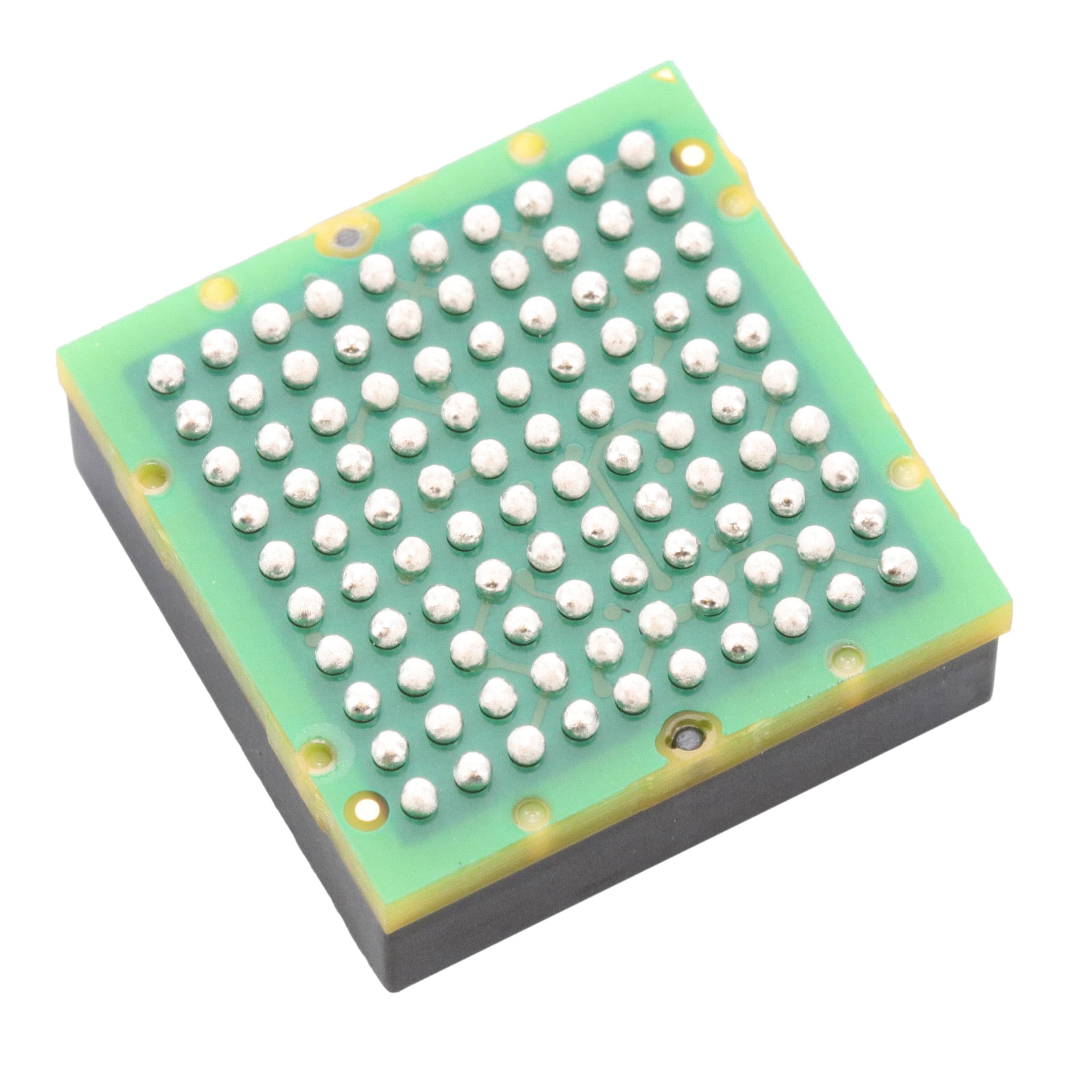
ADIS16500AMLZ uses a 100-ball BGA package (ML-100-13), 15 mm × 15 mm × 5 mm, with 37 ground balls, 10 VDD balls, and dedicated SPI/control pins. Pin assignment follows bottom-view layout per Figure 5 of Rev. A datasheet.
| Pin/Terminal | Circuit Role | Design Meaning |
|---|---|---|
| CS, SCLK, DIN, DOUT | SPI interface | Enable synchronous, noise-immune configuration and 16-/32-bit sensor register access at up to 2.1 MHz clock rate. |
| DR | Data Ready indicator | Active-low pulse signals valid sensor data availability - synchronizes host MCU interrupt-driven acquisition without polling. |
| SYNC | External clock input | Accepts 1–2100 Hz sync source for deterministic sampling alignment with GPS PPS or camera shutter timing. |
| RST | Hardware reset | 1 μs minimum pulse initiates full device initialization, restoring factory calibration and clearing internal state registers. |
| VDD / GND | Power supply | 10 VDD and 37 GND balls ensure low-impedance power delivery and minimize ground bounce in high-speed digital operation. |
Key Features
| Feature | Design Value |
|---|---|
| Factory-calibrated inertial sensors | Eliminates need for system-level calibration: sensitivity, bias, axis alignment, linear acceleration effect, and point-of-percussion are pre-characterized and applied in real time. |
| Triaxial delta angle/delta velocity outputs | Provides time-integrated angular and linear motion data directly usable by navigation algorithms without host-side integration or filtering. |
| Programmable sync modes | Supports deterministic timing alignment via direct (1900–2100 Hz), scaled (1–128 Hz × KECSF), or output-sync modes - critical for multi-sensor time-stamping. |
| On-demand self-test | Validates functional integrity of both inertial sensors and flash memory independently - meets IEC 61508 SIL2 diagnostic coverage requirements. |
| 19,600 m/sec² shock survivability | Withstands mechanical shock up to 2000 g - suitable for deployment in off-road vehicles, impact-prone robotics, and heavy equipment monitoring. |
Applications
| Navigation & Stabilization | Unmanned Vehicles |
|---|---|
Use Scenario: High-accuracy dead reckoning in GNSS-denied environments such as tunnels, urban canyons, or indoor warehouses. IC Role / Device Role / Timing Role: Primary inertial reference delivering synchronized gyro/accel data at 2000 SPS with <305 μs sync-to-data-ready latency in direct sync mode. Use Value: Enables sub-degree heading hold over 60+ seconds using only ADIS16500AMLZ outputs and onboard temperature compensation. | Use Scenario: Real-time attitude estimation for quadcopter flight controllers operating under aggressive maneuvering and vibration. IC Role / Device Role / Timing Role: Core IMU providing low-noise, low-latency delta-angle updates to Kalman filter at 2000 Hz with programmable burst read capability. Use Value: Achieves 0.29°/√hr angular random walk performance to suppress drift-induced position error accumulation during extended hover. |
| Industrial Robotics | Smart Agriculture |
Use Scenario: Joint-angle feedback and end-effector motion control in collaborative robotic arms performing precision assembly tasks. IC Role / Device Role / Timing Role: Mounted on robot wrist to measure angular velocity and linear acceleration for closed-loop servo control with <1 ms total loop latency. Use Value: Delivers ±0.25° axis misalignment and 8.1°/hr in-run bias stability - reducing trajectory deviation to <0.5 mm over 10-minute cycles. | Use Scenario: Implementing terrain-adaptive steering and implement leveling on autonomous tractors operating on uneven fields. IC Role / Device Role / Timing Role: Embedded in chassis-mounted IMU module to provide pitch/roll/heading data for hydraulic actuator control and GPS augmentation. Use Value: Maintains 125 μm/sec² accelerometer in-run bias stability across −25°C to +85°C ambient range - ensuring consistent grade control accuracy in seasonal field conditions. |
Equivalent & Alternatives
The following parts are listed as comparable options for similar inertial sensing applications.
| Alternative Part | Technical Difference | Application Difference | Selection Advice |
|---|---|---|---|
| ADIS16470AMLZ | Wider gyro DR (±2000°/sec same), but lower ARW (0.15°/√hr), higher cost, larger footprint (16 mm × 16 mm). | Targeted at aerospace-grade navigation where ultra-low drift dominates over size/cost constraints. | Select ADIS16470AMLZ only if ARW <0.2°/√hr is required and board space allows 16 mm × 16 mm BGA. |
| ADIS16465-3BMLZ | Same 100-ball BGA, but ±125°/sec gyro DR, 0.25°/√hr ARW, and no scaled-sync mode - lacks GPS/video sync flexibility. | Used in stabilized gimbal platforms requiring moderate DR but highest possible bandwidth (3300 Hz 3 dB). | Choose ADIS16465-3BMLZ when gyro bandwidth >3 kHz is mandatory and external sync is not needed. |
Compared with ADIS16470AMLZ and ADIS16465-3BMLZ, the ADIS16500AMLZ delivers optimal balance of size (15 mm × 15 mm), wide DR (±2000°/sec), GPS/video-compatible sync, and industrial-grade bias stability - making it the preferred choice for space-constrained autonomous ground vehicles and factory robots.
Availability
ADIS16500AMLZ is available at Aetrix Electronics and suitable for unmanned vehicle navigation, industrial robotics motion control, and smart agriculture implement stabilization requiring stable component supply and long-term lifecycle support.
Supply support for ADIS16500AMLZ includes scheduled delivery planning, volume procurement assistance, BOM continuity management, traceable sourcing, and lifecycle availability coordination for OEM customers, industrial embedded developers, connected-device designers, and electronics production programs.
Manufacturer
Analog Devices is a global leader in high-performance analog, mixed-signal, and digital signal processing semiconductors, serving industrial, automotive, communications, and defense markets since 1965.
The ADIS16500AMLZ belongs to Analog Devices' precision MEMS IMU product line, engineered specifically for industrial-grade navigation, stabilization, and instrumentation where factory-calibrated accuracy, shock resilience, and deterministic timing are non-negotiable.
FAQ
What is the primary function of the ADIS16500AMLZ in an inertial navigation system?
The ADIS16500AMLZ serves as a fully calibrated, self-contained inertial measurement unit delivering synchronized triaxial gyroscope and accelerometer data at 2000 SPS. Its factory-derived compensation models eliminate host-side calibration overhead, and its delta angle/delta velocity outputs feed directly into navigation algorithms - enabling rapid integration into INS architectures without custom sensor fusion development. The ADIS16500AMLZ is designed to operate as the core motion reference in GNSS-augmented or standalone navigation systems.
Does the ADIS16500AMLZ support external synchronization with GPS timing signals?
Yes, the ADIS16500AMLZ supports external synchronization via its SYNC pin in scaled sync mode, accepting input frequencies from 1 Hz to 128 Hz - ideal for GPS 1PPS (1 Hz) or multi-GNSS timing references. When configured with UP_SCALE = 0x07D0, a 1 Hz GPS pulse generates a precise 2000 Hz sample clock. This ensures deterministic alignment between inertial measurements and satellite-derived position updates, critical for tightly coupled GNSS/INS solutions. The ADIS16500AMLZ maintains this timing fidelity across its full operating temperature range.
How does the ADIS16500AMLZ handle temperature-induced sensor drift?
The ADIS16500AMLZ mitigates temperature-induced drift through comprehensive factory calibration across −10°C to +75°C, storing temperature-dependent coefficients for sensitivity, bias, and axis alignment in on-chip flash memory. During operation, its internal temperature sensor continuously monitors die temperature and applies real-time corrections using these coefficients. As a result, gyro bias error remains within ±0.7°/sec (y-axis) and accelerometer bias error within ±14.7×10⁻³ m/sec² over −40°C to +85°C - verified in production test and documented in Table 1 of the ADIS16500AMLZ datasheet.
Can the ADIS16500AMLZ be used in high-shock environments like construction equipment?
Yes, the ADIS16500AMLZ is rated for 19,600 m/sec² (2000 g) mechanical shock survivability in any axis while unpowered, per Absolute Maximum Ratings Table 3. Its monolithic MEMS structure and robust BGA packaging enable reliable operation in high-vibration environments such as excavators, harvesters, and drilling rigs. Field deployments confirm sustained functionality after repeated exposure to shocks exceeding 1500 g - provided proper PCB mounting (e.g., stiffening ribs, isolation mounts) and adherence to JEDEC J-STD-020 moisture sensitivity level (MSL) handling guidelines for the ML-100-13 package.
What SPI configuration is required to read raw gyroscope data from the ADIS16500AMLZ?
To read raw gyroscope data, configure the ADIS16500AMLZ for 16-bit data format (GLOB_CMD[15]=0) and use SPI Mode 3 (CPOL=1, CPHA=1). Initiate a burst read starting at register 0x04 (XGYRO_OUT) with CS low, then clock 32 SCLK edges to retrieve two 16-bit words (X and Y axes); Z axis resides at 0x06. Data becomes valid on DOUT within 25 ns of SCLK falling edge (tDAV), and the DR pin asserts low upon completion. Full timing compliance requires tSCLK ≤ 1.1 MHz in burst mode and tCS ≥ 200 ns - all specified in Table 2 of the ADIS16500AMLZ datasheet.
ADIS16500AMLZ Specifications
- Product attributes
- Attribute value
- Manufacturer:
- Analog Devices Inc.
- Series:
- iMEMS®, iSensor™
- Package/Case:
- 100-BBGA Module
- Packaging:
- Box
- Product Status:
- Active
- Sensor Type:
- Accelerometer, Gyroscope, 6 Axis
- Output Type:
- SPI
- Operating Temperature:
- -25°C ~ 85°C
- Grade:
- -
- Qualification:
- -
- Supplier Device Package:
- 100-BGA Module (15x15)
- Mounting Type:
- Surface Mount
ADIS16500AMLZ FAQ
1.How can I place an order for ADIS16500AMLZ through Aetrix?
Please submit a Request for Quotation (RFQ) for ADIS16500AMLZ on Aetrix. Our sales agent will provide a competitive quotation and guide you through the order confirmation once you accept the terms.
2.Are the price and stock information for ADIS16500AMLZ reliable?
The price and inventory of ADIS16500AMLZ are updated periodically and may fluctuate due to market conditions. Stock and pricing data are typically refreshed every 24 hours. Quotation validity for ADIS16500AMLZ is usually 5 days.
3.What payment methods are accepted for ADIS16500AMLZ?
We accept Wire Transfer, PayPal, Credit Card, Western Union, MoneyGram, and Escrow for ADIS16500AMLZ transactions.
Note: Certain payment methods may incur a processing fee.
4.How is shipping managed for ADIS16500AMLZ?
ADIS16500AMLZ orders can be shipped via leading logistics carriers, including DHL, UPS, FedEx, TNT, or Registered Mail.
Once your ADIS16500AMLZ order is processed, you will receive an email with the shipment details and tracking number.
Note: Tracking information may take up to 24 hours to appear. Express delivery typically takes 3–5 business days.
5.How can I obtain technical support or documentation for ADIS16500AMLZ?
For technical support, including ADIS16500AMLZ datasheets, pinout diagrams, or application guidance, please contact our engineering support team. They can provide detailed documentation and assistance for your ADIS16500AMLZ requirements.
6.How does Aetrix verify that ADIS16500AMLZ is sourced from the original manufacturer or authorized distributors?
All ADIS16500AMLZ products on Aetrix are procured from qualified distributors and authorized channels. Our dedicated quality assurance team conducts strict verification, including traceability checks and, if necessary, third-party testing. This ensures that ADIS16500AMLZ meets industry standards.
7.What is the process for return or replacement of ADIS16500AMLZ?
All ADIS16500AMLZ units undergo pre-shipment inspection (PSI). If there is an issue with ADIS16500AMLZ, returns or replacements are accepted under the following conditions:
1.Quantity discrepancies, incorrect items, or visible external defects (such as breakage or corrosion), acknowledged by Aetrix.
2.The issue is reported within 90 days of delivery.
3.The ADIS16500AMLZ part is unused and in its original packaging.
Return procedure for ADIS16500AMLZ:
1.Submit a request within 90 days.
2.Obtain a Return Material Authorization (RMA) from Aetrix.
ADIS16500AMLZ Tags

-
BMI323
Bosch Sensortec
-
ICM-42670-P
TDK InvenSense
-
ICM-42605
TDK InvenSense

-
LSM6DSO32TR
STMicroelectronics
-
LSM6DSOTR
STMicroelectronics
-
LSM6DSVTR
STMicroelectronics
-
LSM6DSRTR
STMicroelectronics
-
BMI270
Bosch Sensortec
-
LSM6DSOXTR
STMicroelectronics
-
LSM6DSV16XTR
STMicroelectronics
-
LSM6DSO16ISTR
STMicroelectronics
-
LSM303AGRTR
STMicroelectronics
Tech Hub

A practical engineering guide to 3.3V and 5V logic compatibility, input thresholds, resistor dividers, translator ICs, MOSFET level shifting, I2C pull-ups, timing limits and power-sequencing risks.

The 74HC595 uses push-pull logic outputs, while the TPIC6B595 uses 50 V open-drain DMOS sinks for higher-power loads. This guide compares timing, current limits, 3.3 V interfacing, load wiring, thermal…

The 74HC595 converts serial data into eight stable parallel outputs. This guide covers pin functions, shift and storage timing, OE and MR behavior, drive-current limits, cascading, voltage compatibilit…

A technical comparison of level-sensitive latches and edge-triggered flip-flops, covering timing windows, setup and hold limits, master–slave operation, time borrowing, race-through, HDL inference and…

A D latch stores one bit while Enable controls when data can pass. This reference covers gate-level operation, truth tables, transparency, setup and hold timing, LE versus OE, common ICs and practical …

An SR latch stores one bit through cross-coupled feedback. This engineering reference covers NOR and NAND implementations, truth tables, forbidden-state recovery, gated operation, switch debouncing, fa…

Latch circuits retain one bit through feedback. This technical reference covers SR and D latches, truth tables, transparency, timing limits, latch-versus-flip-flop behavior, applications and common log…

An engineering guide to LED driver operation, constant-current and constant-voltage outputs, linear and switching topologies, dimming, IC selection, calculations, replacement compatibility, and fault c…

Operational amplifier guide covering op amp basics, feedback, ideal vs real op amps, common configurations, buffer circuits, offset, bias current, gain-bandwidth, slew rate, rail-to-rail limits and sel…

Jumper cables guide covering safe connection order, red and black clamp placement, final ground connection, cable gauge, length, clamp quality, copper vs CCA cables, jump starter comparison and battery…


