
 My Inquiry
 My Account


Microchip Technology AT73C202
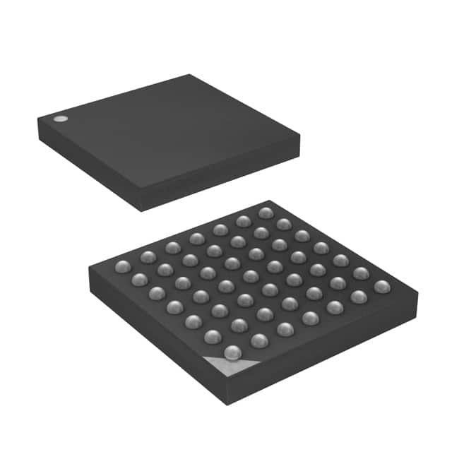
- Part No.:
- AT73C202
- Manufacturer:
- Microchip Technology
- Category:
- Power Management - Specialized
- Package:
- 49-VFBGA
- Datasheet:
-
 AT73C202.pdf
- Description:
- IC PWR/BATT MGMT FOR CELL 49FBGA
- Quantity:
- Payment:

- Shipping:

Inventory:3,367
Please send an inquiry. Send us your inquiry, and we will respond immediately.
Product details
Overview
AT73C202 from Atmel is a power and battery management IC designed for 2.5G GSM cellular phones, integrating a 300mA/1.8V–2.5V DC-DC converter, seven LDOs (including dual 130mA/2.8V RF LDOs, 130mA/2.7V–2.8V analog LDO, 80mA/2.8V I/O PAD LDO, 10mA SIM LDO, 2mA backup battery LDO, and 0.5mA RTC LDO), Li-ion/Li-polymer charger controller, vibrator/buzzer drivers, SIM level shifters, and ultra-low sleep mode current (17 µA typ). It serves as the central power subsystem for baseband, RF, analog, memory, and peripheral blocks in mobile handsets.
For engineers reviewing the AT73C202 datasheet, AT73C202 pinout, AT73C202 application, or AT73C202 equivalent, this page delivers verified specifications including DC-DC output voltage accuracy (±50 mV static load regulation), RF LDO PSRR (70–73 dB at 217 Hz), V-CORE efficiency (90% at 10–200 mA), RTC LDO quiescent current (4.8–9.7 µA), and FBGA-49 package mechanical data - all critical for GSM phone power architecture validation and BOM selection.
Technical Context
The AT73C202 implements a hardwired power management state machine that autonomously handles wake-up/shut-down sequencing, charger plug-in/out detection (via DC-ON), battery pre-charge (50 mA pulsed), and safe start-up under low-battery or thermal fault conditions. Its DC-DC converter supports both PWM mode (1.8V/2.5V outputs) and LDO mode (1.75–2.45V) selectable via BB1 and ECO-MODE pins, enabling dynamic core voltage scaling during transmission bursts.
Seven dedicated LDOs are partitioned by function: dual high-PSRR RF LDOs (70–73 dB) with 29–37 µVRMS noise for sensitive transceiver biasing; an analog LDO (2.7–2.85V, 130 mA) with 70 dB PSRR; a 2.8V/80mA digital PAD LDO; a 1.5V/0.5mA ultra-low-power RTC LDO; a 2.4–2.75V/5mA backup battery LDO; and a 1.8V/2.8V/10mA SIM LDO with integrated level shifting - all sharing independent enable controls and ground domains.
Key Specifications
| Parameter | Value and Actual Design Meaning |
|---|---|
| DC-DC Output | 1.8V or 2.5V @ 300 mA (PWM mode); ±50 mV static load regulation ensures stable baseband core supply during burst-mode operation |
| RF LDO PSRR | 70–73 dB at 217 Hz - suppresses baseband switching noise coupling into RF front-end, critical for GSM TX spectral mask compliance |
| Sleep Mode Current | 17 µA typ (MODE2/MODE3) - enables multi-day standby on single-cell Li-ion battery without compromising RTC functionality |
| RTC LDO Quiescent Current | 4.8–9.7 µA - sustains real-time clock operation during deep sleep while minimizing backup battery drain |
| Charger Pre-charge Current | 50 mA pulsed - safely conditions deeply discharged batteries (<3.2V) before fast charge initiation, preventing thermal runaway |
| Package | 49-ball FBGA, 5 mm × 5 mm, 0.65 mm pitch - compact footprint compatible with space-constrained mobile phone PCB layouts |
| Operating Temperature | −40°C to +85°C - qualified for industrial-grade mobile handset deployment across global environmental conditions |
Pinout & Package
The AT73C202 is housed in a 49-ball FBGA package (7×7 matrix, 0.65 mm pitch, 5 mm × 5 mm outline) with dedicated ground balls (AA-GND, A-GND, D-GND, GND-REG1, GND-RF) and functionally isolated power domains for RF, analog, digital, and charger sections.
| Pin/Terminal | Circuit Role | Design Meaning |
|---|---|---|
| V-CORE | DC-DC Output | Delivers regulated 1.8V/2.5V to baseband processor core; requires external 10 µH inductor and 22 µF tantalum capacitor |
| A-VCC | Analog LDO Output | Supplies 2.7–2.85V @ 130 mA to baseband analog section; 70 dB PSRR rejects switching noise from DC-DC |
| V-RF1 / V-RF2 | RF LDO Outputs | Provide 2.8V @ 130 mA each to RF transceiver blocks; 29–37 µVRMS noise meets GSM receiver sensitivity requirements |
| V-RTC | RTC LDO Output | Generates 1.5V @ 0.5 mA for real-time clock during sleep; 4.8–9.7 µA IQ enables >1-year backup battery life |
| BAT-VOLT | Battery Voltage Sense | Resistance divider output for baseband MCU to monitor battery voltage during charging phases |
| CHG-IN | Charger Adapter Input | Accepts 4.6–5.5V AC/DC adapter input; triggers DC-ON high to initiate power-on sequence |
| RES-B | Reset Open Collector | Active-low reset signal asserted when thermal fault or watchdog timeout occurs; requires external pull-up |
Key Features
| Feature | Design Value |
|---|---|
| Integrated Charger Controller | Hardware-managed pre-charge (50 mA), fast charge, and pulse charge phases - eliminates need for external charge management IC and reduces firmware complexity |
| Dual High-PSRR RF LDOs | 70–73 dB ripple rejection at 217 Hz - maintains RF transceiver linearity and adjacent channel power ratio (ACPR) under noisy DC-DC switching conditions |
| Ultra-Low Sleep Current | 17 µA typical system sleep current - extends standby time in GSM handsets without sacrificing RTC or SIM retention |
| Hardwired Power State Machine | Autonomous sequencing for ON/OFF key press, charger plug-in, battery insertion, and low-voltage recovery - ensures robust boot reliability without baseband intervention |
| Independent LDO Enables | EN-RF1, EN-RF2, EN-ANA-B, EN-VIB pins allow dynamic power gating of RF, analog, and vibrator blocks - enables precise power budgeting per operational mode |
Applications
| GSM Baseband Power Subsystem | RF Transceiver Bias Supply |
|---|---|
Use Scenario: Powering the digital signal processor (DSP), microcontroller, and memory subsystems in a 2.5G GSM handset during active call and idle modes. IC Role / Device Role / Timing Role: Central power management unit delivering regulated V-CORE (1.8V/2.5V), V-PAD (2.8V), and A-VCC (2.7–2.85V) with dynamic mode switching between PWM and LDO. Use Value: 90% DC-DC efficiency at 10–200 mA load and 17 µA sleep current directly extend talk time and standby duration beyond industry benchmarks. | Use Scenario: Providing clean, low-noise bias to GSM RF power amplifier and receiver chain in dual-band handsets. IC Role / Device Role / Timing Role: Dual 130mA/2.8V RF LDOs (V-RF1/V-RF2) with 70–73 dB PSRR and 29–37 µVRMS output noise. Use Value: Maintains GSM TX spectral mask compliance and RX sensitivity by rejecting 217 Hz baseband switching ripple that would otherwise degrade EVM and BER. |
| Real-Time Clock Backup System | SIM Card Interface Management |
Use Scenario: Sustaining accurate timekeeping and alarm functions during full system shutdown or battery removal in GSM handsets. IC Role / Device Role / Timing Role: Ultra-low-power RTC LDO (V-RTC) delivering 1.5V @ 0.5 mA with 4.8–9.7 µA quiescent current from backup battery. Use Value: Enables >1-year RTC operation on CR2032 coin cell while maintaining 1.5V ±50 mV regulation across temperature and aging. | Use Scenario: Powering and level-shifting signals for 1.8V/2.8V SIM cards in dual-voltage mobile handsets. IC Role / Device Role / Timing Role: Integrated SIM LDO (10 mA) with programmable output (SIM-1V8/2V8) and dedicated SIM-RST/SIM-CLK/SIM-IO drivers. Use Value: Eliminates discrete level shifters and reduces SIM interface BOM count by 4 components while supporting hot-swap and 5 MHz clock rates. |
Equivalent & Alternatives
The following parts are listed as comparable options for similar power management applications.
| Alternative Part | Technical Difference | Application Difference | Selection Advice |
|---|---|---|---|
| MAX1586B | Single 600mA DC-DC + 3x LDOs; no integrated SIM interface or vibrator driver; 24-pin TQFN vs. 49-ball FBGA | Targeted at general-purpose handhelds, not GSM-specific RF noise requirements | Choose MAX1586B only if RF PSRR >70 dB and SIM level shifting are not required |
| TPS65561 | 3x DC-DC + 5x LDOs; higher integration but no hardware charger state machine; 48-pin QFN vs. FBGA | Designed for multimedia smartphones, lacks GSM-optimized sleep current and battery pre-charge logic | Prefer TPS65561 for feature-rich UI platforms where 17 µA sleep current is secondary to multi-rail flexibility |
Compared with MAX1586B and TPS65561, the AT73C202 uniquely combines GSM-specific features - including dual high-PSRR RF LDOs, hardware-enforced battery pre-charge, SIM level shifting, and 17 µA sleep current - within a compact FBGA package optimized for 2.5G handset form factors.
Availability
AT73C202 is available at Aetrix Electronics and suitable for GSM handset design, cellular baseband power subsystems, and RF transceiver bias applications requiring stable component supply, long-term lifecycle support, and automotive-qualified thermal performance.
Supply support for AT73C202 includes scheduled delivery planning, volume procurement assistance, BOM continuity management, traceable sourcing, and lifecycle availability coordination for OEM customers, industrial embedded developers, connected-device designers, and electronics production programs.
Manufacturer
Atmel Corporation (now part of Microchip Technology) is a semiconductor manufacturer specializing in microcontrollers, nonvolatile memory, and power management ICs for embedded and mobile applications.
The AT73C202 belongs to Atmel's Power Management for Mobiles (PM) product line, engineered specifically to consolidate power, battery charging, RF/analog/digital rail generation, and SIM interface functions into a single IC for cost-sensitive 2.5G GSM handsets.
FAQ
What is the primary application domain for the AT73C202?
The AT73C202 is purpose-built for 2.5G GSM cellular handsets, serving as the central power management unit that integrates DC-DC conversion, seven LDOs (for RF, analog, digital, RTC, SIM, and backup battery), Li-ion charging control, vibrator/buzzer drivers, and SIM interface level shifting. Its design targets space-constrained, battery-operated mobile phones requiring ultra-low sleep current (17 µA typ) and GSM-specific noise immunity.
Does the AT73C202 support both 1.8V and 2.8V SIM card voltages?
Yes, the AT73C202 includes a dedicated SIM LDO with programmable output voltage. The SIM-1V8/2V8 pin selects between 1.8V (when driven high) and 2.8V (when driven low), and the SIM-VCC output delivers up to 10 mA at the selected voltage. This eliminates external level shifters and supports hot-swappable SIM cards in dual-voltage GSM handsets.
How does the AT73C202 manage battery charging safety?
The AT73C202 implements hardware-enforced charging safety: pre-charge limits current to 50 mA for batteries below 3.2V; fast/pulse charge is software-controlled via the CHG pin; and thermal protection disables charging if junction temperature exceeds 120°C. Battery voltage monitoring via BAT-VOLT and external temperature sensing ensure compliance with Li-ion charge profiles without relying solely on baseband firmware.
What is the significance of the 70–73 dB PSRR specification for the AT73C202's RF LDOs?
The 70–73 dB PSRR at 217 Hz means the AT73C202's V-RF1 and V-RF2 LDOs attenuate baseband switching noise by over 1,000×. This is critical for GSM transceivers, where 217 Hz ripple from the DC-DC converter could otherwise degrade transmitter spectral purity (ACPR) and receiver sensitivity (BER), causing failed conformance testing.
Can the AT73C202 operate with a dead or deeply discharged battery?
Yes - the AT73C202 initiates autonomous pre-charge when VBAT < 3.2V, delivering pulsed 50 mA current to recover the battery before enabling full system power. Its power-on controller validates battery voltage (>3.2V), thermal status (<120°C), and charger presence before asserting V-CORE, ensuring safe startup even after complete discharge or cold-temperature storage.
AT73C202 Specifications
- Product attributes
- Attribute value
- Manufacturer:
- Microchip Technology
- Series:
- -
- Package/Case:
- 49-VFBGA
- Packaging:
- Tape & Reel (TR)
- Product Status:
- Obsolete
- Applications:
- Cell Phone
- Current - Supply:
- -
- Voltage - Supply:
- 3V ~ 5.5V
- Operating Temperature:
- -40°C ~ 85°C
- Grade:
- -
- Qualification:
- -
- Mounting Type:
- Surface Mount
- Supplier Device Package:
- 49-VFBGA (5x5)
AT73C202 FAQ
1.How can I place an order for AT73C202 through Aetrix?
Please submit a Request for Quotation (RFQ) for AT73C202 on Aetrix. Our sales agent will provide a competitive quotation and guide you through the order confirmation once you accept the terms.
2.Are the price and stock information for AT73C202 reliable?
The price and inventory of AT73C202 are updated periodically and may fluctuate due to market conditions. Stock and pricing data are typically refreshed every 24 hours. Quotation validity for AT73C202 is usually 5 days.
3.What payment methods are accepted for AT73C202?
We accept Wire Transfer, PayPal, Credit Card, Western Union, MoneyGram, and Escrow for AT73C202 transactions.
Note: Certain payment methods may incur a processing fee.
4.How is shipping managed for AT73C202?
AT73C202 orders can be shipped via leading logistics carriers, including DHL, UPS, FedEx, TNT, or Registered Mail.
Once your AT73C202 order is processed, you will receive an email with the shipment details and tracking number.
Note: Tracking information may take up to 24 hours to appear. Express delivery typically takes 3–5 business days.
5.How can I obtain technical support or documentation for AT73C202?
For technical support, including AT73C202 datasheets, pinout diagrams, or application guidance, please contact our engineering support team. They can provide detailed documentation and assistance for your AT73C202 requirements.
6.How does Aetrix verify that AT73C202 is sourced from the original manufacturer or authorized distributors?
All AT73C202 products on Aetrix are procured from qualified distributors and authorized channels. Our dedicated quality assurance team conducts strict verification, including traceability checks and, if necessary, third-party testing. This ensures that AT73C202 meets industry standards.
7.What is the process for return or replacement of AT73C202?
All AT73C202 units undergo pre-shipment inspection (PSI). If there is an issue with AT73C202, returns or replacements are accepted under the following conditions:
1.Quantity discrepancies, incorrect items, or visible external defects (such as breakage or corrosion), acknowledged by Aetrix.
2.The issue is reported within 90 days of delivery.
3.The AT73C202 part is unused and in its original packaging.
Return procedure for AT73C202:
1.Submit a request within 90 days.
2.Obtain a Return Material Authorization (RMA) from Aetrix.
AT73C202 Tags

-
TPS2511DGNR
Texas Instruments

-
UTC2000/MG
Microchip Technology

-
TUSB320HAIRWBR
Texas Instruments

-
TPS61252DSGR
Texas Instruments

-
PI5USB30216CXUAEX
Diodes Incorporated

-
SN6501DBVR
Texas Instruments

-
CYPD3177-24LQXQT
Infineon Technologies
-
SN6501QDBVRQ1
Texas Instruments

-
STUSB1600AQTR
STMicroelectronics

-
SN6505BDBVR
Texas Instruments
-
SN6501DBVT
Texas Instruments

-
TPS65150PWPR
Texas Instruments
Tech Hub

TTL and CMOS logic families differ in thresholds, loading, output drive, power and timing. This engineering guide compares 74HC and 74HCT, calculates noise margins and checks 3.3 V/5 V compatibility.

A practical engineering guide to 3.3V and 5V logic compatibility, input thresholds, resistor dividers, translator ICs, MOSFET level shifting, I2C pull-ups, timing limits and power-sequencing risks.

The 74HC595 uses push-pull logic outputs, while the TPIC6B595 uses 50 V open-drain DMOS sinks for higher-power loads. This guide compares timing, current limits, 3.3 V interfacing, load wiring, thermal…

The 74HC595 converts serial data into eight stable parallel outputs. This guide covers pin functions, shift and storage timing, OE and MR behavior, drive-current limits, cascading, voltage compatibilit…

A technical comparison of level-sensitive latches and edge-triggered flip-flops, covering timing windows, setup and hold limits, master–slave operation, time borrowing, race-through, HDL inference and…

A D latch stores one bit while Enable controls when data can pass. This reference covers gate-level operation, truth tables, transparency, setup and hold timing, LE versus OE, common ICs and practical …

An SR latch stores one bit through cross-coupled feedback. This engineering reference covers NOR and NAND implementations, truth tables, forbidden-state recovery, gated operation, switch debouncing, fa…

Latch circuits retain one bit through feedback. This technical reference covers SR and D latches, truth tables, transparency, timing limits, latch-versus-flip-flop behavior, applications and common log…

An engineering guide to LED driver operation, constant-current and constant-voltage outputs, linear and switching topologies, dimming, IC selection, calculations, replacement compatibility, and fault c…

Operational amplifier guide covering op amp basics, feedback, ideal vs real op amps, common configurations, buffer circuits, offset, bias current, gain-bandwidth, slew rate, rail-to-rail limits and sel…


