
 My Inquiry
 My Account


Diodes Incorporated DPO2036DBB-7
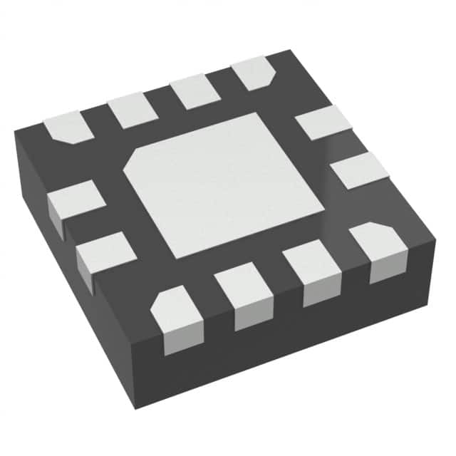
- Part No.:
- DPO2036DBB-7
- Manufacturer:
- Diodes Incorporated
- Category:
- Surge Suppression Ics
- Package:
- 12-UFQFN Exposed Pad
- Datasheet:
-
 DPO2036DBB-7.pdf
- Description:
- DATALINE OVER VOLTAGE PROTECTION
- Quantity:
- Payment:

- Shipping:

Inventory:43,881
Please send an inquiry. Send us your inquiry, and we will respond immediately.
Product details
Overview
DPO2036DBB-7 from Diodes Incorporated is a 4-channel USB Type-C® over-voltage protection IC designed to safeguard CC1/CC2 and SBU1/SBU2 signal paths against short-to-VBUS faults. It integrates dual-pair OVP FETs with RDS(ON) of 350 mΩ (CC) and 5 Ω (SBU), auto-recovery response ≤100 ns, and dead-battery pull-down resistors (5.1 kΩ typ.) for CC lines-enabling power negotiation in fully depleted mobile systems.
For engineers reviewing the DPO2036DBB-7 datasheet, DPO2036DBB-7 pinout, DPO2036DBB-7 application, or DPO2036DBB-7 equivalent, key selection criteria include VOVP thresholds (6.0 V CC / 4.5 V SBU), ±22 V short-to-VBUS tolerance, 200 MHz CC bandwidth, thermal shutdown at +150°C, and U-QFN2020-12 (Type B) package compatibility with high-density USB-C port layouts.
Technical Context
The DPO2036DBB-7 implements four independent uni-directional OVP switches-two for CC pins (CC1C/CC2C → CC1S/CC2S) and two for SBU pins (SBU1C/SBU2C → SBU1S/SBU2S)-each with dedicated voltage comparators, hysteresis (140 mV CC / 110 mV SBU), and fast turn-off logic. Fault detection triggers FAULTB assertion within 300 μs and isolates system-side I/O within 100 ns.
It supports dual-power sourcing: primary operation from VVSYS (2.7–5.5 V), with seamless fallback to VCONN-derived power during dead-battery mode via integrated RD pull-downs on CC1C/CC2C. Thermal shutdown (+150°C) and UVLO (2.4 V) ensure robustness under abnormal supply or ambient conditions.
Key Specifications
| Parameter | Value and Actual Design Meaning |
|---|---|
| OVP Threshold (CC) | 6.0 V typical - triggers isolation before VBUS-induced EOS damages sub-micron USB PD controllers |
| OVP Threshold (SBU) | 4.5 V typical - protects low-voltage SBU analog signaling paths from 5 V/9 V/15 V VBUS shorts |
| RDS(ON) (CC path) | 350 mΩ typical - minimizes voltage drop and signal distortion on high-speed CC configuration channel |
| RDS(ON) (SBU path) | 5 Ω typical - balances low-leakage isolation with acceptable insertion loss for auxiliary analog signals |
| Response Time | <100 ns - ensures system-side ICs survive transient VBUS shorts without latch-up or gate oxide rupture |
| Bandwidth (CC) | 200 MHz - preserves USB PD communication integrity up to 300 kbps BMC signaling |
| Dead-Battery RD | 5.1 kΩ typical - meets USB Type-C Specification pull-down requirement for source detection when battery = 0 V |
Pinout & Package
Housed in a 2.0 mm × 2.0 mm × 0.5 mm U-QFN2020-12 (Type B) package with exposed thermal pad, the DPO2036DBB-7 uses a 3×4 pin grid with pin 1 marked by top-side dot. The thermal pad must be soldered to PCB ground plane for thermal management (RθJA = 96°C/W).
| Pin/Terminal | Circuit Role | Design Meaning |
|---|---|---|
| 1 SBU1C | USB-C connector side SBU1 input | Receives SBU1 signal from Type-C receptacle; rated for 24 V max short-to-VBUS |
| 2 SBU2C | USB-C connector side SBU2 input | Receives SBU2 signal; enables dual-auxiliary channel protection |
| 3 CC1C | USB-C connector side CC1 input | Primary configuration channel input; includes embedded 5.1 kΩ pull-down for dead-battery mode |
| 4 CC2C | USB-C connector side CC2 input | Redundant configuration channel input; identical dead-battery support as CC1C |
| 5 CB | ESD capacitor connection | Requires 0.1 μF capacitor to GND to suppress ESD transients on all protected lines |
| 6 FAULTB | Active-low fault indicator | Open-drain output asserted low during OVP; sinks ≤8 mA; requires external pull-up |
| 7 CC2S | System-side CC2 output | Drives CC2 pin of USB PD controller or mux; isolated during OVP |
| 8 CC1S | System-side CC1 output | Drives CC1 pin of host IC; maintains signal integrity with 50 pF CIN |
| 9 SBU2S | System-side SBU2 output | Routes SBU2 to baseband processor or audio codec; 5 pF CIN preserves analog fidelity |
| 10 SBU1S | System-side SBU1 output | Delivers SBU1 signal to system IC; supports crosstalk <−80 dB at 1 MHz |
| 11 GND | Power and signal reference | Common return for all channels and thermal pad; must connect to solid ground plane |
| 12 VSYS | Main supply input | Accepts 2.7–5.5 V system rail; powers internal logic, comparators, and FET drivers |
Key Features
| Feature | Design Value |
|---|---|
| Auto-recovery OVP | CC/SBU channels restore conduction after fault removal in 26–38 ms (fast recovery) or 1 ms (post-long-fault), eliminating manual reset |
| Dead-battery CC support | Integrated 5.1 kΩ pull-downs on CC1C/CC2C activate automatically when VVSYS < UVLO, enabling charging negotiation with zero battery voltage |
| Short-to-VBUS tolerance | Withstands 22 V on CC/SBU connector pins without damage-exceeding USB PD 3.0 VBUS max (20 V) |
| Thermal protection | Shuts down at +150°C junction temperature with +20°C hysteresis, preventing thermal runaway during sustained overload |
| IEC61000-4-2 ESD rating | ±2.0 kV HBM on all protected pins (CC1C/CC2C/SBU1C/SBU2C), eliminating need for external TVS diodes |
Applications
| USB-C Mobile Phone Charging Port | USB-C Docking Station Hub |
|---|---|
|
Use Scenario: Protects smartphone SoC USB PD controller during hot-plug into high-power chargers or damaged cables causing CC/SBU-to-VBUS shorts. IC Role / Device Role / Timing Role: Acts as fail-safe series switch between USB-C receptacle and application processor's USB PD PHY; asserts FAULTB within 300 μs. Use Value: Prevents irreversible gate oxide failure in 28 nm/16 nm PD controllers by limiting fault energy via 100 ns OVP response and 350 mΩ RDS(ON). |
Use Scenario: Shields multi-port USB-C hub controller from cross-port VBUS coupling or cable assembly defects affecting SBU/CC lines. IC Role / Device Role / Timing Role: Provides per-port OVP for four independent CC/SBU paths; FAULTB signals host MCU to disable affected port. Use Value: Enables hot-swap reliability in 10+ port hubs by isolating faults without disrupting other active data/power lanes. |
| VR/AR Headset USB-C Interface | Thin-and-Light Notebook USB-C Port |
|
Use Scenario: Secures headset's audio/video auxiliary (SBU) and configuration (CC) lines during repeated plugging into PC or charger with varying VBUS levels. IC Role / Device Role / Timing Role: Maintains signal fidelity (200 MHz CC / 600 MHz SBU bandwidth) while blocking >6 V transients on CC and >4.5 V on SBU. Use Value: Eliminates audible pop/noise in analog SBU audio paths and prevents BMC protocol lockup during transient overvoltage events. |
Use Scenario: Integrates into ultra-thin notebook motherboard where space constraints prohibit discrete OVP solutions near USB-C receptacle. IC Role / Device Role / Timing Role: Replaces 4× discrete MOSFETs + comparators + logic in 2.0 mm² footprint; thermal pad enables 1.3 W dissipation. Use Value: Reduces BOM count by 70% and PCB area by 65% versus discrete protection while meeting USB-IF compliance for short-to-VBUS immunity. |
Equivalent & Alternatives
The following parts are listed as comparable options for similar USB-C over-voltage protection applications.
| Alternative Part | Technical Difference | Application Difference | Selection Advice |
|---|---|---|---|
| TUSB546A | Single-channel USB 3.1 re-driver with integrated OVP; no SBU support; 3.3 V only supply | Designed for SuperSpeed data path protection-not CC/SBU signal integrity | Select only if protecting high-speed data lanes (TX/RX), not configuration/auxiliary pins |
| TPD6S300A | 3-channel solution (CC1/CC2/SBU1 only); no SBU2 protection; 5.5 V OVP threshold fixed | Lacks second SBU channel and auto-recovery; requires external reset for fault clearance | Use when SBU2 is unused and system-level fault handling can tolerate manual reset |
Compared with TUSB546A and TPD6S300A, the DPO2036DBB-7 uniquely delivers full 4-channel (CC1/CC2/SBU1/SBU2) protection with auto-recovery, dead-battery support, and dual OVP thresholds-making it the only single-chip solution for complete USB-C receptacle-side signal path hardening.
Availability
DPO2036DBB-7 is available at Aetrix Electronics and suitable for notebook PCs, VR headsets, and universal docking stations requiring stable component supply, USB-IF compliance assurance, and production-grade thermal performance.
Supply support for DPO2036DBB-7 includes scheduled delivery planning, volume procurement assistance, BOM continuity management, traceable sourcing, and lifecycle availability coordination for OEM customers, industrial embedded developers, connected-device designers, and electronics production programs.
Manufacturer
Diodes Incorporated is a global manufacturer of discrete semiconductors and ICs, specializing in power management, signal integrity, and protection solutions for consumer, computing, and industrial markets.
The DPO2036DBB-7 belongs to Diodes' USB-C Protection product line, engineered specifically to address short-to-VBUS failure modes in compact portable devices-prioritizing ultra-fast response, minimal signal degradation, and dead-battery interoperability.
FAQ
What is the maximum VBUS voltage the DPO2036DBB-7 can withstand on CC and SBU pins?
The DPO2036DBB-7 supports short-to-VBUS tolerance up to 22 V on both CCxC and SBUxC pins, verified under hot-plug test conditions with 1-meter USB-C cables and specified load networks. This exceeds the USB PD 3.0 specification's 20 V VBUS maximum and ensures survivability against common cable/connector fault scenarios.
Does the DPO2036DBB-7 require external pull-up resistors on the FAULTB pin?
Yes, FAULTB is an open-drain output and requires an external pull-up resistor (typically 4.7–10 kΩ) to a 2.7–5.5 V rail. The device sinks up to 8 mA when asserting fault; the pull-up value must ensure VOL ≤ 0.4 V under worst-case sink current and PCB trace capacitance.
How does the dead-battery mode function without external components?
The DPO2036DBB-7 embeds precision 5.1 kΩ pull-down resistors on CC1C and CC2C pins, activated automatically when VVSYS falls below 2.4 V UVLO threshold. This satisfies USB Type-C Specification RD requirements, enabling source detection and VCONN-powered charging even with 0 V battery voltage-no external resistors needed.
Can the DPO2036DBB-7 protect both CC and SBU lines simultaneously during a single fault event?
Yes-the device monitors all four inputs (CC1C, CC2C, SBU1C, SBU2C) independently. A fault on any one pin triggers immediate FAULTB assertion and simultaneous turn-off of all four OVP FETs, ensuring complete isolation of system-side CC1S/CC2S/SBU1S/SBU2S from the faulted connector-side path.
DPO2036DBB-7 Specifications
- Product attributes
- Attribute value
- Manufacturer:
- Diodes Incorporated
- Package/Case:
- 12-UFQFN Exposed Pad
- Series:
- -
- Packaging:
- Tape & Reel (TR)
- Product Status:
- Active
- Voltage - Clamping:
- 7V
- Technology:
- Internal Switch
- Number of Circuits:
- 4
- Applications:
- -
- Grade:
- -
- Qualification:
- -
- Mounting Type:
- Surface Mount
- Supplier Device Package:
- U-QFN2020-12 (Type B)
DPO2036DBB-7 FAQ
1.How can I place an order for DPO2036DBB-7 through Aetrix?
Please submit a Request for Quotation (RFQ) for DPO2036DBB-7 on Aetrix. Our sales agent will provide a competitive quotation and guide you through the order confirmation once you accept the terms.
2.Are the price and stock information for DPO2036DBB-7 reliable?
The price and inventory of DPO2036DBB-7 are updated periodically and may fluctuate due to market conditions. Stock and pricing data are typically refreshed every 24 hours. Quotation validity for DPO2036DBB-7 is usually 5 days.
3.What payment methods are accepted for DPO2036DBB-7?
We accept Wire Transfer, PayPal, Credit Card, Western Union, MoneyGram, and Escrow for DPO2036DBB-7 transactions.
Note: Certain payment methods may incur a processing fee.
4.How is shipping managed for DPO2036DBB-7?
DPO2036DBB-7 orders can be shipped via leading logistics carriers, including DHL, UPS, FedEx, TNT, or Registered Mail.
Once your DPO2036DBB-7 order is processed, you will receive an email with the shipment details and tracking number.
Note: Tracking information may take up to 24 hours to appear. Express delivery typically takes 3–5 business days.
5.How can I obtain technical support or documentation for DPO2036DBB-7?
For technical support, including DPO2036DBB-7 datasheets, pinout diagrams, or application guidance, please contact our engineering support team. They can provide detailed documentation and assistance for your DPO2036DBB-7 requirements.
6.How does Aetrix verify that DPO2036DBB-7 is sourced from the original manufacturer or authorized distributors?
All DPO2036DBB-7 products on Aetrix are procured from qualified distributors and authorized channels. Our dedicated quality assurance team conducts strict verification, including traceability checks and, if necessary, third-party testing. This ensures that DPO2036DBB-7 meets industry standards.
7.What is the process for return or replacement of DPO2036DBB-7?
All DPO2036DBB-7 units undergo pre-shipment inspection (PSI). If there is an issue with DPO2036DBB-7, returns or replacements are accepted under the following conditions:
1.Quantity discrepancies, incorrect items, or visible external defects (such as breakage or corrosion), acknowledged by Aetrix.
2.The issue is reported within 90 days of delivery.
3.The DPO2036DBB-7 part is unused and in its original packaging.
Return procedure for DPO2036DBB-7:
1.Submit a request within 90 days.
2.Obtain a Return Material Authorization (RMA) from Aetrix.
DPO2036DBB-7 Tags
-
TVS3300DRVR
Texas Instruments

-
TCPP01-M12
STMicroelectronics
-
TPD4S214YFFR
Texas Instruments
-
TPD6S300ARUKR
Texas Instruments
-
TBU-CA085-300-WH
Bourns Inc.
-
TBU-CA065-500-WH
Bourns Inc.
-
TBU-CA040-100-WH
Bourns Inc.
-
TBU-CA085-500-WH
Bourns Inc.
-
TBU-CA085-200-WH
Bourns Inc.
-
NX20P0408UKZ
NXP USA Inc.
-
TBU-CA085-100-WH
Bourns Inc.
-
TBU-CA050-300-WH
Bourns Inc.
Tech Hub

An engineering guide to LED driver operation, constant-current and constant-voltage outputs, linear and switching topologies, dimming, IC selection, calculations, replacement compatibility, and fault c…

Operational amplifier guide covering op amp basics, feedback, ideal vs real op amps, common configurations, buffer circuits, offset, bias current, gain-bandwidth, slew rate, rail-to-rail limits and sel…

Jumper cables guide covering safe connection order, red and black clamp placement, final ground connection, cable gauge, length, clamp quality, copper vs CCA cables, jump starter comparison and battery…

LDO regulator guide covering low dropout voltage, power dissipation, thermal design, PSRR, output noise, capacitor stability, adjustable LDO circuits, LDO vs buck converter and datasheet selection chec…

Conditional Access Module guide covering CAM meaning, CI/CI+ interface, smart card authorization, DVB security workflow, TV and set-top box compatibility, internal electronics, ESD protection, connecto…

Guide to electronic component obsolescence covering EOL risk, PCN/PDN notices, last-time buy planning, replacement options, form-fit-function validation, counterfeit risk and BOM lifecycle management.

18650 battery guide covering lithium-ion cell basics, 3.6V/3.7V voltage, 4.2V charging, mAh and Wh capacity, protected cells, chargers, BMS, series-parallel packs, holders, welding and sourcing checks.…

Hall effect sensor guide covering working principle, linear and digital sensors, Arduino circuits, current sensing, speed detection, automotive applications, A3144 examples, signal filtering and datash…

Product Change Notification guide for electronic components, covering PCN meaning, PCN vs PDN/EOL, common change types, risk levels, form-fit-function review, engineering validation, BOM control, LTB/L…

A practical guide to blend door actuators, covering HVAC function, symptoms, location, AC and heater issues, reset and calibration, replacement cost, electrical diagnosis, compatibility checks, and rep…


