
 My Inquiry
 My Account


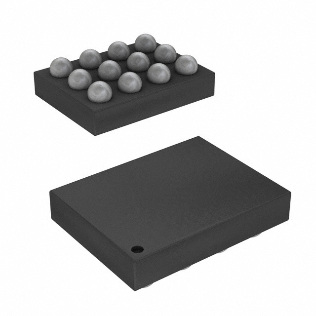
STMicroelectronics TCPP01-M12
- Part No.:
- TCPP01-M12
- Manufacturer:
- STMicroelectronics
- Category:
- Surge Suppression Ics
- Package:
- 12-VFQFN Exposed Pad
- Datasheet:
-
 TCPP01-M12.pdf
- Description:
- TYPE-C PORT PROTECTION 12QFN
- Quantity:
- Payment:

- Shipping:

Inventory:1,867
Please send an inquiry. Send us your inquiry, and we will respond immediately.
Product details
Overview
TCPP01-M12 from STMicroelectronics is a USB Type-C™ port protection IC designed for sink/UFP applications, providing adjustable VBUS overvoltage protection (5–22 V), 6.0 V CC-line OVP, ±8 kV/±15 kV IEC 61000-4-2 ESD protection on CC1/CC2, integrated N-MOSFET gate driver, and 0 nA quiescent current in cable-unplugged state - deployed in smart speakers, IoT gateways, and battery-powered consumer devices.
For engineers reviewing the TCPP01-M12 datasheet, TCPP01-M12 pinout, TCPP01-M12 application, or TCPP01-M12 equivalent, key selection considerations include VBUS OVP threshold adjustability via external resistor divider, dead-battery management logic compatibility with 3.3 V MCU GPIO control, CC-line short-to-VBUS response time (<70 ns), and QFN-12L package integration adjacent to USB-C receptacles.
Technical Context
The TCPP01-M12 implements dual-path overvoltage protection: a fast internal FET (RON = 1.2 Ω, tovp_cc = 70 ns) clamps CC1/CC2 during VBUS short events, while an external N-MOSFET-driven by an integrated charge pump and gate driver-is controlled via VBUS_CTRL to enforce adjustable VBUS OVP (Vovp_th = 1.27 V typical, hysteresis = 10%).
Its architecture separates signal-domain (CC1c/CC2c, CC1/CC2, DB/, FLT/) and power-domain (IN_GD, SOURCE, GATE, VBUS_CTRL) pins, enabling safe isolation between low-voltage MCU logic (3.3 V VCC) and up-to-22 V VBUS paths; dead-battery logic activates Rd resistors on CC lines when DB/ is pulled high by MCU GPIO, satisfying USB PD 3.1 SPR/PPS sink requirements.
Key Specifications
| Parameter | Value and Actual Design Meaning |
|---|---|
| VBUS OVP Range | Adjustable 5 V to 22 V via external resistor divider on VBUS_CTRL pin - enables system-level protection against defective chargers without redesigning power path. |
| CC-Line OVP Threshold | 6.0 V ±0.4 V (VTH_CC) - protects 5 V-tolerant USB-PD controller I/Os from VBUS shorts during hot-plug/unplug. |
| ESD Protection Level | IEC 61000-4-2 Level 4: ±8 kV contact / ±15 kV air on CC1c, CC2c, IN_GD - eliminates need for discrete TVS diodes at connector. |
| Quiescent Current | 0 nA when cable detached and DB/ = high - extends battery life in always-on sink devices like earphones and smart glasses. |
| Operating Junction Temp | −40 °C to +125 °C - supports industrial-grade thermal reliability in enclosed power tools and healthcare equipment. |
| CC-Line Bandwidth | 10 MHz at −3 dB - preserves USB PD communication integrity (e.g., SOP' packets) without signal distortion. |
| FLT/ Response Time | 5 µs propagation delay from OVP/OTP/UVLO event to open-drain fault flag assertion - enables fast system-level fault recovery. |
Pinout & Package
TCPP01-M12 is housed in a 3 mm × 3 mm, 0.4 mm pitch QFN-12L package with exposed thermal pad (GND). Its compact footprint allows placement within 2 mm of the USB Type-C™ receptacle for optimal high-frequency ESD and transient suppression.
| Pin/Terminal | Circuit Role | Design Meaning |
|---|---|---|
| CC1, CC2 | USB-PD controller interface | Connect to MCU's UCPD PHY CC pins; carry configuration channel signaling and dead-battery Rd resistors. |
| CC1c, CC2c | USB-C connector interface | Directly route to USB-C receptacle CC pins; host integrated OVP FET and ESD clamp network. |
| VBUS_CTRL | Analog input | Sets VBUS OVP threshold via resistor divider; 1.27 V reference enables precise 5–22 V adjustment. |
| GATE, SOURCE, IN_GD | N-MOSFET interface | Drive external N-channel MOSFET (SOURCE = MOSFET source, IN_GD = MOSFET drain input, GATE = gate drive output). |
| DB/ | Digital control input | MCU GPIO pin enabling dead-battery mode; high = activate Rd resistors, low = disable. |
| FLT/ | Fault reporting output | Open-drain flag asserted low on OVP/OTP/UVLO; pulls up externally to detect protection events. |
| VCC | Power supply input | 3.3 V ±0.3 V supply; powers internal logic; zero-consumption achieved when VCC = 0 V and DB/ = high. |
Key Features
| Feature | Design Value |
|---|---|
| Adjustable VBUS OVP | Enables single BOM across multiple input voltage requirements (5 V legacy to 20 V PPS) using one external resistor pair. |
| CC-line short-to-VBUS protection | Sub-70 ns response with 1.2 Ω ON resistance limits peak CC-line stress to <9.2 V during ±8 kV ESD + hot-plug transients. |
| Integrated N-MOSFET gate driver | Eliminates need for external level shifter or charge pump IC; supports lower-RDS(on) MOSFETs than P-channel alternatives, reducing conduction loss. |
| Zero-quiescent-current mode | DB/ pin control allows MCU to gate VCC supply, achieving true 0 nA standby - critical for multi-year battery life in wearables. |
| USB PD 3.1 SPR/PPS compliance | Supports programmable power supply negotiation (20 mV steps) and dead-battery detection per USB IF test ID 5205 certification. |
Applications
| Smart Audio Devices | IoT Edge Gateways |
|---|---|
Use Scenario: Wireless earphones and smart speakers drawing power from USB-C PD sources while maintaining multi-week battery life. IC Role / Device Role / Timing Role: Sink-side port protector managing VBUS OVP, CC-line ESD, and dead-battery handshake with STM32G0 MCU. Use Value: 0 nA quiescent current extends shelf life; ±15 kV air discharge rating ensures robustness during user handling. | Use Scenario: Industrial IoT gateways powered via USB-C PD in field-deployed edge nodes with intermittent connectivity. IC Role / Device Role / Timing Role: Front-end protection companion to STM32U5 UCPD controller, enforcing CC-line integrity during firmware updates over USB PD. Use Value: 10 MHz CC bandwidth preserves SOP' packet timing; QFN-12L placement near receptacle minimizes PCB trace inductance. |
| Portable Medical Sensors | USB-C Power Tools |
Use Scenario: Battery-powered glucose monitors and pulse oximeters requiring certified medical-grade ESD immunity and low-power operation. IC Role / Device Role / Timing Role: Isolates 3.3 V MCU domain from 20 V VBUS faults while supporting USB PD contract negotiation for fast charging. Use Value: IEC 61000-4-2 Level 4 compliance meets IEC 60601-1-2 ESD requirements; −40 °C to +125 °C operation supports sterilization cycles. | Use Scenario: Cordless drills and impact drivers with USB-C input for universal charging adapters and field-replaceable batteries. IC Role / Device Role / Timing Role: VBUS OVP supervisor triggering external N-MOSFET cutoff during 22 V surge events from damaged cables or chargers. Use Value: Adjustable 5–22 V OVP threshold accommodates both 5 V legacy adapters and 20 V PPS fast-charging profiles. |
Equivalent & Alternatives
The following parts are listed as comparable options for similar USB Type-C™ sink port protection applications.
| Alternative Part | Technical Difference | Application Difference | Selection Advice |
|---|---|---|---|
| TPS65987D | Integrated PD controller + port protection in single chip; no external MOSFET required but higher BOM cost and fixed 20 V VBUS OVP. | Targeted at full-featured DRP systems; lacks zero-quiescent-current mode and discrete CC OVP FET for ultra-low-power sink use cases. | Select when needing embedded PD policy engine; avoid when optimizing for battery life or cost-sensitive sink-only designs. |
| IP5306 | Monolithic USB-C power bank SoC with basic OVP; no CC-line short protection, no ESD certification, no DB/ logic or FLT/ flag. | Designed for portable power banks only; not qualified for industrial or medical USB-C sink applications requiring IEC 61000-4-2 Level 4. | Select only for low-cost consumer power banks; reject for any application requiring USB IF certification or robust CC-line protection. |
Compared with TPS65987D and IP5306, TCPP01-M12 uniquely delivers certified ESD immunity, sub-70 ns CC OVP response, and true 0 nA standby - making it the only choice for battery-constrained, USB IF-certified sink devices where external MCU handles PD protocol.
Availability
TCPP01-M12 is available at Aetrix Electronics and suitable for smart audio devices, IoT edge gateways, portable medical sensors, and USB-C power tools requiring stable component supply, long-term lifecycle support, and USB IF-certified port protection.
Supply support for TCPP01-M12 includes scheduled delivery planning, volume procurement assistance, BOM continuity management, traceable sourcing, and lifecycle availability coordination for OEM customers, industrial embedded developers, connected-device designers, and electronics production programs.
Manufacturer
STMicroelectronics is a global semiconductor leader headquartered in Geneva, Switzerland, delivering intelligent power, sensing, and control solutions across automotive, industrial, and consumer markets.
TCPP01-M12 belongs to ST's USB Type-C™ Port Protection product line, engineered specifically to simplify migration from legacy USB connectors to USB-C in cost-sensitive, battery-operated sink devices while meeting USB IF certification and IEC 61000-4-2 compliance.
FAQ
What is the function of the DB/ pin in TCPP01-M12?
The DB/ pin is a digital input that enables dead-battery management logic. When driven high by a 3.3 V MCU GPIO, it activates internal Rd resistors on CC1/CC2 lines to signal "dead battery" condition to the source during USB PD contract negotiation. It also gates VCC supply to achieve 0 nA quiescent current when no cable is attached.
Can TCPP01-M12 be used in source (DFP) applications?
Yes - TCPP01-M12 supports source configurations per its datasheet, providing VBUS OVP and CC-line protection. However, it lacks integrated PD policy engine or VCONN generation; it must be paired with a separate USB PD controller (e.g., STM32G4 with UCPD) and external VCONN LDO for full DFP functionality.
How does the FLT/ pin behave during overtemperature events?
The FLT/ pin is an open-drain output that pulls low within 5 µs of OTP activation. It remains low until junction temperature falls below the hysteresis threshold (~125 °C turn-off after ~145 °C turn-on), then returns to high-impedance state. External pull-up is required for microcontroller interrupt detection.
What external components are mandatory for basic TCPP01-M12 operation?
Mandatory components include: (1) resistor divider on VBUS_CTRL to set OVP threshold, (2) external N-channel MOSFET on VBUS path (SOURCE, GATE, IN_GD connections), (3) 100 nF/50 V capacitor on CBIAS pin for ESD filtering (per AN4871), and (4) external pull-up on FLT/ for fault monitoring. No bypass capacitor is required on VCC due to internal regulation.
TCPP01-M12 Specifications
- Product attributes
- Attribute value
- Manufacturer:
- STMicroelectronics
- Package/Case:
- 12-VFQFN Exposed Pad
- Series:
- -
- Packaging:
- Tape & Reel (TR)
- Product Status:
- Active
- Voltage - Clamping:
- -
- Technology:
- Internal Switch
- Number of Circuits:
- 2
- Applications:
- USB-C (USB TYPE-C)
- Grade:
- -
- Qualification:
- -
- Mounting Type:
- Surface Mount
- Supplier Device Package:
- 12-QFN (3x3)
TCPP01-M12 FAQ
1.How can I place an order for TCPP01-M12 through Aetrix?
Please submit a Request for Quotation (RFQ) for TCPP01-M12 on Aetrix. Our sales agent will provide a competitive quotation and guide you through the order confirmation once you accept the terms.
2.Are the price and stock information for TCPP01-M12 reliable?
The price and inventory of TCPP01-M12 are updated periodically and may fluctuate due to market conditions. Stock and pricing data are typically refreshed every 24 hours. Quotation validity for TCPP01-M12 is usually 5 days.
3.What payment methods are accepted for TCPP01-M12?
We accept Wire Transfer, PayPal, Credit Card, Western Union, MoneyGram, and Escrow for TCPP01-M12 transactions.
Note: Certain payment methods may incur a processing fee.
4.How is shipping managed for TCPP01-M12?
TCPP01-M12 orders can be shipped via leading logistics carriers, including DHL, UPS, FedEx, TNT, or Registered Mail.
Once your TCPP01-M12 order is processed, you will receive an email with the shipment details and tracking number.
Note: Tracking information may take up to 24 hours to appear. Express delivery typically takes 3–5 business days.
5.How can I obtain technical support or documentation for TCPP01-M12?
For technical support, including TCPP01-M12 datasheets, pinout diagrams, or application guidance, please contact our engineering support team. They can provide detailed documentation and assistance for your TCPP01-M12 requirements.
6.How does Aetrix verify that TCPP01-M12 is sourced from the original manufacturer or authorized distributors?
All TCPP01-M12 products on Aetrix are procured from qualified distributors and authorized channels. Our dedicated quality assurance team conducts strict verification, including traceability checks and, if necessary, third-party testing. This ensures that TCPP01-M12 meets industry standards.
7.What is the process for return or replacement of TCPP01-M12?
All TCPP01-M12 units undergo pre-shipment inspection (PSI). If there is an issue with TCPP01-M12, returns or replacements are accepted under the following conditions:
1.Quantity discrepancies, incorrect items, or visible external defects (such as breakage or corrosion), acknowledged by Aetrix.
2.The issue is reported within 90 days of delivery.
3.The TCPP01-M12 part is unused and in its original packaging.
Return procedure for TCPP01-M12:
1.Submit a request within 90 days.
2.Obtain a Return Material Authorization (RMA) from Aetrix.
TCPP01-M12 Tags
-
TVS3300DRVR
Texas Instruments

-
TCPP01-M12
STMicroelectronics
-
TPD4S214YFFR
Texas Instruments
-
TPD6S300ARUKR
Texas Instruments
-
TBU-CA085-300-WH
Bourns Inc.
-
TBU-CA065-500-WH
Bourns Inc.
-
TBU-CA040-100-WH
Bourns Inc.
-
TBU-CA085-500-WH
Bourns Inc.
-
TBU-CA085-200-WH
Bourns Inc.
-
NX20P0408UKZ
NXP USA Inc.
-
TBU-CA085-100-WH
Bourns Inc.
-
TBU-CA050-300-WH
Bourns Inc.
Tech Hub

Jumper cables guide covering safe connection order, red and black clamp placement, final ground connection, cable gauge, length, clamp quality, copper vs CCA cables, jump starter comparison and battery…

LDO regulator guide covering low dropout voltage, power dissipation, thermal design, PSRR, output noise, capacitor stability, adjustable LDO circuits, LDO vs buck converter and datasheet selection chec…

Conditional Access Module guide covering CAM meaning, CI/CI+ interface, smart card authorization, DVB security workflow, TV and set-top box compatibility, internal electronics, ESD protection, connecto…

Guide to electronic component obsolescence covering EOL risk, PCN/PDN notices, last-time buy planning, replacement options, form-fit-function validation, counterfeit risk and BOM lifecycle management.

18650 battery guide covering lithium-ion cell basics, 3.6V/3.7V voltage, 4.2V charging, mAh and Wh capacity, protected cells, chargers, BMS, series-parallel packs, holders, welding and sourcing checks.…

Hall effect sensor guide covering working principle, linear and digital sensors, Arduino circuits, current sensing, speed detection, automotive applications, A3144 examples, signal filtering and datash…

Product Change Notification guide for electronic components, covering PCN meaning, PCN vs PDN/EOL, common change types, risk levels, form-fit-function review, engineering validation, BOM control, LTB/L…

A practical guide to blend door actuators, covering HVAC function, symptoms, location, AC and heater issues, reset and calibration, replacement cost, electrical diagnosis, compatibility checks, and rep…

Engineering guide to Raspberry Pi alternatives, covering chip-level differences, Orange Pi, ROCK, Jetson, Banana Pi, NanoPi, Compute Module, Pico, GPIO, camera, HAT compatibility, and replacement risks…

Engineering guide to dynamic load response testing for high-current buck converters, covering load step setup, slew rate, Vcore undershoot, overshoot, recovery time, probe location, output capacitors a…


