
 My Inquiry
 My Account


Microchip Technology EEC1005-I/WC-UB1
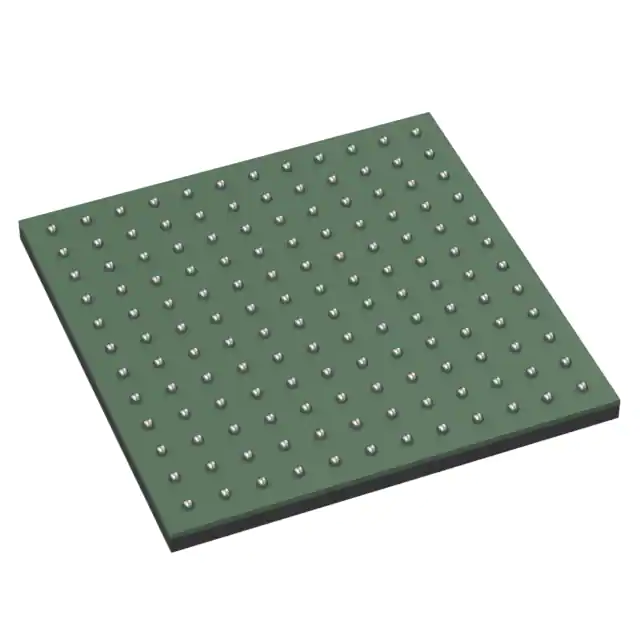
- Part No.:
- EEC1005-I/WC-UB1
- Manufacturer:
- Microchip Technology
- Category:
- Application Specific Microcontrollers
- Package:
- 144-WFBGA
- Datasheet:
-
 EEC1005-I/WC-UB1.pdf
- Description:
- UBM CONTROLLER, 144-PIN, SFF-TA-
- Quantity:
- Payment:

- Shipping:

Inventory:3,132
Please send an inquiry. Send us your inquiry, and we will respond immediately.
Product details
Overview
EEC1005-I/WC-UB1 from Microchip Technology is a universal storage backplane management processor implementing SFF-TA-1005 UBM over I²C, supporting SFF-8654 HFC and SFF-8639/SFF-TA-1001 DFCs for SAS/SATA/NVMe drives, with hardware-accelerated SGPIO (up to 4 interfaces), secure boot (AES-256/ECDSA/SHA-256), and integrated FRU memory for up to 6 host-facing connectors in enterprise server backplanes.
For engineers reviewing the EEC1005-I/WC-UB1 datasheet, EEC1005-I/WC-UB1 pinout, EEC1005-I/WC-UB1 application, or EEC1005-I/WC-UB1 equivalent, key selection criteria include UBM/SGPIO interface configurability via analog CONFIG_PIN, NVMe hot-plug and PERST control per DFC, SFF-8489-compliant LED management for up to 16 drives, and dual-package support (84-pin/144-pin WFBGA) with RoHS compliance.
Technical Context
The EEC1005-I/WC-UB1 implements a firmware-configurable UBM controller architecture that routes sideband signals (IFDET, PRSNT, PERST) between host-facing connectors (HFCs) and drive-facing connectors (DFCs), with dedicated hardware logic for SES-over-UBM and SGPIO legacy translation. It supports both direct-attach (BMC-managed) and host-attach (HBA-managed) topologies.
Configuration is determined at power-up by an analog voltage on the CONFIG_PIN, selecting among 14 predefined modes-including 4/8/12/16-drive SGPIO-only, U.2/U.3 UBM-only, or hybrid UBM+SGPIO-each mapping to specific pinouts (84-pin or 144-pin WFBGA), HFC/DFC counts, and protocol support (SAS/SATA vs PCIe/NVMe).
Key Specifications
| Parameter | Value and Actual Design Meaning |
|---|---|
| UBM Compliance | Fully implements SFF-TA-1005 Universal Backplane Management protocol over I²C for host communication. |
| Drive Support | Scalable to 16 SAS/SATA drives via SGPIO or 12 NVMe drives via UBM; supports U.2 and U.3 DFCs per SFF-8639/SFF-TA-1001. |
| Interface Count | Up to 8 I²C ports: 6 for UBM HFCs, 1 for BMC, 1 for generic FRU; plus up to 4 hardware-accelerated SGPIO controllers. |
| Secure Boot | Hardware-accelerated AES-256 decryption, ECDSA P-256 signature verification, and SHA-256 hashing authenticate firmware before execution. |
| FRU Memory | Integrated non-volatile memory: 256-byte Configuration FRU (I²C 0x54), 256-byte Generic FRU (I²C 0x54), and per-HFC UBM FRUs (I²C 0xAE). |
| LED Control | Supports SFF-8489 IBPI patterns (online/fault/locate/rebuild/PFA) with programmable blink periods and custom patterns stored in FRU. |
| PERST Handling | Dedicated PERST# signal per DFC enables direct host-controlled NVMe reset without latency or external logic. |
Pinout & Package
EEC1005-I/WC-UB1 is supplied in an 84-pin WFBGA RoHS-compliant package (5.0 mm × 5.0 mm, 0.5 mm pitch), as confirmed in DS00003392B-page 4 and page 12 Table 3-1 (Config ID 05–08). Pin functions are configuration-dependent and defined in Tables 10-3 and 10-4 of the datasheet.
| Pin/Terminal | Circuit Role | Design Meaning |
|---|---|---|
| CONFIG_PIN | Analog configuration input | Samples resistor-divider voltage at startup to select one of 14 supported backplane configurations (e.g., 4-drive SGPIO or 8-drive U.3 UBM). |
| HFC_I2C_SDA/SCL | UBM host interface bus | I²C bidirectional lines for UBM command/response traffic with host (SFF-TA-1005 compliant, slave address 0xAE per HFC). |
| BMC_I2C_SDA/SCL | BMC management interface | Separate I²C bus (7-bit address 0x54) for FRU read/write, firmware updates, and system-level monitoring by baseboard manager. |
| SGPIO_CLK/DATA/LOAD/STROBE | SGPIO sideband interface | Four independent hardware-accelerated SGPIO controllers supporting SAS/SATA backplane signaling per SFF-8485. |
| IFDET#/PRSNT#/PERST# | Drive presence & control | Dedicated per-DFC signals: IFDET# detects drive insertion, PRSNT# confirms physical presence, PERST# enables host-initiated NVMe reset. |
| LEDn_ON/LEDn_FAULT | LED driver outputs | Open-drain outputs driving green (online) and amber (fault) LEDs per drive slot per SFF-8489 IBPI specification. |
Key Features
| Feature | Design Value |
|---|---|
| Configurable Interface Mode | Single CONFIG_PIN selects between SGPIO-only, UBM-only, or hybrid UBM+SGPIO operation - eliminating need for multiple BOM variants. |
| Hardware-Accelerated SGPIO | Four independent SGPIO controllers offload timing-critical sideband signaling from firmware, enabling reliable SAS/SATA drive enumeration at scale. |
| Per-DFC PERST Control | Dedicated PERST# output per drive-facing connector allows precise, low-latency NVMe reset without shared bus contention or external buffers. |
| Multi-FRU Architecture | Three distinct FRU spaces - Configuration (0x54), Generic (0x54), and per-HFC UBM (0xAE) - enable field-upgradable identity, customer data, and standards-compliant backplane reporting. |
| Secure Firmware Lifecycle | AES-256/ECDSA/SHA-256 crypto accelerators + lockable OTP support authenticated boot, secure OTA updates, and cryptographic key revocation. |
Applications
| Enterprise Server Backplanes | Modular Storage Enclosures |
|---|---|
Use Scenario: High-density 2U/4U rack servers with mixed SAS/SATA/NVMe drive bays requiring centralized enclosure management and LED status indication. IC Role / Device Role / Timing Role: UBM controller interfacing with HBA/BMC over I²C and SGPIO to report drive presence, health, and activity while managing per-slot LEDs per SFF-8489. Use Value: Enables single-chip support for up to 12 NVMe drives (U.3) or 16 SAS/SATA drives (SGPIO), reducing bill-of-materials and PCB area versus discrete solutions. | Use Scenario: Carrier-grade storage enclosures with hot-swap bays, redundant power, and multi-chassis scalability across JBOD or RAID systems. IC Role / Device Role / Timing Role: Backplane management hub coordinating drive insertion/removal detection (IFDET/PRSNT), NVMe PERST sequencing, and SES-over-UBM commands across multiple DFCs. Use Value: Supports Y-cable PCIe lane splitting and multi-backplane chassis configurations, allowing flexible topology expansion without redesigning management firmware. |
| Direct-Attach BMC-Managed Systems | U.3 Enterprise SSD Racks |
Use Scenario: Edge servers or micro-datacenters where the baseboard management controller (BMC) directly manages storage drives without an HBA. IC Role / Device Role / Timing Role: UBM controller operating in BMC-emulation mode, responding to standard UBM commands over dedicated I²C while providing FRU-based drive identity. Use Value: Eliminates need for HBA-side UBM stack; BMC uses same SFF-TA-1005 protocol to manage drives, simplifying software integration and certification. | Use Scenario: High-performance compute racks using U.3 form factor SSDs with PCIe Gen4/Gen5 lanes and advanced thermal/power management. IC Role / Device Role / Timing Role: UBM controller for U.3 DFCs implementing SFF-TA-1001, handling drive power disable, PERST coordination, and SFF-8489 locate/blink patterns during maintenance. Use Value: Full U.3 feature support (including IFDET2) ensures compatibility with next-gen enterprise SSDs while maintaining backward compatibility with U.2 infrastructure. |
Equivalent & Alternatives
The following parts are listed as comparable options for similar backplane management applications.
| Alternative Part | Technical Difference | Application Difference | Selection Advice |
|---|---|---|---|
| Microchip EEC1005-I/WC-UB2 | Same die, 144-pin WFBGA package supporting up to 16-drive SGPIO or full-feature 8-drive U.3 UBM configurations not available in 84-pin variant. | Required for designs needing >8 DFCs, >4 HFCs, or hybrid UBM+SGPIO modes (e.g., Config ID 0D); larger footprint and higher pin count. | Select EEC1005-I/WC-UB2 when scaling beyond 8 drives or requiring full U.3 feature set including IFDET2 support in high-density layouts. |
| ON Semiconductor NIS5130MN | Dedicated SGPIO expander IC (no UBM, no FRU, no crypto, no PERST control); supports only SAS/SATA sideband signaling with fixed 8-port configuration. | Limited to legacy SAS/SATA backplanes without NVMe support, secure boot, or LED pattern customization; no U.2/U.3 DFC management capability. | Choose NIS5130MN only for cost-sensitive, low-complexity SAS/SATA-only systems where UBM compliance and NVMe features are unnecessary. |
Compared with EEC1005-I/WC-UB1, the -UB2 offers expanded drive/HFC capacity in a larger package, while the NIS5130MN provides minimal SGPIO functionality without UBM, security, or NVMe support - making EEC1005-I/WC-UB1 the only option meeting full SFF-TA-1005, U.3, and secure firmware requirements in compact 84-pin WFBGA.
Availability
EEC1005-I/WC-UB1 is available at Aetrix Electronics and suitable for enterprise server backplanes, modular storage enclosures, direct-attach BMC-managed systems, and U.3 enterprise SSD racks requiring stable component supply, long-term lifecycle support, and RoHS-compliant packaging.
Supply support for EEC1005-I/WC-UB1 includes scheduled delivery planning, volume procurement assistance, BOM continuity management, traceable sourcing, and lifecycle availability coordination for OEM customers, industrial embedded developers, connected-device designers, and electronics production programs.
Manufacturer
Microchip Technology Inc. is a leading provider of microcontrollers, analog components, FPGAs, and security solutions, serving automotive, industrial, communications, and computing markets with vertically integrated silicon and software.
The EEC1005 product line delivers enterprise-grade backplane management processors designed specifically for SFF-compliant storage systems, integrating UBM, SGPIO, secure boot, and multi-FRU capabilities into a single configurable IC.
FAQ
What is the primary function of the EEC1005-I/WC-UB1 in a storage system?
The EEC1005-I/WC-UB1 serves as a universal backplane management processor that implements SFF-TA-1005 UBM over I²C to coordinate communication between host systems (HBA/BMC) and storage drives (SAS/SATA/NVMe). It handles drive presence detection (IFDET/PRSNT), NVMe reset control (PERST), LED status indication per SFF-8489, and FRU-based identity reporting - all within a single 84-pin WFBGA package.
How does the CONFIG_PIN on the EEC1005-I/WC-UB1 determine device behavior?
The CONFIG_PIN on the EEC1005-I/WC-UB1 samples an analog voltage at power-up to select one of 14 predefined configurations - such as 4-drive SGPIO, 8-drive U.2 UBM, or hybrid UBM+SGPIO - each defining HFC/DFC count, interface type, and pin mapping. This eliminates firmware reprogramming and enables hardware-defined backplane variants using resistor-divider networks per DS00003392B-page 8–9.
Does the EEC1005-I/WC-UB1 support both U.2 and U.3 drive connectors?
Yes, the EEC1005-I/WC-UB1 supports both U.2 and U.3 drive-facing connectors per SFF-8639 and SFF-TA-1001 specifications. Configurations 08 and 09 (U.3) explicitly include IFDET2 support for U.3-specific drive detection, while configurations 05–07 (U.2) provide full SFF-8639 compliance - all implemented in the same EEC1005-I/WC-UB1 silicon with package-dependent pinout.
What security features are implemented in the EEC1005-I/WC-UB1?
The EEC1005-I/WC-UB1 integrates hardware-accelerated AES-256 decryption, ECDSA P-256 signature verification, and SHA-256 hashing to authenticate firmware during secure boot. It also supports secure firmware updates, cryptographic key revocation, and lockable OTP storage for private keys - ensuring trusted execution and protection against unauthorized code injection throughout the device lifecycle.
Can the EEC1005-I/WC-UB1 manage LED indicators for more than eight drives?
Yes, the EEC1005-I/WC-UB1 supports LED management for up to 16 drives when configured in SGPIO mode (e.g., Config ID 03 or 04), using its four hardware-accelerated SGPIO controllers. Each controller drives up to four drive slots with SFF-8489-compliant online/fault/locate/rebuild patterns, and custom blink periods can be programmed via the Configuration FRU at addresses 0xBD–0xFF.
EEC1005-I/WC-UB1 Specifications
- Product attributes
- Attribute value
- Manufacturer:
- Microchip Technology
- Series:
- -
- Package/Case:
- 144-WFBGA
- Packaging:
- Tray
- Product Status:
- Active
- Programmable:
- Not Verified
- Applications:
- Storage Backplane Management
- Core Processor:
- -
- Program Memory Type:
- -
- Controller Series:
- -
- RAM Size:
- -
- Interface:
- I2C
- Number of I/O:
- -
- Voltage - Supply:
- -
- Operating Temperature:
- -40°C ~ 85°C
- Grade:
- -
- Qualification:
- -
- Mounting Type:
- Surface Mount
- Supplier Device Package:
- 144-WFBGA (10x10)
EEC1005-I/WC-UB1 FAQ
1.How can I place an order for EEC1005-I/WC-UB1 through Aetrix?
Please submit a Request for Quotation (RFQ) for EEC1005-I/WC-UB1 on Aetrix. Our sales agent will provide a competitive quotation and guide you through the order confirmation once you accept the terms.
2.Are the price and stock information for EEC1005-I/WC-UB1 reliable?
The price and inventory of EEC1005-I/WC-UB1 are updated periodically and may fluctuate due to market conditions. Stock and pricing data are typically refreshed every 24 hours. Quotation validity for EEC1005-I/WC-UB1 is usually 5 days.
3.What payment methods are accepted for EEC1005-I/WC-UB1?
We accept Wire Transfer, PayPal, Credit Card, Western Union, MoneyGram, and Escrow for EEC1005-I/WC-UB1 transactions.
Note: Certain payment methods may incur a processing fee.
4.How is shipping managed for EEC1005-I/WC-UB1?
EEC1005-I/WC-UB1 orders can be shipped via leading logistics carriers, including DHL, UPS, FedEx, TNT, or Registered Mail.
Once your EEC1005-I/WC-UB1 order is processed, you will receive an email with the shipment details and tracking number.
Note: Tracking information may take up to 24 hours to appear. Express delivery typically takes 3–5 business days.
5.How can I obtain technical support or documentation for EEC1005-I/WC-UB1?
For technical support, including EEC1005-I/WC-UB1 datasheets, pinout diagrams, or application guidance, please contact our engineering support team. They can provide detailed documentation and assistance for your EEC1005-I/WC-UB1 requirements.
6.How does Aetrix verify that EEC1005-I/WC-UB1 is sourced from the original manufacturer or authorized distributors?
All EEC1005-I/WC-UB1 products on Aetrix are procured from qualified distributors and authorized channels. Our dedicated quality assurance team conducts strict verification, including traceability checks and, if necessary, third-party testing. This ensures that EEC1005-I/WC-UB1 meets industry standards.
7.What is the process for return or replacement of EEC1005-I/WC-UB1?
All EEC1005-I/WC-UB1 units undergo pre-shipment inspection (PSI). If there is an issue with EEC1005-I/WC-UB1, returns or replacements are accepted under the following conditions:
1.Quantity discrepancies, incorrect items, or visible external defects (such as breakage or corrosion), acknowledged by Aetrix.
2.The issue is reported within 90 days of delivery.
3.The EEC1005-I/WC-UB1 part is unused and in its original packaging.
Return procedure for EEC1005-I/WC-UB1:
1.Submit a request within 90 days.
2.Obtain a Return Material Authorization (RMA) from Aetrix.
EEC1005-I/WC-UB1 Tags

-
CYPD3175-24LQXQ
Infineon Technologies

-
SLB9672VU20FW1523XTMA1
Infineon Technologies

-
SLB9670VQ20FW785XTMA1
Infineon Technologies
-
SLB9672XU20FW1523XTMA1
Infineon Technologies
-
SLB9673XU20FW2613XTMA1
Infineon Technologies

-
CYPD3125-40LQXIT
Infineon Technologies

-
AT97SC3204-U2A1A-20
Microchip Technology
-
AT97SC3204-U2A1A-10
Microchip Technology
-
SLM9670AQ20FW1311XTMA1
Infineon Technologies
-
SLB9672XU20FW1613XTMA1
Infineon Technologies
-
SLB9672AU20FW1613XTMA1
Infineon Technologies
-
SLB9673AU20FW2613XTMA1
Infineon Technologies
Tech Hub

TTL and CMOS logic families differ in thresholds, loading, output drive, power and timing. This engineering guide compares 74HC and 74HCT, calculates noise margins and checks 3.3 V/5 V compatibility.

A practical engineering guide to 3.3V and 5V logic compatibility, input thresholds, resistor dividers, translator ICs, MOSFET level shifting, I2C pull-ups, timing limits and power-sequencing risks.

The 74HC595 uses push-pull logic outputs, while the TPIC6B595 uses 50 V open-drain DMOS sinks for higher-power loads. This guide compares timing, current limits, 3.3 V interfacing, load wiring, thermal…

The 74HC595 converts serial data into eight stable parallel outputs. This guide covers pin functions, shift and storage timing, OE and MR behavior, drive-current limits, cascading, voltage compatibilit…

A technical comparison of level-sensitive latches and edge-triggered flip-flops, covering timing windows, setup and hold limits, master–slave operation, time borrowing, race-through, HDL inference and…

A D latch stores one bit while Enable controls when data can pass. This reference covers gate-level operation, truth tables, transparency, setup and hold timing, LE versus OE, common ICs and practical …

An SR latch stores one bit through cross-coupled feedback. This engineering reference covers NOR and NAND implementations, truth tables, forbidden-state recovery, gated operation, switch debouncing, fa…

Latch circuits retain one bit through feedback. This technical reference covers SR and D latches, truth tables, transparency, timing limits, latch-versus-flip-flop behavior, applications and common log…

An engineering guide to LED driver operation, constant-current and constant-voltage outputs, linear and switching topologies, dimming, IC selection, calculations, replacement compatibility, and fault c…

Operational amplifier guide covering op amp basics, feedback, ideal vs real op amps, common configurations, buffer circuits, offset, bias current, gain-bandwidth, slew rate, rail-to-rail limits and sel…


