
 My Inquiry
 My Account


NXP Semiconductors FXPS7140P7T1
- Part No.:
- FXPS7140P7T1
- Manufacturer:
- NXP Semiconductors
- Category:
- Pressure Sensors, Transducers
- Package:
- 16-QFN Exposed Pad
- Datasheet:
-
 FXPS7140P7T1.pdf
- Description:
- AUTOMOTIVE SAFETY PRESSURE SENSO
- Quantity:
- Payment:

- Shipping:

Inventory:1,167
Please send an inquiry. Send us your inquiry, and we will respond immediately.
Product details
Overview
FXPS7140P7T1 from NXP Semiconductors is a PSI5-only absolute and relative pressure sensor IC for automotive and industrial systems, delivering 40–140 kPa absolute pressure range, ±7.0 % accuracy over –40 °C to 85 °C, and dual-mode PSI5 communication at 125 kBd or 189 kBd. It integrates redundant capacitive transducers, sigma-delta ADC with sinc filter, and configurable low-pass filtering (370 Hz/400 Hz/800 Hz/1000 Hz) for PABS, plus 0.16 Hz LPF for P0 reference output.
For engineers reviewing the FXPS7140P7T1 datasheet, FXPS7140P7T1 pinout, FXPS7140P7T1 application, or FXPS7140P7T1 equivalent, this page provides verified technical context, validated pin functions, real-world use cases in brake, turbo, and HVAC systems, and two confirmed alternative parts with documented functional and protocol-level differences.
Technical Context
The FXPS7140P7T1 implements a dual-capacitor pressure transducer with anti-aliasing filter, sigma-delta ADC, and programmable IIR low-pass filters for absolute pressure (370 Hz 2-pole, 400 Hz 3-pole, 800 Hz/1000 Hz 4-pole) and a dedicated 0.16 Hz 1-pole LPF for P0 output. Its DSP supports 10-bit ΔP/P0 relative pressure reporting.
It operates exclusively in PSI5 v2.1 mode-supporting P10P-500/3L, P10P-500/4H, A10P-228/1L, and P10CRC-xxx/xx protocols-with programmable time slots (1 µs resolution), selectable error detection (even parity or 3-bit CRC), and two-wire programming. Unlike FXPS71407, it is factory-programmed for PSI5 only and not field-configurable to DSI3.
Key Specifications
| Parameter | Value and Actual Design Meaning |
|---|---|
| Absolute Pressure Range | 40 kPa to 140 kPa - covers full atmospheric to boosted intake and brake vacuum applications |
| Accuracy | ±7.0 % (PREL) - guaranteed over –40 °C to 85 °C for lifetime operation |
| Operating Temperature | –40 °C to 125 °C - qualified for under-hood automotive environments |
| Communication Protocol | PSI5 v2.1 only - no DSI3 capability; fixed at factory |
| Data Output Resolution | 10-bit ΔP/P0 - enables high-ratio relative pressure monitoring without external scaling |
| Filter Options | Selectable 370 Hz (2-pole), 400 Hz (3-pole), 800 Hz/1000 Hz (4-pole) LPF for PABS; 0.16 Hz (1-pole) LPF for P0 - allows dynamic response tuning per system noise profile |
| Baud Rate | 125 kBd or 189 kBd - supports both legacy and high-speed PSI5 bus timing |
Pinout & Package
Packaged in Pb-free HQFN16 (SOT1573-2(SC)), 4 mm × 4 mm × 1.98 mm, thermal-enhanced quad flat no-lead package with 0.8 mm pitch and exposed die attach pad (Pin 17) requiring VSS connection.
| Pin/Terminal | Circuit Role | Design Meaning |
|---|---|---|
| BUS_O (Pin 1) | Supply out | Provides daisy-chain supply to next slave; must be unterminated in PSI5 mode per NXP recommendation |
| BUSSW_H (Pin 2) | High-side bus switch driver | Unused in PSI5 mode; recommended unterminated or tied to VSS |
| BUSSW_L (Pins 3, 5) | Low-side bus switch driver | Drives N-channel FET gate for PSI5 daisy chain; requires external pulldown resistor |
| BUSRTN/VSS (Pins 4, 15) | Supply return | Primary ground reference nodes for power and signal integrity |
| VBUF (Pin 13) | Power supply buffer | Feeds internal regulators; requires external decoupling capacitor to VSS per Figure 59/61 |
| BUS_I/VCC (Pin 16) | Supply and communication | Single-pin power input and PSI5 current-modulated data line; requires external capacitor to BUSRTN |
| PAD (Pin 17) | Die attach pad | Thermal and electrical ground; must be soldered to PCB VSS plane per Section 12.1 |
Key Features
| Feature | Design Value |
|---|---|
| Redundant pressure transducers | Two independent capacitive sensing elements improve fault tolerance and enable self-diagnostic cross-checking |
| Programmable PSI5 time slots | 1 µs resolution timing control allows precise synchronization in multi-sensor daisy chains |
| Configurable error detection | Selectable even parity or 3-bit CRC ensures robust data integrity in electrically noisy automotive buses |
| Dedicated P0 low-pass filter | 0.16 Hz 1-pole LPF isolates stable reference pressure for accurate ΔP/P0 ratio computation |
| OTP user-programmable registers | Three OTP regions (UF0–UF2) support permanent calibration storage, device identification, and traceability data |
Applications
| Brake System Vacuum Monitoring | Turbocharger Boost Control |
|---|---|
Use Scenario: Real-time vacuum level measurement in hydraulic brake boosters to detect assist loss or leak conditions. IC Role / Device Role / Timing Role: Absolute pressure sensor providing 40–140 kPa output with ±7.0 % accuracy; communicates via PSI5 at 125 kBd on shared vehicle bus. Use Value: Enables fail-safe brake assist diagnostics and meets ASIL-B functional safety requirements through built-in continuity monitor and register-level error flags. |
Use Scenario: Closed-loop boost pressure regulation in gasoline direct injection engines using turbocharged air intake. IC Role / Device Role / Timing Role: High-stability absolute pressure transducer with 1000 Hz LPF option for fast transient response; outputs calibrated PABS and ΔP/P0 via PSI5 daisy chain. Use Value: Supports rapid pressure feedback for ECU-based wastegate actuation, reducing turbo lag while maintaining emission compliance. |
| HVAC Cabin Pressure Regulation | Engine Crankcase Ventilation (PCV) |
Use Scenario: Maintaining cabin pressure differential during high-speed driving or altitude changes in premium vehicle HVAC systems. IC Role / Device Role / Timing Role: Relative pressure sensor delivering 10-bit ΔP/P0 output; uses 370 Hz 2-pole LPF to reject airflow noise while preserving slow cabin pressure drift. Use Value: Enables quiet, responsive blower control and occupant comfort without false triggers from transient wind gusts or door slams. |
Use Scenario: Monitoring crankcase pressure rise to detect piston ring wear or PCV valve blockage in diesel and gasoline engines. IC Role / Device Role / Timing Role: Absolute pressure sensor operating at –40 °C to 125 °C; reports PABS via PSI5 with 400 Hz 3-pole LPF to suppress combustion-induced pulsations. Use Value: Provides early warning of engine degradation by detecting abnormal pressure buildup before oil contamination or seal failure occurs. |
Equivalent & Alternatives
The following parts are listed as comparable options for similar PSI5 pressure sensor applications.
| Alternative Part | Technical Difference | Application Difference | Selection Advice |
|---|---|---|---|
| FXPS71407T1 | DSI3/PSI5 dual-mode; one-time programmable to PSI5; includes DSI3 discovery/command modes | Supports mixed-protocol networks and physical location identification; higher software stack complexity | Select FXPS71407T1 when system requires DSI3 compatibility or future protocol flexibility |
| MPX5704D | Analog output (0.2–4.7 V); no digital interface; requires external ADC and microcontroller | Lacks bus integration, diagnostics, and daisy-chaining; limited to point-to-point analog sensing | Select MPX5704D only for cost-sensitive, non-networked legacy designs without functional safety requirements |
Compared with FXPS7140P7T1, FXPS71407T1 adds DSI3 configurability at the cost of increased firmware overhead, while MPX5704D sacrifices digital bus features and built-in diagnostics for analog simplicity-making FXPS7140P7T1 optimal for new PSI5-only automotive subsystems requiring ASIL-ready integrated sensing.
Availability
FXPS7140P7T1 is available at Aetrix Electronics and suitable for brake vacuum monitoring, turbo boost control, HVAC cabin pressure regulation, and engine crankcase ventilation applications requiring stable component supply across automotive production lifecycles.
Supply support for FXPS7140P7T1 includes scheduled delivery planning, volume procurement assistance, BOM continuity management, traceable sourcing, and lifecycle availability coordination for OEM customers, industrial embedded developers, connected-device designers, and electronics production programs.
Manufacturer
NXP Semiconductors is a global semiconductor leader specializing in secure connectivity solutions for automotive, industrial, and IoT markets, with deep expertise in sensor signal conditioning and automotive serial interfaces.
The FXPS7140P7T1 belongs to NXP's PSI5/DSI3 pressure sensor family, designed specifically for ASIL-B compliant automotive subsystems where robustness, diagnostic coverage, and bus-integrated pressure sensing are critical.
FAQ
What communication protocols does the FXPS7140P7T1 support?
The FXPS7140P7T1 supports PSI5 version 2.1 only-it is factory-programmed exclusively for PSI5 operation and cannot be configured for DSI3. Supported PSI5 modes include P10P-500/3L, P10P-500/4H, A10P-228/1L, and P10CRC-xxx/xx. Unlike the FXPS71407 variant, FXPS7140P7T1 lacks DSI3 discovery, command-response, or background diagnostics functionality.
What is the pressure accuracy specification for FXPS7140P7T1 over temperature?
The FXPS7140P7T1 guarantees ±7.0 % accuracy over the –40 °C to 85 °C temperature range for its entire operational lifetime. This specification applies to the 40 kPa to 140 kPa absolute pressure range and is validated per NXP's PREL (preliminary) characterization. Accuracy outside this range or beyond 85 °C is not guaranteed.
Does FXPS7140P7T1 include built-in diagnostics and fault reporting?
Yes, FXPS7140P7T1 includes multiple hardware-level diagnostics: continuity monitor (CONT_ERR), internal regulator voltage monitors (VBUFUV_ERR, BUSINUV_ERR, INTREGA_ERR), oscillator training error (OSCTRAIN_ERR), and OTP array integrity checks (F_OTP_ERR, U_OTP_ERR). All status flags are accessible via read-only DEVSTAT registers ($01–$04) and reported in PSI5 status fields.
How is the P0 reference pressure handled in FXPS7140P7T1?
The FXPS7140P7T1 computes P0 using a dedicated 0.16 Hz, 1-pole low-pass filter to generate a stable baseline pressure reference. This P0 value is used internally to calculate the 10-bit ΔP/P0 relative pressure output. The P0 filter is separate from the configurable absolute pressure filters (370 Hz/400 Hz/800 Hz/1000 Hz) and cannot be disabled or reconfigured.
What are the key PCB layout requirements for FXPS7140P7T1?
FXPS7140P7T1 requires strict adherence to NXP's footprint guidelines: the exposed die attach pad (Pin 17) must be soldered to a solid VSS copper pour; BUS_I/VCC (Pin 16) needs a local 100 nF ceramic capacitor to BUSRTN; VBUF (Pin 13) requires a dedicated 1 µF capacitor to VSS; and BUSSW_L pins (3, 5) need external pulldown resistors for PSI5 daisy chain operation per Figure 61.
FXPS7140P7T1 Specifications
- Product attributes
- Attribute value
- Manufacturer:
- NXP Semiconductors
- Series:
- -
- Package/Case:
- 16-QFN Exposed Pad
- Packaging:
- Tape & Reel (TR)
- Product Status:
- Active
- Applications:
- Board Mount
- Pressure Type:
- Absolute
- Operating Pressure:
- 5.8PSI ~ 20.31PSI (40kPa ~ 140kPa)
- Output Type:
- -
- Output:
- -
- Accuracy:
- -
- Voltage - Supply:
- -
- Port Size:
- -
- Port Style:
- No Port
- Features:
- -
- Termination Style:
- -
- Maximum Pressure:
- -
- Operating Temperature:
- -40°C ~ 125°C
- Grade:
- -
- Qualification:
- -
- Mounting Type:
- Surface Mount, Wettable Flank
- Supplier Device Package:
- 16-HQFN (4x4)
FXPS7140P7T1 FAQ
1.How can I place an order for FXPS7140P7T1 through Aetrix?
Please submit a Request for Quotation (RFQ) for FXPS7140P7T1 on Aetrix. Our sales agent will provide a competitive quotation and guide you through the order confirmation once you accept the terms.
2.Are the price and stock information for FXPS7140P7T1 reliable?
The price and inventory of FXPS7140P7T1 are updated periodically and may fluctuate due to market conditions. Stock and pricing data are typically refreshed every 24 hours. Quotation validity for FXPS7140P7T1 is usually 5 days.
3.What payment methods are accepted for FXPS7140P7T1?
We accept Wire Transfer, PayPal, Credit Card, Western Union, MoneyGram, and Escrow for FXPS7140P7T1 transactions.
Note: Certain payment methods may incur a processing fee.
4.How is shipping managed for FXPS7140P7T1?
FXPS7140P7T1 orders can be shipped via leading logistics carriers, including DHL, UPS, FedEx, TNT, or Registered Mail.
Once your FXPS7140P7T1 order is processed, you will receive an email with the shipment details and tracking number.
Note: Tracking information may take up to 24 hours to appear. Express delivery typically takes 3–5 business days.
5.How can I obtain technical support or documentation for FXPS7140P7T1?
For technical support, including FXPS7140P7T1 datasheets, pinout diagrams, or application guidance, please contact our engineering support team. They can provide detailed documentation and assistance for your FXPS7140P7T1 requirements.
6.How does Aetrix verify that FXPS7140P7T1 is sourced from the original manufacturer or authorized distributors?
All FXPS7140P7T1 products on Aetrix are procured from qualified distributors and authorized channels. Our dedicated quality assurance team conducts strict verification, including traceability checks and, if necessary, third-party testing. This ensures that FXPS7140P7T1 meets industry standards.
7.What is the process for return or replacement of FXPS7140P7T1?
All FXPS7140P7T1 units undergo pre-shipment inspection (PSI). If there is an issue with FXPS7140P7T1, returns or replacements are accepted under the following conditions:
1.Quantity discrepancies, incorrect items, or visible external defects (such as breakage or corrosion), acknowledged by Aetrix.
2.The issue is reported within 90 days of delivery.
3.The FXPS7140P7T1 part is unused and in its original packaging.
Return procedure for FXPS7140P7T1:
1.Submit a request within 90 days.
2.Obtain a Return Material Authorization (RMA) from Aetrix.
FXPS7140P7T1 Tags
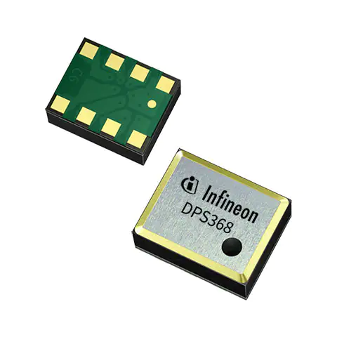
-
DPS368XTSA1
Infineon Technologies
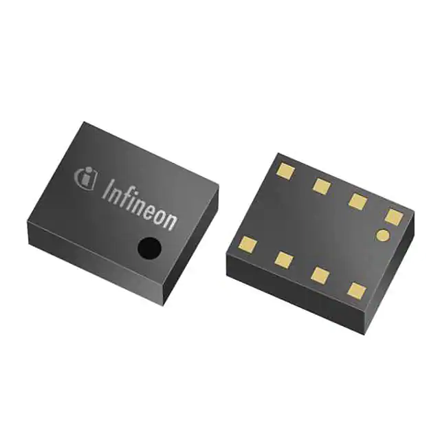
-
DPS310XTSA1
Infineon Technologies
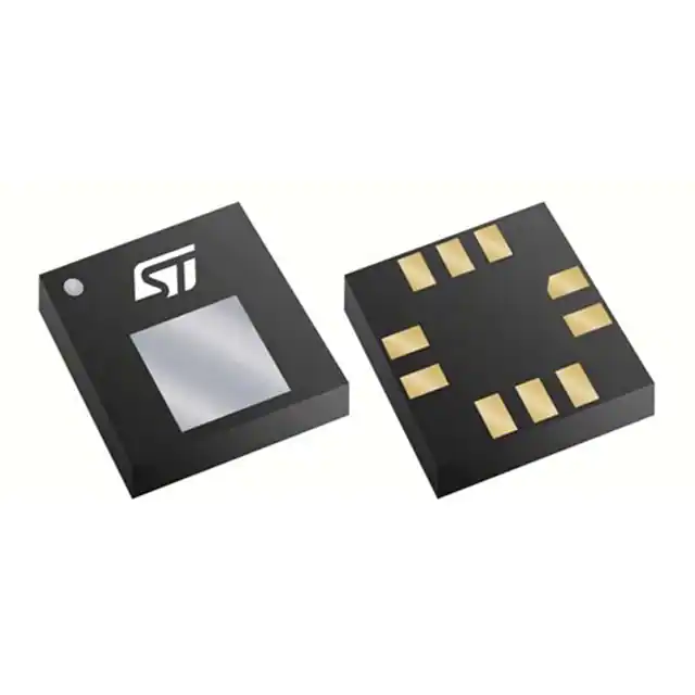
-
LPS22HHTR
STMicroelectronics

-
ICP-20100
TDK InvenSense
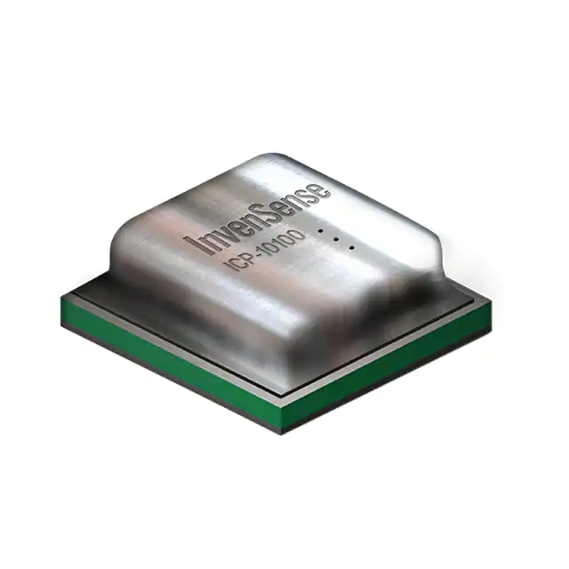
-
ICP-10110
TDK InvenSense
-
LPS22DFTR
STMicroelectronics
-
LPS22HBTR
STMicroelectronics
-
BMP390
Bosch Sensortec
-
BMP581
Bosch Sensortec
-
BMP384
Bosch Sensortec
-
2511020213301
Würth Elektronik
-
ILPS22QSTR
STMicroelectronics
Tech Hub

A practical engineering guide to 3.3V and 5V logic compatibility, input thresholds, resistor dividers, translator ICs, MOSFET level shifting, I2C pull-ups, timing limits and power-sequencing risks.

The 74HC595 uses push-pull logic outputs, while the TPIC6B595 uses 50 V open-drain DMOS sinks for higher-power loads. This guide compares timing, current limits, 3.3 V interfacing, load wiring, thermal…

The 74HC595 converts serial data into eight stable parallel outputs. This guide covers pin functions, shift and storage timing, OE and MR behavior, drive-current limits, cascading, voltage compatibilit…

A technical comparison of level-sensitive latches and edge-triggered flip-flops, covering timing windows, setup and hold limits, master–slave operation, time borrowing, race-through, HDL inference and…

A D latch stores one bit while Enable controls when data can pass. This reference covers gate-level operation, truth tables, transparency, setup and hold timing, LE versus OE, common ICs and practical …

An SR latch stores one bit through cross-coupled feedback. This engineering reference covers NOR and NAND implementations, truth tables, forbidden-state recovery, gated operation, switch debouncing, fa…

Latch circuits retain one bit through feedback. This technical reference covers SR and D latches, truth tables, transparency, timing limits, latch-versus-flip-flop behavior, applications and common log…

An engineering guide to LED driver operation, constant-current and constant-voltage outputs, linear and switching topologies, dimming, IC selection, calculations, replacement compatibility, and fault c…

Operational amplifier guide covering op amp basics, feedback, ideal vs real op amps, common configurations, buffer circuits, offset, bias current, gain-bandwidth, slew rate, rail-to-rail limits and sel…

Jumper cables guide covering safe connection order, red and black clamp placement, final ground connection, cable gauge, length, clamp quality, copper vs CCA cables, jump starter comparison and battery…


