
 My Inquiry
 My Account


Taiwan Semiconductor Corporation GBU405-K

- Part No.:
- GBU405-K
- Manufacturer:
- Taiwan Semiconductor Corporation
- Category:
- Bridge Rectifiers
- Package:
- 4-ESIP, GBU
- Datasheet:
-
 GBU405-K.pdf
- Description:
- BRIDGE RECT 1PHASE 600V 4A GBU
- Quantity:
- Payment:

- Shipping:

Inventory:7,397
Please send an inquiry. Send us your inquiry, and we will respond immediately.
Product details
Overview
GBU405-K from Taiwan Semiconductor is a 4A, 600V repetitive peak reverse voltage (VRRM) standard single-phase bridge rectifier in GBU package, featuring 150A surge current capability, 1.1V max forward voltage at 4A/25°C, and 45pF junction capacitance per diode. It serves as the AC-to-DC conversion stage in compact off-line power supplies.
For engineers reviewing the GBU405-K datasheet, GBU405-K pinout, GBU405-K application, or GBU405-K equivalent, key selection criteria include VRRM = 600V, IF = 4A, thermal resistance RθJC = 4°C/W, UL recognition E-326243, and RoHS/halogen-free compliance - all critical for SMPS reliability and regulatory alignment.
Technical Context
The GBU405-K integrates four silicon diodes in a single-phase full-wave bridge configuration with quad anode-cathode topology. Its 600V VRRM rating targets mid-voltage AC inputs (e.g., 230VAC mains with safety margin), while the 150A IFSM supports transient line surges without failure.
Thermally, it delivers RθJC = 4°C/W and RθJA = 20°C/W, enabling operation up to 150°C junction temperature. The 45pF junction capacitance per diode minimizes high-frequency switching noise in PFC and flyback converters.
Key Specifications
| Parameter | Value and Actual Design Meaning |
|---|---|
| VRRM | 600 V - Withstands 600V repetitive reverse voltage, suitable for 230VAC input with ≥2× safety margin |
| IF | 4 A - Continuous average forward current rating at case temperature ≤75°C |
| IFSM | 150 A - Peak non-repetitive surge current (8.3ms half-sine), handles inrush and lightning transients |
| VF @ 4A | ≤1.1 V - Forward voltage drop at rated current, directly impacts conduction loss and thermal design |
| CJ per diode | 45 pF - Junction capacitance at 1MHz/4V, affects EMI generation and snubber sizing |
| RθJC | 4 °C/W - Low junction-to-case thermal resistance enables efficient heatsinking via PCB copper or clip |
| UL File # | E-326243 - Certified for safety compliance in end-equipment approvals (e.g., IEC 62368) |
Pinout & Package
Package: GBU - molded plastic case with matte tin-plated leads, UL 94V-0 rated, 4.0g weight, designed for through-hole PCB mounting and wave soldering per J-STD-002.
| Pin/Terminal | Circuit Role | Design Meaning |
|---|---|---|
| ~AC1 | AC Input Terminal 1 | One of two AC input pins; connects to live/neutral side of transformer secondary or mains bridge input |
| ~AC2 | AC Input Terminal 2 | Second AC input pin; completes full-wave rectification path with ~AC1 |
| +DC | Positive DC Output | Anode common output node; supplies positive rail to bulk capacitor and downstream regulator |
| –DC | Negative DC Output | Cathode common output node; forms return path for DC load current and reference for control circuitry |
Key Features
| Feature | Design Value |
|---|---|
| UL Recognition | File # E-326243 - Enables direct use in certified end products without additional component-level safety testing |
| Dielectric Strength | 1500 VRMS isolation - Ensures creepage/clearance integrity between AC and DC sides under humidity and pollution |
| Surge Robustness | 150A IFSM - Survives 10× rated current surges, reducing need for external MOVs in cost-sensitive adapters |
| Halogen-Free Construction | Complies with IEC 61249-2-21 - Meets environmental requirements for industrial and consumer electronics manufacturing |
| Thermal Performance | RθJC = 4°C/W - Allows effective thermal coupling to heatsink or large copper pour, supporting 4A continuous operation |
Applications
| Switching Mode Power Supply (SMPS) | AC-DC Adapters |
|---|---|
Use Scenario: Primary-side rectification in 15–65W offline flyback converters powering IoT gateways and industrial controllers. IC Role / Device Role / Timing Role: Bridge rectifier converting universal AC input (85–265VAC) to pulsating DC before bulk capacitor smoothing. Use Value: 600V VRRM provides margin above 265VAC peak (375V), while 4A IF supports typical adapter output power levels. | Use Scenario: Compact wall-mount and desktop adapters for laptops, monitors, and medical peripherals. IC Role / Device Role / Timing Role: AC input stage delivering regulated low-voltage DC output after transformer isolation and regulation. Use Value: UL recognition and halogen-free construction meet global safety and environmental certifications required for adapter certification. |
| LED Lighting Drivers | Industrial Control Power Supplies |
Use Scenario: Constant-current LED drivers in commercial troffers and streetlight modules operating from 230VAC mains. IC Role / Device Role / Timing Role: Full-wave rectification feeding buck or buck-boost LED controller ICs with minimal conduction loss. Use Value: 1.1V VF at 4A reduces heat generation in thermally constrained LED housings, improving lumen maintenance. | Use Scenario: Auxiliary power supplies for PLC I/O modules, motor drives, and HMI panels requiring stable +5V/+24V rails. IC Role / Device Role / Timing Role: Mains-fed rectifier supplying isolated DC-DC converters that power logic, sensors, and communication interfaces. Use Value: 150A IFSM withstands frequent motor startup surges and industrial line disturbances without degradation. |
Equivalent & Alternatives
The following parts are listed as comparable options for similar bridge rectifier applications.
| Alternative Part | Technical Difference | Application Difference | Selection Advice |
|---|---|---|---|
| GBU406-K | VRRM = 800V (vs. 600V); otherwise identical electrical/thermal specs and package | Suitable where higher reverse voltage margin is required (e.g., 380VAC industrial systems) | Select GBU406-K only if system peak reverse stress exceeds 600V; adds no benefit for standard 230VAC designs |
| DF04S | Same 4A/600V rating but in smaller DIP-4 package; RθJC = 5.5°C/W (vs. 4°C/W); no UL recognition | Limited to lower-power or space-constrained designs where safety certification is not mandatory | Choose DF04S only when board space is critical and UL listing is waived; GBU405-K preferred for certified products |
Compared with GBU406-K and DF04S, the GBU405-K uniquely balances 600V VRRM, UL recognition, and superior thermal resistance (RθJC = 4°C/W), making it optimal for certified, thermally demanding 230VAC SMPS designs where over-spec'ing voltage or sacrificing safety is unnecessary.
Availability
GBU405-K is available at Aetrix Electronics and suitable for switching mode power supplies, AC-DC adapters, and LED lighting drivers requiring stable component supply, long-term lifecycle support, and full regulatory documentation.
Supply support for GBU405-K includes scheduled delivery planning, volume procurement assistance, BOM continuity management, traceable sourcing, and lifecycle availability coordination for OEM customers, industrial embedded developers, connected-device designers, and electronics production programs.
Manufacturer
Taiwan Semiconductor Corporation (TSC) is a vertically integrated analog and discrete semiconductor manufacturer headquartered in Hsinchu, Taiwan, serving global power and protection markets since 1979.
The GBU405-K belongs to TSC's standard bridge rectifier product line, engineered for high-reliability AC-DC front-end conversion in cost-sensitive, safety-certified power systems across consumer, industrial, and lighting applications.
FAQ
What is the maximum repetitive peak reverse voltage (VRRM) for the GBU405-K?
The GBU405-K has a VRRM of 600 V, as specified in the Absolute Maximum Ratings table. This value is fixed for the GBU405-K variant and distinguishes it from the GBU404-K (400V), GBU406-K (800V), and GBU407-K (1000V) in the same family. It is measured under standard test conditions (TA = 25°C) and defines the maximum reverse voltage the device can block repeatedly without breakdown. The GBU405-K must not be operated beyond this rating in any design.
Does the GBU405-K have UL recognition, and what is the file number?
Yes, the GBU405-K is UL Recognized with file number E-326243, as confirmed in the Features section and Mechanical Data. This applies to the entire GBU404-K through GBU407-K series. UL recognition covers dielectric strength, flammability (UL 94V-0), and construction - enabling direct use in end products seeking UL/CSA/IEC safety certification without requalification. The GBU405-K carries this recognition by default as part of the qualified family.
What is the forward voltage (VF) of the GBU405-K at 4A and 25°C?
The GBU405-K exhibits a maximum forward voltage of 1.1 V at IF = 4 A and TJ = 25°C, per the Electrical Specifications table. This is measured per diode under pulse conditions (PW = 0.3 ms). Since the GBU405-K is a full-wave bridge, total conduction loss is approximately twice this value across the conducting pair. The GBU405-K's VF remains stable up to 125°C, with typical values increasing to ~1.25 V at elevated junction temperatures.
Is the GBU405-K halogen-free and RoHS compliant?
Yes, the GBU405-K is both RoHS compliant and halogen-free in accordance with IEC 61249-2-21, as explicitly stated in the Features section. The molding compound contains no brominated or chlorinated flame retardants, and lead content meets EU RoHS Directive limits (<1000 ppm). These attributes are verified for the GBU405-K and apply across the GBU404-K–GBU407-K series, supporting compliance in export-controlled and environmentally regulated markets.
What is the junction-to-case thermal resistance (RθJC) of the GBU405-K?
The GBU405-K has a typical junction-to-case thermal resistance (RθJC) of 4°C/W, as published in the Thermal Performance table. This value is identical across the GBU404-K–GBU407-K family and reflects thermal conduction from the silicon die to the outer surface of the GBU package. Effective heatsinking - via screw-mounted heatsink or large PCB copper area - is essential to maintain TJ ≤ 150°C under 4A continuous load. The GBU405-K's RθJC is lower than many competing DIP-4 bridges, enhancing thermal headroom.
GBU405-K Specifications
- Product attributes
- Attribute value
- Manufacturer:
- Taiwan Semiconductor Corporation
- Series:
- -
- Package/Case:
- 4-ESIP, GBU
- Packaging:
- Tube
- Product Status:
- Active
- Diode Type:
- Single Phase
- Technology:
- Standard
- Voltage - Peak Reverse (Max):
- 600 V
- Current - Average Rectified (Io):
- 4 A
- Voltage - Forward (Vf) (Max) @ If:
- 1.1 V @ 4 A
- Current - Reverse Leakage @ Vr:
- 5 µA @ 600 V
- Operating Temperature:
- -55°C ~ 150°C (TJ)
- Grade:
- -
- Qualification:
- -
- Mounting Type:
- Through Hole
- Supplier Device Package:
- GBU
GBU405-K FAQ
1.How can I place an order for GBU405-K through Aetrix?
Please submit a Request for Quotation (RFQ) for GBU405-K on Aetrix. Our sales agent will provide a competitive quotation and guide you through the order confirmation once you accept the terms.
2.Are the price and stock information for GBU405-K reliable?
The price and inventory of GBU405-K are updated periodically and may fluctuate due to market conditions. Stock and pricing data are typically refreshed every 24 hours. Quotation validity for GBU405-K is usually 5 days.
3.What payment methods are accepted for GBU405-K?
We accept Wire Transfer, PayPal, Credit Card, Western Union, MoneyGram, and Escrow for GBU405-K transactions.
Note: Certain payment methods may incur a processing fee.
4.How is shipping managed for GBU405-K?
GBU405-K orders can be shipped via leading logistics carriers, including DHL, UPS, FedEx, TNT, or Registered Mail.
Once your GBU405-K order is processed, you will receive an email with the shipment details and tracking number.
Note: Tracking information may take up to 24 hours to appear. Express delivery typically takes 3–5 business days.
5.How can I obtain technical support or documentation for GBU405-K?
For technical support, including GBU405-K datasheets, pinout diagrams, or application guidance, please contact our engineering support team. They can provide detailed documentation and assistance for your GBU405-K requirements.
6.How does Aetrix verify that GBU405-K is sourced from the original manufacturer or authorized distributors?
All GBU405-K products on Aetrix are procured from qualified distributors and authorized channels. Our dedicated quality assurance team conducts strict verification, including traceability checks and, if necessary, third-party testing. This ensures that GBU405-K meets industry standards.
7.What is the process for return or replacement of GBU405-K?
All GBU405-K units undergo pre-shipment inspection (PSI). If there is an issue with GBU405-K, returns or replacements are accepted under the following conditions:
1.Quantity discrepancies, incorrect items, or visible external defects (such as breakage or corrosion), acknowledged by Aetrix.
2.The issue is reported within 90 days of delivery.
3.The GBU405-K part is unused and in its original packaging.
Return procedure for GBU405-K:
1.Submit a request within 90 days.
2.Obtain a Return Material Authorization (RMA) from Aetrix.
GBU405-K Tags
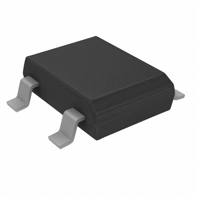
-
HDS10M-13
Diodes Incorporated
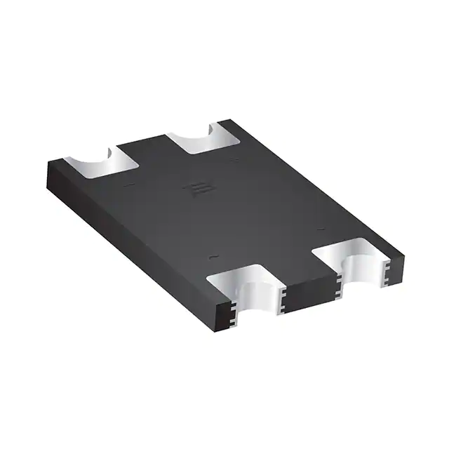
-
CD-MBL106S
Bourns Inc.
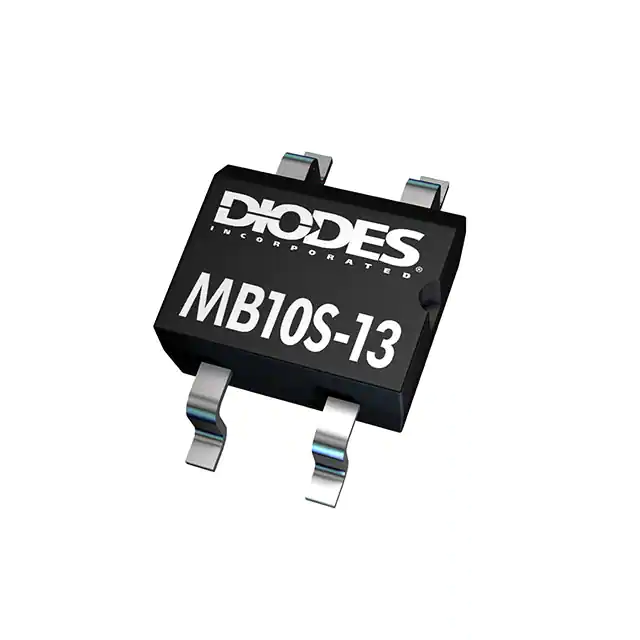
-
MB10S-13
Diodes Incorporated
-
CD-MBL206SL
Bourns Inc.
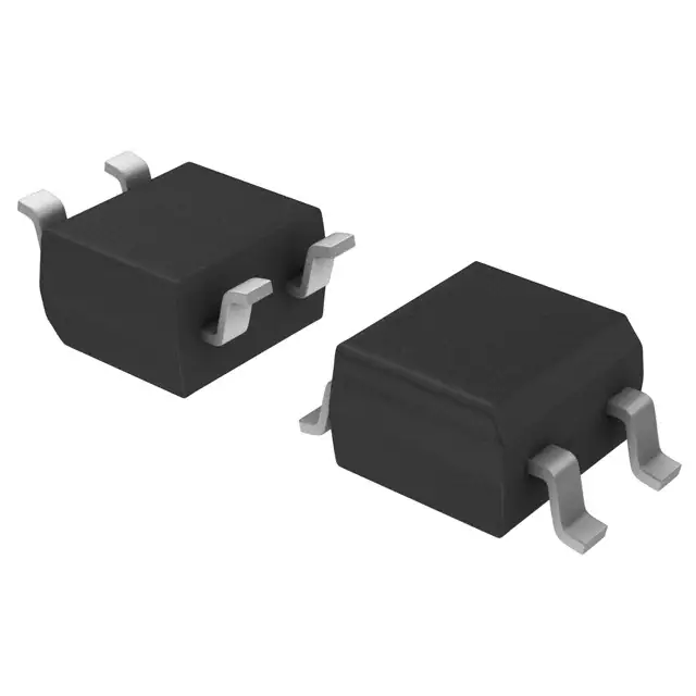
-
MB4S-TP
Micro Commercial Co
-
MB6S-TP
Micro Commercial Co
-
CD-MBL210S
Bourns Inc.
-
BAS3007ARPPE6327HTSA1
Infineon Technologies
-
DF02M
Diodes Incorporated
-
CD-MBL210SL
Bourns Inc.
-
DF04M
Diodes Incorporated
-
DF01M
Diodes Incorporated
Tech Hub

Counterfeit components can hide behind convincing markings and passing basic function tests. This engineering reference covers source traceability, external inspection, X-ray, XRF, electrical testing, …

A practical engineering and sourcing framework covering lifecycle verification, lifetime-buy calculations, replacement qualification, supplier checks and counterfeit-risk controls.

TTL and CMOS logic families differ in thresholds, loading, output drive, power and timing. This engineering guide compares 74HC and 74HCT, calculates noise margins and checks 3.3 V/5 V compatibility.

A practical engineering guide to 3.3V and 5V logic compatibility, input thresholds, resistor dividers, translator ICs, MOSFET level shifting, I2C pull-ups, timing limits and power-sequencing risks.

The 74HC595 uses push-pull logic outputs, while the TPIC6B595 uses 50 V open-drain DMOS sinks for higher-power loads. This guide compares timing, current limits, 3.3 V interfacing, load wiring, thermal…

The 74HC595 converts serial data into eight stable parallel outputs. This guide covers pin functions, shift and storage timing, OE and MR behavior, drive-current limits, cascading, voltage compatibilit…

A technical comparison of level-sensitive latches and edge-triggered flip-flops, covering timing windows, setup and hold limits, master–slave operation, time borrowing, race-through, HDL inference and…

A D latch stores one bit while Enable controls when data can pass. This reference covers gate-level operation, truth tables, transparency, setup and hold timing, LE versus OE, common ICs and practical …

An SR latch stores one bit through cross-coupled feedback. This engineering reference covers NOR and NAND implementations, truth tables, forbidden-state recovery, gated operation, switch debouncing, fa…

Latch circuits retain one bit through feedback. This technical reference covers SR and D latches, truth tables, transparency, timing limits, latch-versus-flip-flop behavior, applications and common log…


