
 My Inquiry
 My Account


Monolithic Power Systems Inc. HF81GS
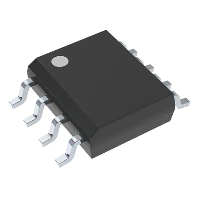
- Part No.:
- HF81GS
- Manufacturer:
- Monolithic Power Systems Inc.
- Category:
- Power Management - Specialized
- Package:
- 8-SOIC (0.154", 3.90mm Width)
- Datasheet:
-
 HF81GS.pdf
- Description:
- IC REG SWITCH CAP BLEED 8SOIC
- Quantity:
- Payment:

- Shipping:

Inventory:2,115
Please send an inquiry. Send us your inquiry, and we will respond immediately.
Product details
Overview
HF81GS from Monolithic Power Systems is a two-terminal X-capacitor bleeder IC that functions as a smart high-voltage switch in series with discharge resistors to eliminate standby power loss while ensuring automatic, safe X-capacitor discharge upon AC removal. It blocks current at 230 VAC (supply current ≤15 µA), activates discharge when AC is unplugged (detection time ≤25 ms), and integrates a 1000 V internal JFET for differential surge immunity. It is used in AC/DC front-ends requiring EuP Lot 6 and Energy Star V2.0 compliance.
For engineers reviewing the HF81GS datasheet, HF81GS pinout, HF81GS application, or HF81GS equivalent, key selection criteria include zero-crossing detection timing, 1000 V L1–L2 rating, dual-pin redundancy per terminal, creepage ≥4 mm, and compatibility with X-capacitors up to 5 µF and total series resistance down to 150 kΩ.
Technical Context
The HF81GS operates without external bias, deriving power directly from the AC line via internal charge-pump circuitry. Its core function relies on zero-crossing detection to reset an internal timer; absence of crossings for >25 ms triggers latch activation and discharge transistor turn-on.
It implements dual-pin redundancy per AC terminal (L1 and L2) to maintain safety integrity under single-point failure-open-circuit or short-circuit between opposite terminals results in benign behavior equivalent to omitting the device entirely. The 1000 V rated internal JFET and ≥4 mm creepage support IEC 60950-1 compliance in high-surge environments.
Key Specifications
| Parameter | Value and Actual Design Meaning |
|---|---|
| L1–L2 Voltage Rating | 1000 V - supports direct placement before or after input fuse in 265 VAC systems with margin for transients |
| AC Removal Detection Time | ≤25 ms - ensures X-cap discharge initiates within safety-compliant window after plug-out |
| Supply Current at 1000 V | 15 µA - enables ultra-low no-load consumption, critical for <30 mW standby targets |
| Saturation Current | 3.0 mA - guarantees reliable natural discharge across full input voltage range (110–410 V) |
| UVLO Threshold | 3.7 V - defines minimum L1/L2 voltage required to sustain internal operation and monitoring |
| Junction Temp Range | −40°C to +125°C - supports deployment in enclosed white-goods and telecom power enclosures |
| Thermal Resistance θJA | 90 °C/W - defines maximum continuous power dissipation (1.4 W at TA = 25°C) on standard 4-layer PCB |
Pinout & Package
HF81GS is housed in an SOIC-8 package with 1.27 mm pitch, JEDEC MS-012 AA compliant, featuring dual pins per AC terminal for redundancy and ≥4 mm creepage on PCB layout.
| Pin/Terminal | Circuit Role | Design Meaning |
|---|---|---|
| 1, 4, 5, 8 | NC | Not connected - no internal connection; must remain unconnected on PCB |
| 2, 3 | L1 | AC Line 1 input - dual-pin configuration provides fault tolerance against open-circuit failure |
| 6, 7 | L2 | AC Line 2 input - dual-pin configuration ensures continued discharge path if one pin fails open |
Key Features
| Feature | Design Value |
|---|---|
| No external bias required | Self-powered from AC line via integrated charge pump - eliminates auxiliary supply design complexity |
| Dual-pin per terminal | Two independent L1 and two independent L2 pins - maintains safety function under single-pin open or short-to-opposite-terminal failure |
| Zero-crossing based timing | Monitors AC zero crossings continuously; triggers discharge only after confirmed AC removal (>25 ms gap) - prevents false triggering during brownouts |
| High differential surge immunity | 1000 V internal JFET - withstands repetitive 1.5 kV+ surges without derating external MOVs |
| Creepage and clearance | ≥4 mm on package and recommended PCB layout - satisfies reinforced insulation requirements per IEC 60950-1 |
Applications
| Energy-Efficient Appliances | Server & Telecom Power Supplies |
|---|---|
Use Scenario: Dishwasher or air conditioner power supply with 2.5 µF X capacitor requiring <1 s discharge to 37% voltage per IEC 60950-1. IC Role / Device Role / Timing Role: Smart bleeder IC that disables discharge path during AC operation and enables it within 25 ms of plug-out. Use Value: Reduces standby power by eliminating 230 mW resistor loss while guaranteeing safety-compliant discharge timing. | Use Scenario: 1U server PSU with strict EuP Lot 6 and Energy Star V2.0 no-load power limits (<210 mW). IC Role / Device Role / Timing Role: High-voltage switch controlling bleed resistor network to achieve <30 mW no-load consumption. Use Value: Enables use of larger X capacitors for EMI filtering without compromising standby efficiency or safety certification. |
| ATX Desktop Power Supplies | Industrial AC/DC Converters |
Use Scenario: ATX v2.52-compliant PSU with X capacitor >0.1 µF placed before input fuse. IC Role / Device Role / Timing Role: Safety-critical bleeder positioned upstream of fuse to meet IEC 60950-1 discharge requirements. Use Value: Allows pre-fuse X-cap placement while maintaining functional safety under single-point failure conditions. | Use Scenario: Industrial motor drive front-end with 1.5 µF X capacitor and 1.5 kV surge requirement. IC Role / Device Role / Timing Role: Surge-tolerant bleeder placed adjacent to MOV on same PCB side to minimize loop inductance. Use Value: Maintains discharge functionality after repeated 1.5 kV surges due to 1000 V internal JFET and ≥4 mm creepage. |
Equivalent & Alternatives
The following parts are listed as comparable options for similar X-capacitor bleeder applications.
| Alternative Part | Technical Difference | Application Difference | Selection Advice |
|---|---|---|---|
| ST8002BTR | Three-terminal device requiring ground reference; 650 V rating; higher 25 µA supply current | Requires PCB ground plane access; unsuitable for floating or pre-fuse placement | Select when ground-referenced topology is fixed and 650 V margin suffices |
| ICE3B0565J | Integrated PWM controller with embedded bleeder function; not a dedicated bleeder; 650 V rating | Only usable when replacing entire controller IC; adds system-level complexity | Select only when redesigning control architecture and needing combined functions |
Compared with ST8002BTR and ICE3B0565J, HF81GS offers true two-terminal operation, 1000 V rating, and lowest supply current (15 µA), making it uniquely suited for pre-fuse, ground-free, ultra-low-power X-capacitor discharge in space-constrained AC/DC front-ends.
Availability
HF81GS is available at Aetrix Electronics and suitable for energy-efficient appliances, server power supplies, and industrial AC/DC converters requiring stable component supply, long-term lifecycle support, and safety-certified X-capacitor discharge functionality.
Supply support for HF81GS includes scheduled delivery planning, volume procurement assistance, BOM continuity management, traceable sourcing, and lifecycle availability coordination for OEM customers, industrial embedded developers, connected-device designers, and electronics production programs.
Manufacturer
Monolithic Power Systems (MPS) is a fabless semiconductor company specializing in high-performance analog and power ICs, with global design centers and manufacturing partnerships focused on energy efficiency and reliability.
The HF81GS belongs to MPS's safety and power management product line, engineered specifically for ultra-low-power, high-voltage AC/DC front-end applications where regulatory compliance, surge resilience, and no-load consumption are critical.
FAQ
What is the maximum X-capacitor value supported by HF81GS?
HF81GS supports X-capacitors up to 5 µF, as validated in Table 1 of the datasheet. At this value, a total series resistance of 150 kΩ achieves a 0.75 s RC time constant, ensuring discharge to 37% voltage within 1 second per IEC 60950-1, even with ±5% resistor and ±20% capacitor tolerances.
Can HF81GS be placed before the input fuse?
Yes - HF81GS is certified for use before or after the input fuse per IEC 60950-1. When the X capacitor exceeds 0.1 µF and is placed pre-fuse, HF81GS must also be positioned pre-fuse to satisfy safety discharge requirements, and the MOV should likewise be placed pre-fuse for surge levels >1.5 kV.
How does HF81GS handle single-point failures?
HF81GS uses dual pins for L1 (pins 2 & 3) and L2 (pins 6 & 7). If one pin opens, the other maintains continuity. If pins from opposite terminals short, the device behaves identically to a direct short - equivalent to removing HF81GS entirely - preserving system safety without introducing new hazards.
What is the role of the NC pins (1, 4, 5, 8)?
Pins 1, 4, 5, and 8 are internally not connected and must remain unconnected on the PCB. They serve no electrical function but provide mechanical symmetry and package compatibility. Routing traces or soldering to these pins may compromise creepage distance or thermal performance.
Does HF81GS require external timing components?
No - HF81GS contains fully integrated zero-crossing detection, timer, latch, and high-voltage switching circuitry. No external capacitors, resistors, or clock sources are needed. Its operation is self-contained and powered solely from the AC line across L1 and L2.
What is the significance of the 1000 V rating?
The 1000 V rating applies to the L1–L2 terminals and reflects the breakdown voltage of the internal JFET. It enables robust operation in 265 VAC systems with high transient margins, supports placement before MOVs, and eliminates need for external series voltage clamping in most 1.5 kV surge environments.
How does HF81GS reduce power loss compared to fixed resistors?
During AC operation, HF81GS blocks current through the external bleed resistors, reducing their power loss to zero. Only 15 µA quiescent current flows through the IC itself - cutting typical 100–400 mW resistor losses entirely, which directly enables compliance with EuP Lot 6 and Energy Star V2.0 standby power limits.
HF81GS Specifications
- Product attributes
- Attribute value
- Manufacturer:
- Monolithic Power Systems Inc.
- Series:
- -
- Package/Case:
- 8-SOIC (0.154", 3.90mm Width)
- Packaging:
- Tube
- Product Status:
- Active
- Applications:
- Home Appliance
- Current - Supply:
- 15µA
- Voltage - Supply:
- 85V ~ 265 VAC
- Operating Temperature:
- -40°C ~ 125°C
- Grade:
- -
- Qualification:
- -
- Mounting Type:
- Surface Mount
- Supplier Device Package:
- 8-SOIC
HF81GS FAQ
1.How can I place an order for HF81GS through Aetrix?
Please submit a Request for Quotation (RFQ) for HF81GS on Aetrix. Our sales agent will provide a competitive quotation and guide you through the order confirmation once you accept the terms.
2.Are the price and stock information for HF81GS reliable?
The price and inventory of HF81GS are updated periodically and may fluctuate due to market conditions. Stock and pricing data are typically refreshed every 24 hours. Quotation validity for HF81GS is usually 5 days.
3.What payment methods are accepted for HF81GS?
We accept Wire Transfer, PayPal, Credit Card, Western Union, MoneyGram, and Escrow for HF81GS transactions.
Note: Certain payment methods may incur a processing fee.
4.How is shipping managed for HF81GS?
HF81GS orders can be shipped via leading logistics carriers, including DHL, UPS, FedEx, TNT, or Registered Mail.
Once your HF81GS order is processed, you will receive an email with the shipment details and tracking number.
Note: Tracking information may take up to 24 hours to appear. Express delivery typically takes 3–5 business days.
5.How can I obtain technical support or documentation for HF81GS?
For technical support, including HF81GS datasheets, pinout diagrams, or application guidance, please contact our engineering support team. They can provide detailed documentation and assistance for your HF81GS requirements.
6.How does Aetrix verify that HF81GS is sourced from the original manufacturer or authorized distributors?
All HF81GS products on Aetrix are procured from qualified distributors and authorized channels. Our dedicated quality assurance team conducts strict verification, including traceability checks and, if necessary, third-party testing. This ensures that HF81GS meets industry standards.
7.What is the process for return or replacement of HF81GS?
All HF81GS units undergo pre-shipment inspection (PSI). If there is an issue with HF81GS, returns or replacements are accepted under the following conditions:
1.Quantity discrepancies, incorrect items, or visible external defects (such as breakage or corrosion), acknowledged by Aetrix.
2.The issue is reported within 90 days of delivery.
3.The HF81GS part is unused and in its original packaging.
Return procedure for HF81GS:
1.Submit a request within 90 days.
2.Obtain a Return Material Authorization (RMA) from Aetrix.
HF81GS Tags

-
TPS2511DGNR
Texas Instruments

-
UTC2000/MG
Microchip Technology

-
TUSB320HAIRWBR
Texas Instruments

-
TPS61252DSGR
Texas Instruments

-
PI5USB30216CXUAEX
Diodes Incorporated

-
SN6501DBVR
Texas Instruments

-
CYPD3177-24LQXQT
Infineon Technologies
-
SN6501QDBVRQ1
Texas Instruments

-
STUSB1600AQTR
STMicroelectronics

-
SN6505BDBVR
Texas Instruments
-
SN6501DBVT
Texas Instruments

-
TPS65150PWPR
Texas Instruments
Tech Hub

Operational amplifier guide covering op amp basics, feedback, ideal vs real op amps, common configurations, buffer circuits, offset, bias current, gain-bandwidth, slew rate, rail-to-rail limits and sel…

Jumper cables guide covering safe connection order, red and black clamp placement, final ground connection, cable gauge, length, clamp quality, copper vs CCA cables, jump starter comparison and battery…

LDO regulator guide covering low dropout voltage, power dissipation, thermal design, PSRR, output noise, capacitor stability, adjustable LDO circuits, LDO vs buck converter and datasheet selection chec…

Conditional Access Module guide covering CAM meaning, CI/CI+ interface, smart card authorization, DVB security workflow, TV and set-top box compatibility, internal electronics, ESD protection, connecto…

Guide to electronic component obsolescence covering EOL risk, PCN/PDN notices, last-time buy planning, replacement options, form-fit-function validation, counterfeit risk and BOM lifecycle management.

18650 battery guide covering lithium-ion cell basics, 3.6V/3.7V voltage, 4.2V charging, mAh and Wh capacity, protected cells, chargers, BMS, series-parallel packs, holders, welding and sourcing checks.…

Hall effect sensor guide covering working principle, linear and digital sensors, Arduino circuits, current sensing, speed detection, automotive applications, A3144 examples, signal filtering and datash…

Product Change Notification guide for electronic components, covering PCN meaning, PCN vs PDN/EOL, common change types, risk levels, form-fit-function review, engineering validation, BOM control, LTB/L…

A practical guide to blend door actuators, covering HVAC function, symptoms, location, AC and heater issues, reset and calibration, replacement cost, electrical diagnosis, compatibility checks, and rep…

Engineering guide to Raspberry Pi alternatives, covering chip-level differences, Orange Pi, ROCK, Jetson, Banana Pi, NanoPi, Compute Module, Pico, GPIO, camera, HAT compatibility, and replacement risks…


