
 My Inquiry
 My Account


Microchip Technology HV7361GA-G
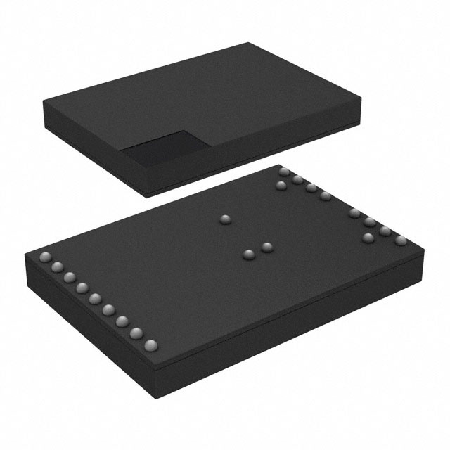
- Part No.:
- HV7361GA-G
- Manufacturer:
- Microchip Technology
- Category:
- Power Management - Specialized
- Package:
- 22-TFBGA
- Datasheet:
-
 HV7361GA-G.pdf
- Description:
- IC ULTRASOUND DRIVER 22CABGA
- Quantity:
- Payment:

- Shipping:

Inventory:110
Please send an inquiry. Send us your inquiry, and we will respond immediately.
Product details
Overview
HV7361GA-G from Microchip Technology is a high-voltage, high-speed ultrasound pulser IC integrating two-channel ±100V three-level transmit drivers with built-in fast return-to-zero (RTZ) damping FETs and an integrated two-terminal low-noise T/R switch. It delivers ±2.5A minimum pulse current per channel at up to 35 MHz, supports 2.5V/3.3V/5V CMOS logic interface, and is designed for medical ultrasound imaging systems requiring precise bipolar pulsing and receiver protection.
For engineers reviewing the HV7361GA-G datasheet, HV7361GA-G pinout, HV7361GA-G application, or HV7361GA-G equivalent, key selection considerations include its integrated T/R switch performance (±130V breakdown, 15Ω on-resistance, <20 ns switching), matched 2 ns delay times, AC-coupled gate drive architecture eliminating floating supplies, and CABGA-22 package compatibility with high-density transducer array layouts.
Technical Context
The HV7361GA-G implements dual independent high-voltage pulser channels, each comprising P-channel and N-channel MOSFETs with integrated RTZ damping control logic. Its AC-coupled gate driver topology eliminates need for floating bias rails while enabling ±100V output swing with minimal PCB layout complexity.
It integrates a dedicated two-terminal T/R switch that routes transducer signals between transmit and receive paths, featuring ±130V breakdown voltage, 15Ω on-resistance, ±60 mA peak switching current, and sub-20 ns turn-on/turn-off times - all specified under 50Ω load and 100 MHz small-signal bandwidth.
Key Specifications
| Parameter | Value and Actual Design Meaning |
|---|---|
| Output Voltage Range | 0 V to ±100 V - enables full-scale bipolar excitation of piezoelectric transducers without external level-shifting circuitry |
| Pulse Current Capability | ±2.5 A minimum per channel - sufficient to drive low-impedance transducer loads in high-resolution medical imaging |
| Operating Frequency | Up to 35 MHz - supports high-frequency ultrasound modes including harmonic imaging and elastography |
| Delay Matching | 2 ns matched delay times (channel-to-channel) - ensures precise timing alignment critical for beamforming accuracy |
| T/R Switch On-Resistance | 15 Ω typical - minimizes signal attenuation and insertion loss between transducer and LNA during receive mode |
| Logic Interface Voltage | 2.5 V / 3.3 V / 5 V CMOS compatible - allows direct interfacing with FPGA or ASIC controller I/O banks without level translation |
| Package Type | 22-ball CABGA (5 mm × 7 mm) - compact footprint optimized for multi-channel probe PCB stacking and thermal management |
Pinout & Package
Package: 22-ball Chip Array Ball Grid Array (CABGA), 5 mm × 7 mm body, 0.5 mm pitch, RoHS-compliant lead-free finish.
| Pin/Terminal | Circuit Role | Design Meaning |
|---|---|---|
| GND | Driver ground reference | Common return path for logic, level translator, and gate drive circuits; must connect to low-impedance system ground plane |
| VDD, VH, VSS, VL1–VL3 | Power supply terminals | VDD/VH = +10 V gate drive high-side; VSS/VL1–VL3 = 0 V gate drive low-side; decoupling required between VH and VL3 (0.22 µF) |
| INA, INB, INC, IND | CMOS logic inputs | Control P-FET1/N-FET1 (INA/INB) and P-FET2/N-FET2 (INC/IND); support 2.5–5 V logic levels with ≤1 µA input current |
| PE | Power enable input | Active-high enable (1.7–5.25 V) controlling global device power state; defines safe power-up/down sequencing |
| SP1, DP1, DN1, SN1 SP2, DP2, DN2, SN2 |
High-voltage output terminals | Source/drain connections for dual-channel P/N-FET pairs; SPx/SNx supply ±100 V; DPx/DNx deliver pulsed outputs to transducer |
| XDCR, RX | T/R switch terminals | XDCR = transducer node; RX = receiver LNA input; internal switch connects them only during receive mode (PE active, logic idle) |
Key Features
| Feature | Design Value |
|---|---|
| Integrated T/R switch | Two-terminal architecture with ±130 V breakdown, 15 Ω RSW, and <20 ns switching - eliminates discrete diode/T/R module, reduces BOM count and parasitic capacitance |
| AC-coupled gate drive | Removes need for floating ±100 V bias rails and associated decoupling capacitors - simplifies power supply design and improves layout reliability |
| Matched propagation delay | ±2 ns device-to-device and 2 ns channel-to-channel matching - enables coherent multi-channel beam synthesis without external calibration |
| Low quiescent current | 50 µA VDD current (PE = 0), 1 mA (PE = 1) - extends battery life in portable ultrasound handheld systems |
| Robust thermal design | θJA = 106 °C/W in CABGA-22 package - supports continuous operation at TA = –40°C to +85°C with standard PCB copper pour |
Applications
| Medical Ultrasound Imaging | Piezoelectric Transducer Drivers |
|---|---|
Use Scenario: High-resolution B-mode and Doppler imaging in portable and cart-based diagnostic systems. IC Role / Device Role / Timing Role: Dual-channel three-level pulser generating precisely timed ±100 V, ±2.5 A excitation bursts synchronized to echo acquisition windows. Use Value: Integrated T/R switch protects sensitive LNA inputs from high-voltage transmit pulses while minimizing signal path discontinuity during receive. |
Use Scenario: Driving low-impedance (<50 Ω), high-capacitance (>1 nF) piezoceramic elements in therapeutic ultrasound and focused ultrasound surgery (FUS). IC Role / Device Role / Timing Role: High-current, high-slew-rate pulser delivering controlled bipolar waveforms with sub-10 ns rise/fall times and matched delays. Use Value: AC-coupled architecture eliminates floating supplies, reducing system cost and improving long-term reliability in sealed transducer housings. |
| Ultrasound Industrial NDT | Pulse Waveform Generator |
Use Scenario: Non-destructive testing of composite materials, welds, and castings using phased-array probes. IC Role / Device Role / Timing Role: Multi-channel transmit driver enabling electronic beam steering and focusing via time-delayed pulsing across 16–64 elements. Use Value: 35 MHz operating frequency and 2 ns delay matching support high-frequency inspection (>10 MHz) with sub-millimeter resolution. |
Use Scenario: Programmable arbitrary waveform generation for research-grade acoustic characterization and material property analysis. IC Role / Device Role / Timing Role: Precision high-voltage pulse source with configurable logic-controlled output states (positive, negative, zero) and RTZ damping. Use Value: Built-in damping FETs suppress ringing after pulse termination, ensuring clean waveform edges and accurate time-of-flight measurements. |
Equivalent & Alternatives
The following parts are listed as comparable options for similar high-voltage ultrasound pulser applications.
| Alternative Part | Technical Difference | Application Difference | Selection Advice |
|---|---|---|---|
| HV7360GA-G | No integrated T/R switch; identical pulser core, pinout, and electrical specs except missing XDCR/RX terminals | Suitable only when external T/R switching (e.g., diode-based or discrete FET) is implemented separately | Select HV7360GA-G if system already includes robust external T/R protection and board space is constrained |
| QSC7361 (Qorvo) | Same 22-pin CABGA footprint and ±100 V/±2.5 A rating but uses different logic mapping and lacks PE enable; higher 3.5 mA IDDQ | Requires redesign of control interface and power sequencing; no integrated T/R switch | Consider QSC7361 only for drop-in replacement where existing firmware supports alternate timing and no T/R integration is needed |
Compared with HV7360GA-G, HV7361GA-G adds essential T/R functionality without increasing board area or power supply complexity; versus QSC7361, it offers superior integration, lower quiescent current, and guaranteed timing matching - making it optimal for new medical and industrial ultrasound designs requiring compact, reliable transmit/receive switching.
Availability
HV7361GA-G is available at Aetrix Electronics and suitable for medical ultrasound imaging systems, industrial NDT equipment, and piezoelectric transducer driver modules requiring stable component supply, long-lifecycle support, and RoHS-compliant packaging.
Supply support for HV7361GA-G includes scheduled delivery planning, volume procurement assistance, BOM continuity management, traceable sourcing, and lifecycle availability coordination for OEM customers, industrial embedded developers, connected-device designers, and electronics production programs.
Manufacturer
Microchip Technology is a global provider of microcontrollers, analog, FPGA, and connectivity solutions, with deep expertise in high-reliability mixed-signal ICs for medical, automotive, and industrial markets.
HV7361GA-G belongs to Microchip's high-voltage ultrasound pulser family, engineered specifically for portable and high-channel-count ultrasound systems needing integrated T/R switching, low-power operation, and precision timing control.
FAQ
What is the maximum operating frequency supported by HV7361GA-G?
HV7361GA-G supports operation up to 35 MHz, verified under load conditions of CLOAD = 330 pF and RLOAD = 2.5 kΩ. This frequency capability enables use in high-resolution ultrasound imaging, including harmonic and contrast-enhanced modes, while maintaining <10 ns rise/fall times and tight channel-to-channel delay matching.
Does HV7361GA-G require external floating power supplies for its high-voltage outputs?
No, HV7361GA-G uses an AC-coupled gate driver architecture that eliminates the need for floating ±100 V bias rails. The device operates from single-ended VH (+10 V) and VSS (0 V) supplies, significantly simplifying power design and reducing component count compared to traditional DC-coupled pulsers.
How does the integrated T/R switch in HV7361GA-G protect the receiver front-end?
The HV7361GA-G T/R switch provides ±130 V breakdown voltage and isolates the LNA input (RX) from transducer (XDCR) during transmit, limiting leakage to ±300 µA at ±130 V. With 15 Ω on-resistance and <20 ns switching, it ensures minimal signal loss and fast transition into low-noise receive mode.
What is the recommended power-up sequence for HV7361GA-G?
The recommended power-up sequence for HV7361GA-G is: (1) apply VLL (logic supply), (2) apply VDD, VH, VSS, and VL with logic inputs low, (3) apply ±100 V high-voltage supplies (VPP/VNN), then (4) assert PE high. This sequence minimizes inrush current and ensures proper initialization of internal level translators and gate drivers.
Is HV7361GA-G pin-compatible with HV7360GA-G?
HV7361GA-G is not fully pin-compatible with HV7360GA-G: while both share identical 22-ball CABGA footprint and 19 common signal/power pins, HV7361GA-G replaces two NC pads (G4 and P5) with XDCR and RX terminals for its integrated T/R switch - requiring PCB layout revision for migration.
HV7361GA-G Specifications
- Product attributes
- Attribute value
- Manufacturer:
- Microchip Technology
- Series:
- -
- Package/Case:
- 22-TFBGA
- Packaging:
- Tray
- Product Status:
- Active
- Applications:
- Pulse Generator
- Current - Supply:
- 50µA
- Voltage - Supply:
- 4.75V ~ 11V
- Operating Temperature:
- -20°C ~ 85°C
- Grade:
- -
- Qualification:
- -
- Mounting Type:
- Surface Mount
- Supplier Device Package:
- 22-CABGA (5x7)
HV7361GA-G FAQ
1.How can I place an order for HV7361GA-G through Aetrix?
Please submit a Request for Quotation (RFQ) for HV7361GA-G on Aetrix. Our sales agent will provide a competitive quotation and guide you through the order confirmation once you accept the terms.
2.Are the price and stock information for HV7361GA-G reliable?
The price and inventory of HV7361GA-G are updated periodically and may fluctuate due to market conditions. Stock and pricing data are typically refreshed every 24 hours. Quotation validity for HV7361GA-G is usually 5 days.
3.What payment methods are accepted for HV7361GA-G?
We accept Wire Transfer, PayPal, Credit Card, Western Union, MoneyGram, and Escrow for HV7361GA-G transactions.
Note: Certain payment methods may incur a processing fee.
4.How is shipping managed for HV7361GA-G?
HV7361GA-G orders can be shipped via leading logistics carriers, including DHL, UPS, FedEx, TNT, or Registered Mail.
Once your HV7361GA-G order is processed, you will receive an email with the shipment details and tracking number.
Note: Tracking information may take up to 24 hours to appear. Express delivery typically takes 3–5 business days.
5.How can I obtain technical support or documentation for HV7361GA-G?
For technical support, including HV7361GA-G datasheets, pinout diagrams, or application guidance, please contact our engineering support team. They can provide detailed documentation and assistance for your HV7361GA-G requirements.
6.How does Aetrix verify that HV7361GA-G is sourced from the original manufacturer or authorized distributors?
All HV7361GA-G products on Aetrix are procured from qualified distributors and authorized channels. Our dedicated quality assurance team conducts strict verification, including traceability checks and, if necessary, third-party testing. This ensures that HV7361GA-G meets industry standards.
7.What is the process for return or replacement of HV7361GA-G?
All HV7361GA-G units undergo pre-shipment inspection (PSI). If there is an issue with HV7361GA-G, returns or replacements are accepted under the following conditions:
1.Quantity discrepancies, incorrect items, or visible external defects (such as breakage or corrosion), acknowledged by Aetrix.
2.The issue is reported within 90 days of delivery.
3.The HV7361GA-G part is unused and in its original packaging.
Return procedure for HV7361GA-G:
1.Submit a request within 90 days.
2.Obtain a Return Material Authorization (RMA) from Aetrix.
HV7361GA-G Tags

-
TPS2511DGNR
Texas Instruments

-
UTC2000/MG
Microchip Technology

-
TUSB320HAIRWBR
Texas Instruments

-
TPS61252DSGR
Texas Instruments

-
PI5USB30216CXUAEX
Diodes Incorporated

-
SN6501DBVR
Texas Instruments

-
CYPD3177-24LQXQT
Infineon Technologies
-
SN6501QDBVRQ1
Texas Instruments

-
STUSB1600AQTR
STMicroelectronics

-
SN6505BDBVR
Texas Instruments
-
SN6501DBVT
Texas Instruments

-
TPS65150PWPR
Texas Instruments
Tech Hub

TTL and CMOS logic families differ in thresholds, loading, output drive, power and timing. This engineering guide compares 74HC and 74HCT, calculates noise margins and checks 3.3 V/5 V compatibility.

A practical engineering guide to 3.3V and 5V logic compatibility, input thresholds, resistor dividers, translator ICs, MOSFET level shifting, I2C pull-ups, timing limits and power-sequencing risks.

The 74HC595 uses push-pull logic outputs, while the TPIC6B595 uses 50 V open-drain DMOS sinks for higher-power loads. This guide compares timing, current limits, 3.3 V interfacing, load wiring, thermal…

The 74HC595 converts serial data into eight stable parallel outputs. This guide covers pin functions, shift and storage timing, OE and MR behavior, drive-current limits, cascading, voltage compatibilit…

A technical comparison of level-sensitive latches and edge-triggered flip-flops, covering timing windows, setup and hold limits, master–slave operation, time borrowing, race-through, HDL inference and…

A D latch stores one bit while Enable controls when data can pass. This reference covers gate-level operation, truth tables, transparency, setup and hold timing, LE versus OE, common ICs and practical …

An SR latch stores one bit through cross-coupled feedback. This engineering reference covers NOR and NAND implementations, truth tables, forbidden-state recovery, gated operation, switch debouncing, fa…

Latch circuits retain one bit through feedback. This technical reference covers SR and D latches, truth tables, transparency, timing limits, latch-versus-flip-flop behavior, applications and common log…

An engineering guide to LED driver operation, constant-current and constant-voltage outputs, linear and switching topologies, dimming, IC selection, calculations, replacement compatibility, and fault c…

Operational amplifier guide covering op amp basics, feedback, ideal vs real op amps, common configurations, buffer circuits, offset, bias current, gain-bandwidth, slew rate, rail-to-rail limits and sel…


