
 My Inquiry
 My Account


Infineon Technologies IFCM10S60GDXKMA1
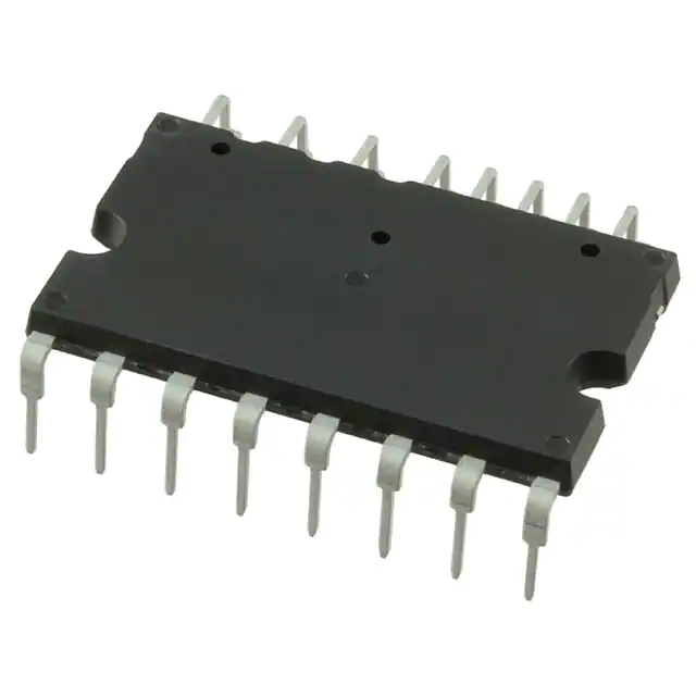
- Part No.:
- IFCM10S60GDXKMA1
- Manufacturer:
- Infineon Technologies
- Category:
- Power Driver Modules
- Package:
- 24-PowerDIP Module (1.028", 26.10mm)
- Datasheet:
-
 IFCM10S60GDXKMA1.pdf
- Description:
- IFPS MODULES
- Quantity:
- Payment:

- Shipping:

Inventory:280
Please send an inquiry. Send us your inquiry, and we will respond immediately.
Product details
Overview
IFCM10S60GDXKMA1 from Infineon Technologies is a dual-in-line intelligent power module integrating a 3-phase 600 V / 10 A inverter bridge and a single-phase 650 V / 30 A PFC stage, featuring TRENCHSTOP™ IGBT3 devices, SOI gate drivers, integrated bootstrap, overcurrent shutdown (ITRIP threshold = 0.47 V), and NTC-based temperature monitoring. It targets variable-speed motor drives in home appliances requiring compact, thermally robust, EMI-optimized power conversion.
For engineers reviewing the IFCM10S60GDXKMA1 datasheet, IFCM10S60GDXKMA1 pinout, IFCM10S60GDXKMA1 application, or IFCM10S60GDXKMA1 equivalent, key selection criteria include its dual-section topology (inverter + PFC), 600 V/10 A inverter rating, 450 V DC-link limit, fault signaling via VFO, and high-side floating supply architecture with VS pin tolerance to −50 V transients.
Technical Context
The module implements a fully integrated 3-phase inverter using six TRENCHSTOP™ IGBT3 switches with anti-parallel diodes, driven by a rugged SOI-based gate driver with cross-conduction prevention and 380 ns minimum deadtime. Its control section supports 3.3 V–15 V logic inputs with Schmitt-trigger noise filtering (tFILIN ≥ 1 µs) and internal 5 kΩ pull-downs.
The integrated single-phase boost PFC stage uses a dedicated TRENCHSTOP™ IGBT3 and rapid-switching emitter-controlled diode, controlled via GX/NX/X pins. Thermal protection is implemented via an on-module NTC referenced to VSS and accessible at VFO, while overcurrent detection uses a dedicated comparator (VITRIP = 0.47 V) with 530 ns noise immunity.
Key Specifications
| Parameter | Value and Actual Design Meaning |
|---|---|
| Inverter Voltage Rating | 600 V VCES; supports DC-link up to 450 V continuous, 500 V surge - defines maximum bus voltage for motor drive stage. |
| Inverter Current Rating | 10 A continuous IC at TC = 25°C; enables compact 1–1.5 kW motor drives without external heatsink oversizing. |
| PFC Voltage Rating | 650 V VCES; supports single-phase boost PFC operation up to 450 V DC output - matches inverter bus voltage. |
| Overcurrent Threshold | 0.47 V at ITRIP pin; provides precise current sensing interface for shunt-based motor phase current monitoring. |
| Floating Supply Tolerance | VS(U/V/W) withstands −50 V transient vs. VSS; ensures reliable high-side gate driving under fast switching-induced negative spikes. |
| Thermal Monitoring | Integrated NTC referenced to VSS; enables direct microcontroller ADC reading of module case temperature via VFO pin with external 5 V pull-up. |
| Logic Compatibility | HIN/LIN inputs accept 3.3 V–15 V CMOS/LSTTL; eliminates level-shifter requirement for modern MCU interfaces. |
Pinout & Package
Dual-in-line molded package with 24-pin through-hole footprint (package outline per Infineon Doc. No. Q67200-C2911-1); features DCB substrate for low thermal resistance and creepage/clearance optimized for 2000 VRMS isolation.
| Pin/Terminal | Circuit Role | Design Meaning |
|---|---|---|
| 1–6 (VS/U,V,W; VB/U,V,W) | High-side floating supply references and voltages | Enable self-contained bootstrap operation; VS pins tolerate −50 V transients relative to VSS - critical for noise immunity in high-dv/dt motor drives. |
| 7–12 (HIN/LIN U,V,W) | Gate driver logic inputs | Positive-logic, Schmitt-triggered inputs with 5 kΩ internal pull-downs and 1 µs minimum pulse width requirement - prevent spurious turn-on during startup or noise events. |
| 13 (VDD), 16 (VSS) | Low-side control supply rails | VDD powers input logic and low-side drivers; UVLO thresholds (12.1 V / 10.4 V) ensure safe gate drive voltage margins during brownout conditions. |
| 14 (VFO) | Fault output & NTC node | Open-drain fault signal (latched UV/OCP) and analog NTC output - allows single-pin dual-function thermal and fault monitoring with external 5 V pull-up. |
| 15 (ITRIP) | Overcurrent detection input | Comparator input referenced to VSS with 0.47 V threshold and 530 ns noise filter - interfaces directly to shunt amplifier outputs. |
| 17 (N) | Low-side emitter common | Provides Kelvin connection point for current sensing; must be routed short-to-VSS to minimize inductive offset errors in shunt measurements. |
| 18–20 (W,V,U) | Motor phase outputs | Bridge outputs connecting to motor windings; electrically isolated from control logic - require proper PCB layout for EMI suppression. |
| 21 (P) | Positive DC bus input | Common anode node for inverter high-side IGBTs and PFC diode; rated for ≤450 V DC - defines system-level bus voltage limit. |
| 22–24 (X,NX,GX) | PFC IGBT collector/emitter/gate | Enable standalone boost PFC stage integration; X connects to PFC diode anode, NX to AC input rectifier, GX to PWM controller - decouples PFC timing from inverter control. |
Key Features
| Feature | Design Value |
|---|---|
| Integrated PFC + Inverter | Single-package solution combining 650 V PFC IGBT and 600 V 3-phase inverter - reduces BOM count, PCB area, and interconnect losses in HVAC and appliance inverters. |
| Rugged SOI Gate Driver | Immune to transient negative VS potentials (−50 V) and dv/dt-induced false triggering - eliminates need for external gate clamping or complex bootstrap design. |
| Cross-Conduction Prevention | Hardware-enforced deadtime (380 ns typical) and shoot-through lockout - guarantees safe commutation without software timing dependency. |
| Unified Fault Signaling | VFO pin reports both under-voltage (VDD < 10.4 V) and overcurrent (ITRIP active) as open-drain latch - simplifies system-level fault handling with one interrupt input. |
| Thermal Monitoring Interface | On-module NTC accessible via VFO with standard 5 V pull-up - enables real-time junction temperature estimation without external sensor routing. |
Applications
| Refrigerator Compressor Drive | Air Conditioner Indoor Fan |
|---|---|
Use Scenario: Variable-speed BLDC compressor control with integrated PFC to meet IEC 61000-3-2 harmonic limits. IC Role / Device Role / Timing Role: CIPOS™ module executes both PFC regulation (via GX/NX/X) and 3-phase motor commutation (via HIN/LIN), synchronized by MCU PWM timers. Use Value: Eliminates discrete PFC controller and separate inverter gate drivers - reduces component count by >12 parts and PCB area by 35% versus discrete implementation. | Use Scenario: Low-noise, high-efficiency indoor fan motor drive in split-system AC units. IC Role / Device Role / Timing Role: Provides isolated high-side gate drive and current-sense feedback (via N and ITRIP) for field-oriented control (FOC) loop execution. Use Value: Integrated bootstrap and −50 V VS tolerance enable stable operation at 20 kHz switching without external charge pumps or level shifters. |
| Washing Machine Drum Motor | Dishwasher Circulation Pump |
Use Scenario: High-torque, start-stop duty cycle motor control with overload protection and thermal derating. IC Role / Device Role / Timing Role: Delivers peak 20 A output current (≤1 ms) and monitors case temperature via VFO/NTC to dynamically adjust torque profile. Use Value: On-chip overcurrent and thermal fault latching prevents IGBT destruction during mechanical jam - improves field reliability without external protection ICs. | Use Scenario: Compact, sealed circulation pump requiring high IP rating and minimal EMI emissions. IC Role / Device Role / Timing Role: Integrates EMI-optimized gate drive, DCB thermal path, and creepage-enhanced packaging - meets EN 55014-1 Class B conducted emission limits. Use Value: Dual-in-line package with 1.6 mm pin-to-heatsink clearance enables conformal coating and direct mounting to metal chassis - simplifies IP67 mechanical design. |
Equivalent & Alternatives
The following parts are listed as comparable options for similar intelligent power module applications.
| Alternative Part | Technical Difference | Application Difference | Selection Advice |
|---|---|---|---|
| FSA60065A | 650 V / 6 A inverter-only IPM; no integrated PFC stage; requires external PFC controller and gate drivers. | Suitable only for systems where PFC is handled separately (e.g., multi-board designs); lacks VFO/NTC integration. | Select when cost sensitivity outweighs integration benefit and board space permits discrete PFC implementation. |
| FSBB10CH60C | 600 V / 10 A inverter-only IPM; includes built-in bootstrap diodes but no PFC section or NTC; uses different pinout and logic thresholds. | Requires external PFC stage and separate temperature sensing; not pin-compatible with IFCM10S60GDXKMA1. | Choose for legacy designs migrating from FSBB series where PFC is already implemented externally. |
Compared with FSA60065A and FSBB10CH60C, IFCM10S60GDXKMA1 uniquely integrates PFC and inverter in one package with unified fault reporting and thermal monitoring - reducing system complexity and improving reliability in space-constrained home appliance inverters.
Availability
IFCM10S60GDXKMA1 is available at Aetrix Electronics and suitable for refrigerator compressor drives, air conditioner indoor fans, and washing machine drum motor controls requiring stable component supply, long-lifecycle support, and RoHS-compliant manufacturing.
Supply support for IFCM10S60GDXKMA1 includes scheduled delivery planning, volume procurement assistance, BOM continuity management, traceable sourcing, and lifecycle availability coordination for OEM customers, industrial embedded developers, connected-device designers, and electronics production programs.
Manufacturer
Infineon Technologies AG is a German semiconductor manufacturer specializing in power management, automotive, and industrial control ICs, with leadership in IGBT, SiC, and intelligent power modules.
The CIPOS™ product line delivers integrated power stages for variable-speed motor drives, combining gate drivers, protection logic, and power semiconductors to simplify inverter design for home appliance and HVAC applications.
FAQ
What is the maximum allowable DC-link voltage for IFCM10S60GDXKMA1?
The absolute maximum DC-link voltage between P and N is 450 V continuous and 500 V for surge conditions. Exceeding 450 V risks permanent damage to the inverter IGBTs and PFC diode. This rating is defined in the Absolute Maximum Ratings table (page 7 of datasheet Rev. 2.2) and must be respected even during transient events.
How is thermal protection implemented in this module?
Thermal protection uses an integrated NTC thermistor referenced to VSS and accessed via the VFO pin. With a 5 V external pull-up resistor, the resulting analog voltage scales linearly with temperature and can be read by a microcontroller ADC. The same pin also serves as open-drain fault output for UVLO and overcurrent events.
Can the PFC and inverter sections operate independently?
Yes - the PFC stage (controlled via GX/NX/X pins) and inverter stage (controlled via HIN/LIN pins) have independent gate drive paths, power supplies, and protection circuits. They share only the P and N terminals for DC-bus connection, allowing asynchronous or coordinated control depending on system architecture requirements.
What is the purpose of the VS pins and their −50 V rating?
The VS(U/V/W) pins serve as high-side floating supply references for the SOI gate drivers. Their −50 V transient tolerance (relative to VSS) ensures reliable operation during fast switching transitions where negative voltage spikes occur on the high-side emitter nodes - preventing false turn-off or latch-up in noisy motor drive environments.
IFCM10S60GDXKMA1 Specifications
- Product attributes
- Attribute value
- Manufacturer:
- Infineon Technologies
- Series:
- CIPOS™
- Package/Case:
- 24-PowerDIP Module (1.028", 26.10mm)
- Packaging:
- Tube
- Product Status:
- Active
- Type:
- IGBT
- Configuration:
- 3 Phase Inverter
- Current:
- 30 A
- Voltage:
- 650 V
- Voltage - Isolation:
- 2000Vrms
- Grade:
- -
- Qualification:
- -
- Mounting Type:
- Through Hole
IFCM10S60GDXKMA1 FAQ
1.How can I place an order for IFCM10S60GDXKMA1 through Aetrix?
Please submit a Request for Quotation (RFQ) for IFCM10S60GDXKMA1 on Aetrix. Our sales agent will provide a competitive quotation and guide you through the order confirmation once you accept the terms.
2.Are the price and stock information for IFCM10S60GDXKMA1 reliable?
The price and inventory of IFCM10S60GDXKMA1 are updated periodically and may fluctuate due to market conditions. Stock and pricing data are typically refreshed every 24 hours. Quotation validity for IFCM10S60GDXKMA1 is usually 5 days.
3.What payment methods are accepted for IFCM10S60GDXKMA1?
We accept Wire Transfer, PayPal, Credit Card, Western Union, MoneyGram, and Escrow for IFCM10S60GDXKMA1 transactions.
Note: Certain payment methods may incur a processing fee.
4.How is shipping managed for IFCM10S60GDXKMA1?
IFCM10S60GDXKMA1 orders can be shipped via leading logistics carriers, including DHL, UPS, FedEx, TNT, or Registered Mail.
Once your IFCM10S60GDXKMA1 order is processed, you will receive an email with the shipment details and tracking number.
Note: Tracking information may take up to 24 hours to appear. Express delivery typically takes 3–5 business days.
5.How can I obtain technical support or documentation for IFCM10S60GDXKMA1?
For technical support, including IFCM10S60GDXKMA1 datasheets, pinout diagrams, or application guidance, please contact our engineering support team. They can provide detailed documentation and assistance for your IFCM10S60GDXKMA1 requirements.
6.How does Aetrix verify that IFCM10S60GDXKMA1 is sourced from the original manufacturer or authorized distributors?
All IFCM10S60GDXKMA1 products on Aetrix are procured from qualified distributors and authorized channels. Our dedicated quality assurance team conducts strict verification, including traceability checks and, if necessary, third-party testing. This ensures that IFCM10S60GDXKMA1 meets industry standards.
7.What is the process for return or replacement of IFCM10S60GDXKMA1?
All IFCM10S60GDXKMA1 units undergo pre-shipment inspection (PSI). If there is an issue with IFCM10S60GDXKMA1, returns or replacements are accepted under the following conditions:
1.Quantity discrepancies, incorrect items, or visible external defects (such as breakage or corrosion), acknowledged by Aetrix.
2.The issue is reported within 90 days of delivery.
3.The IFCM10S60GDXKMA1 part is unused and in its original packaging.
Return procedure for IFCM10S60GDXKMA1:
1.Submit a request within 90 days.
2.Obtain a Return Material Authorization (RMA) from Aetrix.
IFCM10S60GDXKMA1 Tags
-
IGCM15F60GAXKMA1
Infineon Technologies
-
FSBB30CH60C
onsemi

-
LMG3522R030RQSR
Texas Instruments
-
LMG3522R030QRQSTQ1
Texas Instruments
-
IM828XCCXKMA1
Infineon Technologies
-
2SP0430T2A0C-FF1800R17IP5
Power Integrations
.jpg)
-
FBS-GAM02-P-C50
EPC Space, LLC
-
AOZ5507QI_2
Alpha & Omega Semiconductor Inc.
-
AOZ5517QI_2
Alpha & Omega Semiconductor Inc.
-
NV6117-RA
Navitas Semiconductor, Inc.
-
FDMF5062
onsemi
-
NV6127
Navitas Semiconductor, Inc.
Tech Hub

An SR latch stores one bit through cross-coupled feedback. This engineering reference covers NOR and NAND implementations, truth tables, forbidden-state recovery, gated operation, switch debouncing, fa…

Latch circuits retain one bit through feedback. This technical reference covers SR and D latches, truth tables, transparency, timing limits, latch-versus-flip-flop behavior, applications and common log…

An engineering guide to LED driver operation, constant-current and constant-voltage outputs, linear and switching topologies, dimming, IC selection, calculations, replacement compatibility, and fault c…

Operational amplifier guide covering op amp basics, feedback, ideal vs real op amps, common configurations, buffer circuits, offset, bias current, gain-bandwidth, slew rate, rail-to-rail limits and sel…

Jumper cables guide covering safe connection order, red and black clamp placement, final ground connection, cable gauge, length, clamp quality, copper vs CCA cables, jump starter comparison and battery…

LDO regulator guide covering low dropout voltage, power dissipation, thermal design, PSRR, output noise, capacitor stability, adjustable LDO circuits, LDO vs buck converter and datasheet selection chec…

Conditional Access Module guide covering CAM meaning, CI/CI+ interface, smart card authorization, DVB security workflow, TV and set-top box compatibility, internal electronics, ESD protection, connecto…

Guide to electronic component obsolescence covering EOL risk, PCN/PDN notices, last-time buy planning, replacement options, form-fit-function validation, counterfeit risk and BOM lifecycle management.

18650 battery guide covering lithium-ion cell basics, 3.6V/3.7V voltage, 4.2V charging, mAh and Wh capacity, protected cells, chargers, BMS, series-parallel packs, holders, welding and sourcing checks.…

Hall effect sensor guide covering working principle, linear and digital sensors, Arduino circuits, current sensing, speed detection, automotive applications, A3144 examples, signal filtering and datash…


