
 My Inquiry
 My Account


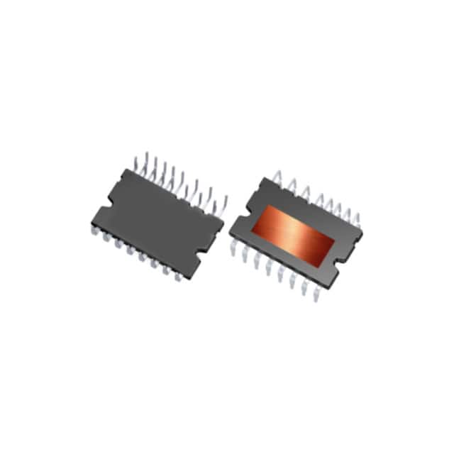
Infineon Technologies IM828XCCXKMA1
- Part No.:
- IM828XCCXKMA1
- Manufacturer:
- Infineon Technologies
- Category:
- Power Driver Modules
- Package:
- 24-PowerDIP Module (1.094", 27.80mm)
- Datasheet:
-
 IM828XCCXKMA1.pdf
- Description:
- CIPOS MAXI 1200V 35A PG-MDIP-24
- Quantity:
- Payment:

- Shipping:

Inventory:235
Please send an inquiry. Send us your inquiry, and we will respond immediately.
Product details
Overview
IM828XCCXKMA1 from Infineon Technologies is a fully isolated three-phase CIPOS™ Maxi intelligent power module integrating six 1200V CoolSiC™ MOSFETs and an optimized 6-channel SOI gate driver. It serves as a high-performance inverter for industrial motor drives and active power factor correction, delivering ±35 A continuous phase current at TC = 25°C, 900 V DC-link voltage capability, and integrated NTC thermistor for thermal monitoring.
For engineers reviewing the IM828XCCXKMA1 datasheet, IM828XCCXKMA1 pinout, IM828XCCXKMA1 application, or IM828XCCXKMA1 equivalent, key selection considerations include its 1200V SiC MOSFET blocking rating, -11 V allowable negative VS potential under VBS = 15 V, programmable fault-clear timing via RFE pin, open-source low-side source pins (NU/NV/NW) for phase current sensing, and built-in anti-cross-conduction logic with 300 ns minimum deadtime.
Technical Context
The IM828XCCXKMA1 implements a three-phase inverter topology with independent high- and low-side gate drivers per phase, using SOI-based isolation to sustain ±1200 V offset voltage between floating high-side supplies (VB/VS) and control ground (VSS). Its bootstrap-supplied high-side drivers support synchronous rectification by enabling MOSFET turn-on during body-diode conduction.
Protection architecture includes overcurrent shutdown triggered at 0.5 V ITRIP threshold (500 ns noise filter), under-voltage lockout on VDD (12.2 V turn-on, 11.2 V turn-off) and VBS (11.2 V/10.2 V), and simultaneous six-switch shutdown upon fault detection. Fault clear timing is externally programmable via RC network on RFE pin.
Key Specifications
| Parameter | Value and Actual Design Meaning |
|---|---|
| Blocking Voltage | 1200 V - Enables operation with 900 V DC-link and 1000 V surge, suitable for industrial 690 VAC systems. |
| Continuous Current | ±35 A at TC = 25°C - Supports high-torque motor drive loads without external heatsink derating. |
| Short-Circuit Withstand | 3 µs at VDC ≤ 800 V - Allows time for controller-level fault response before destructive failure. |
| Isolation Rating | 2500 V RMS - Meets reinforced insulation requirements for industrial safety standards. |
| Thermal Resistance | Rth(j-c) = 0.45 K/W per MOSFET - Enables direct case temperature measurement and accurate junction estimation. |
| Input Logic Compatibility | LSTTL/CMOS down to 3.3 V - Interfaces directly with common microcontrollers without level-shifting. |
| Fault Clear Timing | Programmable up to ~1 ms via RFE RC network - Balances fault recovery speed against nuisance tripping in noisy environments. |
Pinout & Package
IM828XCCXKMA1 uses a DIP-24 (36×23 mm) fully isolated dual-in-line molded package with creepage/clearance optimized for industrial motor drive PCB layouts.
| Pin/Terminal | Circuit Role | Design Meaning |
|---|---|---|
| VS(U), VS(V), VS(W) | High-side floating supply offset | Reference node for U/V/W high-side gate drivers; withstands -50 V transient vs VSS for robust EMI immunity. |
| VB(U), VB(V), VB(W) | High-side floating supply voltage | Bootstrap-supplied gate drive rail; supports 1200 V offset and -11 V negative VS swing at VBS = 15 V. |
| HIN(U–W), LIN(U–W) | Gate input signals | Positive-logic inputs with internal 5 kΩ pull-down and Schmitt-trigger + noise filter (tFIL,IN ≈ 1 µs). |
| NU, NV, NW | Low-side source terminals | Open-source outputs enabling shunt-based phase current sensing without breaking low-side return path. |
| U, V, W | Motor phase outputs | Three-phase AC output nodes connecting directly to motor windings; rated for 900 V DC-link operation. |
| P | Positive bus input | Main DC-link high-side connection; tied to all high-side MOSFET drains. |
| VTH | NTC thermistor terminal | Direct access to integrated NTC referenced to VSS; enables real-time case temperature monitoring with external 5 V pull-up. |
| RFE | Fault clear / enable / fault-out | Multi-function pin: RC-programmable fault reset, active-low fault indicator, and MCU-controlled disable input. |
| ITRIP | Overcurrent sense input | Comparator input referenced to VSS; triggers shutdown at 0.5 V threshold with 500 ns noise rejection. |
| VDD / VSS | Control supply / ground | 15 V nominal control rail with UVLO (12.2 V/11.2 V); VSS is low-side logic and power reference. |
Key Features
| Feature | Design Value |
|---|---|
| Integrated CoolSiC™ MOSFETs | 1200 V, low Qg and RDS(on) enable high-efficiency PFC and inverter stages with reduced switching losses. |
| Synchronous rectification support | Body diodes usable as freewheeling paths; MOSFET turn-on during conduction reduces conduction loss in light-load conditions. |
| Anti-cross-conduction logic | Hardware-enforced deadtime (~300 ns) and input arbitration prevent shoot-through even with overlapping HIN/LIN pulses. |
| Programmable fault recovery | RFE pin allows system-specific fault-clear delay tuning (e.g., 1 ms typical) to avoid false resets during transients. |
| Phase current sensing interface | NU/NV/NW pins provide Kelvin-connected low-side sources-enabling accurate, isolated current measurement without added components. |
Applications
| Industrial Fan Drives | Active Power Factor Correction |
|---|---|
|
Use Scenario: Variable-speed HVAC fan systems requiring >95% efficiency and silent operation across wide load range. IC Role / Device Role / Timing Role: Three-phase inverter driving permanent magnet or induction motors; provides precise sinusoidal PWM with low EMI due to SiC switching and integrated gate drive timing. Use Value: Enables >10% system efficiency gain versus IGBT-based IPMs at 20 kHz switching, reducing heatsink size and acoustic noise. |
Use Scenario: 3 kW–10 kW industrial power supplies needing EN 61000-3-2 compliance and <5% THD. IC Role / Device Role / Timing Role: Boost-type PFC stage using interleaved or single-phase topology; leverages 1200 V rating for universal 380–690 VAC input. Use Value: Delivers >98.5% peak efficiency at full load with CoolSiC's low reverse recovery charge and fast switching. |
| High-Performance Servo Drives | Pump & Compressor Inverters |
|
Use Scenario: CNC machine axis drives demanding <10 µs current-loop response and torque ripple <2%. IC Role / Device Role / Timing Role: High-bandwidth motor inverter with real-time current feedback via NU/NV/NW pins and fast fault shutdown (<1 µs propagation). Use Value: Achieves sub-microsecond current loop latency and deterministic fault response, enabling field-oriented control at >20 kHz PWM. |
Use Scenario: Oil-free screw compressors operating continuously at 40–60°C ambient with 15-year lifetime requirement. IC Role / Device Role / Timing Role: Primary inverter stage with integrated thermal monitoring (VTH) and reinforced isolation for long-term reliability in harsh environments. Use Value: Eliminates external isolation amplifiers and discrete protection ICs, reducing BOM count by 7+ components while meeting IEC 61800-5-1 insulation class. |
Equivalent & Alternatives
The following parts are listed as comparable options for similar three-phase inverter applications.
| Alternative Part | Technical Difference | Application Difference | Selection Advice |
|---|---|---|---|
| FAM68128A | 1200 V IGBT-based IPM; higher conduction loss, lower switching frequency limit (≤20 kHz), no integrated NTC. | Better suited for cost-sensitive 50/60 Hz motor control where efficiency is secondary to BOM cost. | Select when thermal design margin exists and SiC benefits (efficiency, size, noise) are not required. |
| FSB50550 | 600 V IGBT IPM; lacks high-voltage rating, no programmable fault clear, no open-source current sense pins. | Limited to 400 VAC input systems; requires external current sensing and fault management circuitry. | Choose only for legacy 400 VAC pump designs where requalification of 1200 V platform is impractical. |
Compared with FAM68128A and FSB50550, IM828XCCXKMA1 delivers superior efficiency at high switching frequencies, integrated thermal and current monitoring, and robust 1200 V isolation-making it optimal for next-generation industrial drives where power density and reliability are critical.
Availability
IM828XCCXKMA1 is available at Aetrix Electronics and suitable for industrial fan drives, active power factor correction systems, and high-performance servo inverters requiring stable component supply, long-lifecycle support, and traceable sourcing.
Supply support for IM828XCCXKMA1 includes scheduled delivery planning, volume procurement assistance, BOM continuity management, traceable sourcing, and lifecycle availability coordination for OEM customers, industrial embedded developers, connected-device designers, and electronics production programs.
Manufacturer
Infineon Technologies is a German semiconductor manufacturer specializing in power management, automotive, and industrial control solutions, with leadership in silicon carbide and intelligent power modules.
The CIPOS™ Maxi product line targets high-reliability industrial motor drives and PFC applications, integrating advanced SiC power devices, robust gate drivers, and system-level protection to reduce design complexity and improve thermal performance.
FAQ
What is the maximum DC-link voltage supported by IM828XCCXKMA1?
The IM828XCCXKMA1 supports a maximum continuous DC-link voltage of 900 V between P and N terminals, with a 1000 V surge rating. This is validated per datasheet Table 3.2 and aligns with industrial 690 VAC three-phase input rectified to ~950 V peak, allowing safe operation with margin. Exceeding 900 V continuous violates absolute maximum ratings and risks catastrophic failure.
Can the NTC thermistor be read directly by a microcontroller ADC?
Yes-the VTH pin provides direct access to the integrated NTC thermistor referenced to VSS. An external 5 V pull-up resistor creates a voltage divider with the NTC, producing a temperature-dependent analog voltage (e.g., ~2.5 V at 25°C) compatible with standard 0–3.3 V or 0–5 V microcontroller ADC inputs without signal conditioning.
How does the RFE pin function as both fault output and enable input?
RFE operates bidirectionally: during normal operation, it outputs an open-drain active-low fault signal (e.g., under-voltage or overcurrent); during startup or fault recovery, an external MCU can pull RFE low to disable all gate drivers. The internal circuit includes a Schmitt-trigger and bi-directional logic that separates these modes based on voltage thresholds and timing-no external components needed beyond the RC network for fault-clear timing.
Are the NU, NV, NW pins truly Kelvin connections for current sensing?
Yes-NU, NV, and NW are dedicated low-side source terminals physically separated from the main power return path. Each connects directly to the source of its respective low-side MOSFET, enabling true Kelvin sensing with minimal parasitic inductance. Layout guidelines in the datasheet require short, direct traces to VSS to preserve accuracy, confirming their role as precision current-sense nodes-not shared return paths.
IM828XCCXKMA1 Specifications
- Product attributes
- Attribute value
- Manufacturer:
- Infineon Technologies
- Series:
- CIPOS™
- Package/Case:
- 24-PowerDIP Module (1.094", 27.80mm)
- Packaging:
- Tube
- Product Status:
- Active
- Type:
- IGBT
- Configuration:
- 3 Phase Inverter
- Current:
- 35 A
- Voltage:
- 1.2 kV
- Voltage - Isolation:
- 2500Vrms
- Grade:
- -
- Qualification:
- -
- Mounting Type:
- Through Hole
IM828XCCXKMA1 FAQ
1.How can I place an order for IM828XCCXKMA1 through Aetrix?
Please submit a Request for Quotation (RFQ) for IM828XCCXKMA1 on Aetrix. Our sales agent will provide a competitive quotation and guide you through the order confirmation once you accept the terms.
2.Are the price and stock information for IM828XCCXKMA1 reliable?
The price and inventory of IM828XCCXKMA1 are updated periodically and may fluctuate due to market conditions. Stock and pricing data are typically refreshed every 24 hours. Quotation validity for IM828XCCXKMA1 is usually 5 days.
3.What payment methods are accepted for IM828XCCXKMA1?
We accept Wire Transfer, PayPal, Credit Card, Western Union, MoneyGram, and Escrow for IM828XCCXKMA1 transactions.
Note: Certain payment methods may incur a processing fee.
4.How is shipping managed for IM828XCCXKMA1?
IM828XCCXKMA1 orders can be shipped via leading logistics carriers, including DHL, UPS, FedEx, TNT, or Registered Mail.
Once your IM828XCCXKMA1 order is processed, you will receive an email with the shipment details and tracking number.
Note: Tracking information may take up to 24 hours to appear. Express delivery typically takes 3–5 business days.
5.How can I obtain technical support or documentation for IM828XCCXKMA1?
For technical support, including IM828XCCXKMA1 datasheets, pinout diagrams, or application guidance, please contact our engineering support team. They can provide detailed documentation and assistance for your IM828XCCXKMA1 requirements.
6.How does Aetrix verify that IM828XCCXKMA1 is sourced from the original manufacturer or authorized distributors?
All IM828XCCXKMA1 products on Aetrix are procured from qualified distributors and authorized channels. Our dedicated quality assurance team conducts strict verification, including traceability checks and, if necessary, third-party testing. This ensures that IM828XCCXKMA1 meets industry standards.
7.What is the process for return or replacement of IM828XCCXKMA1?
All IM828XCCXKMA1 units undergo pre-shipment inspection (PSI). If there is an issue with IM828XCCXKMA1, returns or replacements are accepted under the following conditions:
1.Quantity discrepancies, incorrect items, or visible external defects (such as breakage or corrosion), acknowledged by Aetrix.
2.The issue is reported within 90 days of delivery.
3.The IM828XCCXKMA1 part is unused and in its original packaging.
Return procedure for IM828XCCXKMA1:
1.Submit a request within 90 days.
2.Obtain a Return Material Authorization (RMA) from Aetrix.
IM828XCCXKMA1 Tags
-
IGCM15F60GAXKMA1
Infineon Technologies
-
FSBB30CH60C
onsemi

-
LMG3522R030RQSR
Texas Instruments
-
LMG3522R030QRQSTQ1
Texas Instruments
-
IM828XCCXKMA1
Infineon Technologies
-
2SP0430T2A0C-FF1800R17IP5
Power Integrations
.jpg)
-
FBS-GAM02-P-C50
EPC Space, LLC
-
AOZ5507QI_2
Alpha & Omega Semiconductor Inc.
-
AOZ5517QI_2
Alpha & Omega Semiconductor Inc.
-
NV6117-RA
Navitas Semiconductor, Inc.
-
FDMF5062
onsemi
-
NV6127
Navitas Semiconductor, Inc.
Tech Hub

Jumper cables guide covering safe connection order, red and black clamp placement, final ground connection, cable gauge, length, clamp quality, copper vs CCA cables, jump starter comparison and battery…

LDO regulator guide covering low dropout voltage, power dissipation, thermal design, PSRR, output noise, capacitor stability, adjustable LDO circuits, LDO vs buck converter and datasheet selection chec…

Conditional Access Module guide covering CAM meaning, CI/CI+ interface, smart card authorization, DVB security workflow, TV and set-top box compatibility, internal electronics, ESD protection, connecto…

Guide to electronic component obsolescence covering EOL risk, PCN/PDN notices, last-time buy planning, replacement options, form-fit-function validation, counterfeit risk and BOM lifecycle management.

18650 battery guide covering lithium-ion cell basics, 3.6V/3.7V voltage, 4.2V charging, mAh and Wh capacity, protected cells, chargers, BMS, series-parallel packs, holders, welding and sourcing checks.…

Hall effect sensor guide covering working principle, linear and digital sensors, Arduino circuits, current sensing, speed detection, automotive applications, A3144 examples, signal filtering and datash…

Product Change Notification guide for electronic components, covering PCN meaning, PCN vs PDN/EOL, common change types, risk levels, form-fit-function review, engineering validation, BOM control, LTB/L…

A practical guide to blend door actuators, covering HVAC function, symptoms, location, AC and heater issues, reset and calibration, replacement cost, electrical diagnosis, compatibility checks, and rep…

Engineering guide to Raspberry Pi alternatives, covering chip-level differences, Orange Pi, ROCK, Jetson, Banana Pi, NanoPi, Compute Module, Pico, GPIO, camera, HAT compatibility, and replacement risks…

Engineering guide to dynamic load response testing for high-current buck converters, covering load step setup, slew rate, Vcore undershoot, overshoot, recovery time, probe location, output capacitors a…


