
 My Inquiry
 My Account


Renesas ISL24111IRTZ
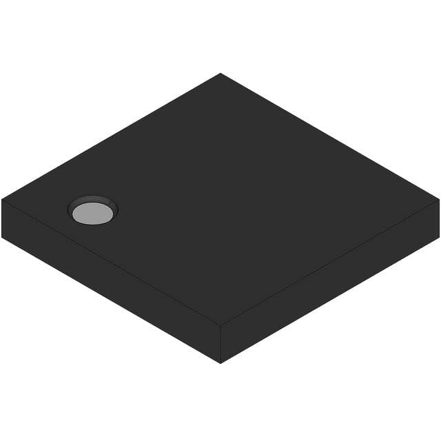
- Part No.:
- ISL24111IRTZ
- Manufacturer:
- Renesas
- Category:
- Power Management - Specialized
- Package:
- 24-WFQFN Exposed Pad
- Datasheet:
-
 ISL24111IRTZ.pdf
- Description:
- IC LOGIC LEVEL SHIFTER 24TQFN
- Quantity:
- Payment:

- Shipping:

Inventory:1,640
Please send an inquiry. Send us your inquiry, and we will respond immediately.
Product details
Overview
ISL24111IRTZ from Renesas Electronics is a 9-channel high-voltage TFT-LCD logic level shifter with gate shaping function, designed to convert TCON-generated low-voltage timing signals into ±54V/60V high-power outputs for Gate-In-Panel (GIP) driving. It delivers +460mA source / −730mA sink peak current per channel (OUT1–OUT7), supports 50ns propagation delay, and operates across −40°C to +85°C.
For engineers reviewing the ISL24111IRTZ datasheet, ISL24111IRTZ pinout, ISL24111IRTZ application, or ISL24111IRTZ equivalent, key selection considerations include its dual positive supply rails (VON1/VON2), channel-grouped rise/fall times (300ns/200ns for OUT1–OUT7; 520ns/350ns for OUT8–OUT9), gate shaping capability on OUT1–OUT6, and thermally enhanced 24-lead 4×4mm TQFN package.
Technical Context
The ISL24111IRTZ implements two independent high-voltage output groups: OUT1–OUT7 powered by VON1 (up to +60V) and VOFF (down to −54V); OUT8–OUT9 powered by VON2 (+60V) and same VOFF rail. Each group uses dedicated low-impedance output stages optimized for capacitive GIP loads up to 5000pF.
Gate shaping is enabled via FCLK input and applies only to OUT1–OUT6; OUT7–OUT9 operate in direct-input-tracking mode. The device requires separate logic-level enable control (EN) and does not integrate internal charge pumps or level-shifting reference generation - all high-voltage rails are externally supplied.
Key Specifications
| Parameter | Value and Actual Design Meaning |
|---|---|
| Channels | 9 independent high-voltage outputs, split as OUT1–OUT7 and OUT8–OUT9 with separate VON supplies |
| Output Voltage Range | −54V to +60V - supports full swing for amorphous silicon gate drivers in large-panel GIP architectures |
| Peak Output Current | +460mA / −730mA (OUT1–OUT7); enables fast charging/discharging of >5000pF panel gate lines |
| Propagation Delay | 50ns typical (low-to-high) - ensures tight timing alignment across multi-channel GIP timing sequences |
| Rise/Fall Time | 300ns/200ns (OUT1–OUT7); 520ns/350ns (OUT8–OUT9) - optimized for flicker reduction and EMI control per channel group |
| Operating Temperature | −40°C to +85°C ambient - qualified for industrial-grade TFT-LCD monitors and embedded display systems |
| Supply Current | 4.5mA quiescent - minimal overhead for system power budgeting in always-on display controllers |
Pinout & Package
ISL24111IRTZ is housed in a thermally enhanced 24-lead 4×4mm TQFN package with exposed thermal pad (RTZ suffix). Pin assignment follows Renesas standard layout for high-voltage level shifters with dual VON rails and shared VOFF.
| Pin/Terminal | Circuit Role | Design Meaning |
|---|---|---|
| VON1 | Positive supply for OUT1–OUT7 | Must be decoupled locally; sets upper voltage limit (+60V max) for first output group |
| VON2 | Positive supply for OUT8–OUT9 | Independent rail allows asymmetric drive strength or voltage tuning for edge gate lines |
| VOFF | Negative supply for all outputs | Common −54V rail; requires low-ESR capacitor and low-inductance return path |
| FCLK | Gate shaping clock input | Controls pulse-width modulation for OUT1–OUT6 to reduce panel power and flicker |
| EN | Global enable input (active-high) | Synchronizes all 9 channels; must meet tENH/tENL timing relative to input signals |
| IN1–IN9 | Logic-level input signals (1.8V/3.3V compatible) | Accept standard TCON timing waveforms; no internal level translation required |
| OUT1–OUT9 | High-voltage level-shifted outputs | OUT1–OUT6 support gate shaping; OUT7–OUT9 track inputs directly with fixed delay |
Key Features
| Feature | Design Value |
|---|---|
| Dual VON rail architecture | Enables independent optimization of drive strength and voltage margin for center vs. edge gate lines in large-format LCDs |
| Channel-grouped timing performance | 300ns/200ns (OUT1–OUT7) and 520ns/350ns (OUT8–OUT9) rise/fall ensure balanced settling across panel width |
| Gate shaping on OUT1–OUT6 | Reduces RMS current and panel power consumption by modulating output pulse width without compromising vertical resolution |
| High capacitive load drive | Rated for 5000pF loads - sufficient for 1080p+ GIP panels with long trace routing and multiple gate line segments |
| Thermally enhanced TQFN | 4×4mm footprint with exposed pad supports >1.5W continuous dissipation under typical GIP switching duty cycles |
Applications
| Large-Format TFT-LCD Monitor | TFT-LCD TV with Gate-On-Array (GOA) |
|---|---|
Use Scenario: Driving 23.8″–32″ IPS panels with integrated GOA circuitry requiring precise gate pulse timing and low flicker. IC Role / Device Role / Timing Role: High-voltage level shifter converting TCON LVDS timing signals into ±54V gate pulses for row-by-row pixel activation. Use Value: Dual VON rails allow fine-tuned drive strength on outer gate lines (OUT8–OUT9) to compensate for RC delay mismatch across wide panels. | Use Scenario: Replacing discrete MOSFET-based gate drivers in cost-sensitive 43″–55″ TV panels using Amorphous Silicon Gate (ASG) architecture. IC Role / Device Role / Timing Role: Integrated 9-channel level shifter eliminating external high-voltage transistors and associated gate resistors/layout area. Use Value: 50ns propagation delay and matched channel timing ensure sub-1μs inter-channel skew - critical for avoiding vertical banding artifacts. |
| Notebook Display with GIP | Industrial Tablet HMI Panel |
Use Scenario: Enabling slim bezel designs in 13.3″–15.6″ notebooks using Gate-In-Panel architecture with reduced gate driver IC count. IC Role / Device Role / Timing Role: Consolidating nine gate line drivers into single IC to minimize PCB layer count and EMI from parallel high-voltage traces. Use Value: Gate shaping on OUT1–OUT6 cuts panel dynamic power by ~12% during static image display, extending battery life. | Use Scenario: Operating in extended temperature environments (−40°C to +85°C) for medical or ruggedized tablet HMIs with sunlight-readable LCDs. IC Role / Device Role / Timing Role: Reliable high-voltage level shifting under thermal stress, maintaining <1% pulse width distortion across full temperature range. Use Value: Thermally enhanced TQFN package sustains 1.2W dissipation at +85°C ambient without derating - verified per Renesas thermal characterization report. |
Equivalent & Alternatives
The following parts are listed as comparable options for similar high-voltage TFT-LCD level shifting applications.
| Alternative Part | Technical Difference | Application Difference | Selection Advice |
|---|---|---|---|
| ISL24110IRTZ | 8-channel version; no VON2 rail; OUT8 shares VON1 with OUT1–OUT7 | Lacks independent edge-line drive tuning; unsuitable for asymmetric panel layouts requiring OUT8–OUT9 voltage differentiation | Select when panel gate count ≤8 and VON rail sharing is acceptable for cost reduction |
| BD8152FVM | 10-channel; integrates charge pump; max VOUT = ±45V; no gate shaping function | Lower voltage rating limits use in high-resolution panels requiring >±50V swing; lacks flicker-reduction capability | Prefer for compact designs where board space is constrained and gate shaping is not required |
Compared with ISL24111IRTZ, ISL24110IRTZ reduces channel count and eliminates VON2 flexibility but lowers BOM cost, while BD8152FVM trades gate shaping and higher voltage range for integrated charge pump convenience and smaller footprint - choice depends on panel voltage, flicker requirements, and layout constraints.
Availability
ISL24111IRTZ is available at Aetrix Electronics and suitable for TFT-LCD monitor design, Gate-On-Array (GOA) integration, and industrial HMI panel development requiring stable component supply and guaranteed long-term availability.
Supply support for ISL24111IRTZ includes scheduled delivery planning, volume procurement assistance, BOM continuity management, traceable sourcing, and lifecycle availability coordination for OEM customers, industrial embedded developers, connected-device designers, and electronics production programs.
Manufacturer
Renesas Electronics is a global semiconductor leader specializing in microcontrollers, analog, power, and mixed-signal solutions for automotive, industrial, and consumer applications.
The ISL24111IRTZ belongs to Renesas' display interface and timing IC portfolio, engineered specifically for high-reliability, high-voltage TFT-LCD gate driver consolidation in large-format and portable displays.
FAQ
What is the maximum capacitive load the ISL24111IRTZ can drive reliably?
The ISL24111IRTZ is rated to drive up to 5000pF per output channel under specified conditions. This capacity supports large-panel Gate-In-Panel configurations with long trace lengths and distributed gate capacitance. Performance validation includes rise/fall time and overshoot limits maintained at this load level across −40°C to +85°C, as confirmed in Renesas Application Note AN1723 for ISL24111IRTZ.
Does the ISL24111IRTZ require external charge pumps or level-shifting references?
No, the ISL24111IRTZ does not integrate charge pumps or internal references. All high-voltage rails - VON1, VON2, and VOFF - must be supplied externally. This architecture provides full design control over voltage margins and sequencing but requires careful layout of high-voltage decoupling and ground isolation. The ISL24111IRTZ datasheet specifies minimum capacitor values and placement guidelines for each rail.
Which output channels support gate shaping functionality on the ISL24111IRTZ?
Only OUT1 through OUT6 support gate shaping, controlled via the FCLK input signal. OUT7 tracks its input IN7 directly with fixed propagation delay, while OUT8 and OUT9 similarly follow IN8 and IN9 without shaping. This partitioning allows flicker reduction on primary gate lines while preserving timing fidelity on critical edge or reset lines - a key feature documented in the ISL24111IRTZ functional description section.
What is the thermal pad configuration for the ISL24111IRTZ TQFN package?
The ISL24111IRTZ uses a 24-lead 4×4mm TQFN package (RTZ suffix) with an exposed thermal pad on the bottom surface. Renesas recommends soldering this pad to a dedicated thermal copper plane on the PCB using a 3×3 array of thermal vias to internal ground or dedicated thermal layers. Thermal resistance θJA is 32°C/W under JEDEC JESD51-7 conditions, and the ISL24111IRTZ thermal design guide specifies minimum pad size and via count to maintain junction temperature below 125°C.
Can the ISL24111IRTZ operate with 1.8V logic-level inputs?
Yes, the ISL24111IRTZ accepts 1.8V CMOS-compatible logic inputs on IN1–IN9. Input thresholds are defined as VIL ≤ 0.65V and VIH ≥ 1.15V at VDD = 3.3V, ensuring robust operation with both 1.8V and 3.3V TCON outputs. The ISL24111IRTZ datasheet confirms noise margin and timing parameters remain valid across this input voltage range, with no level-shifting circuitry required upstream of the ISL24111IRTZ.
ISL24111IRTZ Specifications
- Product attributes
- Attribute value
- Manufacturer:
- Renesas
- Series:
- -
- Package/Case:
- 24-WFQFN Exposed Pad
- Packaging:
- Tube
- Product Status:
- Obsolete
- Applications:
- TFT-LCD Monitors
- Current - Supply:
- 4.5mA
- Voltage - Supply:
- 60V
- Operating Temperature:
- -40°C ~ 85°C
- Grade:
- -
- Qualification:
- -
- Mounting Type:
- Surface Mount
- Supplier Device Package:
- 24-TQFN (4x4)
ISL24111IRTZ FAQ
1.How can I place an order for ISL24111IRTZ through Aetrix?
Please submit a Request for Quotation (RFQ) for ISL24111IRTZ on Aetrix. Our sales agent will provide a competitive quotation and guide you through the order confirmation once you accept the terms.
2.Are the price and stock information for ISL24111IRTZ reliable?
The price and inventory of ISL24111IRTZ are updated periodically and may fluctuate due to market conditions. Stock and pricing data are typically refreshed every 24 hours. Quotation validity for ISL24111IRTZ is usually 5 days.
3.What payment methods are accepted for ISL24111IRTZ?
We accept Wire Transfer, PayPal, Credit Card, Western Union, MoneyGram, and Escrow for ISL24111IRTZ transactions.
Note: Certain payment methods may incur a processing fee.
4.How is shipping managed for ISL24111IRTZ?
ISL24111IRTZ orders can be shipped via leading logistics carriers, including DHL, UPS, FedEx, TNT, or Registered Mail.
Once your ISL24111IRTZ order is processed, you will receive an email with the shipment details and tracking number.
Note: Tracking information may take up to 24 hours to appear. Express delivery typically takes 3–5 business days.
5.How can I obtain technical support or documentation for ISL24111IRTZ?
For technical support, including ISL24111IRTZ datasheets, pinout diagrams, or application guidance, please contact our engineering support team. They can provide detailed documentation and assistance for your ISL24111IRTZ requirements.
6.How does Aetrix verify that ISL24111IRTZ is sourced from the original manufacturer or authorized distributors?
All ISL24111IRTZ products on Aetrix are procured from qualified distributors and authorized channels. Our dedicated quality assurance team conducts strict verification, including traceability checks and, if necessary, third-party testing. This ensures that ISL24111IRTZ meets industry standards.
7.What is the process for return or replacement of ISL24111IRTZ?
All ISL24111IRTZ units undergo pre-shipment inspection (PSI). If there is an issue with ISL24111IRTZ, returns or replacements are accepted under the following conditions:
1.Quantity discrepancies, incorrect items, or visible external defects (such as breakage or corrosion), acknowledged by Aetrix.
2.The issue is reported within 90 days of delivery.
3.The ISL24111IRTZ part is unused and in its original packaging.
Return procedure for ISL24111IRTZ:
1.Submit a request within 90 days.
2.Obtain a Return Material Authorization (RMA) from Aetrix.
ISL24111IRTZ Tags

-
TPS2511DGNR
Texas Instruments

-
UTC2000/MG
Microchip Technology

-
TUSB320HAIRWBR
Texas Instruments

-
TPS61252DSGR
Texas Instruments

-
PI5USB30216CXUAEX
Diodes Incorporated

-
SN6501DBVR
Texas Instruments

-
CYPD3177-24LQXQT
Infineon Technologies
-
SN6501QDBVRQ1
Texas Instruments

-
STUSB1600AQTR
STMicroelectronics

-
SN6505BDBVR
Texas Instruments
-
SN6501DBVT
Texas Instruments

-
TPS65150PWPR
Texas Instruments
Tech Hub

TTL and CMOS logic families differ in thresholds, loading, output drive, power and timing. This engineering guide compares 74HC and 74HCT, calculates noise margins and checks 3.3 V/5 V compatibility.

A practical engineering guide to 3.3V and 5V logic compatibility, input thresholds, resistor dividers, translator ICs, MOSFET level shifting, I2C pull-ups, timing limits and power-sequencing risks.

The 74HC595 uses push-pull logic outputs, while the TPIC6B595 uses 50 V open-drain DMOS sinks for higher-power loads. This guide compares timing, current limits, 3.3 V interfacing, load wiring, thermal…

The 74HC595 converts serial data into eight stable parallel outputs. This guide covers pin functions, shift and storage timing, OE and MR behavior, drive-current limits, cascading, voltage compatibilit…

A technical comparison of level-sensitive latches and edge-triggered flip-flops, covering timing windows, setup and hold limits, master–slave operation, time borrowing, race-through, HDL inference and…

A D latch stores one bit while Enable controls when data can pass. This reference covers gate-level operation, truth tables, transparency, setup and hold timing, LE versus OE, common ICs and practical …

An SR latch stores one bit through cross-coupled feedback. This engineering reference covers NOR and NAND implementations, truth tables, forbidden-state recovery, gated operation, switch debouncing, fa…

Latch circuits retain one bit through feedback. This technical reference covers SR and D latches, truth tables, transparency, timing limits, latch-versus-flip-flop behavior, applications and common log…

An engineering guide to LED driver operation, constant-current and constant-voltage outputs, linear and switching topologies, dimming, IC selection, calculations, replacement compatibility, and fault c…

Operational amplifier guide covering op amp basics, feedback, ideal vs real op amps, common configurations, buffer circuits, offset, bias current, gain-bandwidth, slew rate, rail-to-rail limits and sel…


