Send an Inquiry

To receive a quote for your project, please fill in the following information, and we’ll get back to you promptly.

Name*
Company*
Email Address*
Phone/WhatsApp
Part Number*
Quantity*
Message
Submit Inventory List

Please fill in the following information, and we’ll get back to you promptly.

Name*
Company*
Email Address*
Phone/WhatsApp
Upload My List
Message

Semtech Corporation JANS1N6102AUS

Part No.:
JANS1N6102AUS
Manufacturer:
Semtech Corporation
Category:
TVS Diodes
Package:
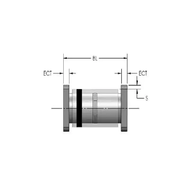
SQ-MELF
Datasheet:
AetrixJANS1N6102AUS.pdf
Description:
TVS BI 5V2 500W HR SM
Quantity:
Payment:
Payment
Shipping:
Shipping

Inventory:3,868

Please send an inquiry. Send us your inquiry, and we will respond immediately.

Part Number
Quantity*
Price
Name*
Company
Email*
Comments

Product details

Overview

JANS1N6102AUS from Semtech is a transient diverting suppressor (TDS) designed for high-energy EOS protection of 22V-rated power or I/O lines, featuring ±30kV IEC 61000-4-2 ESD immunity, 40A peak pulse current (8/20μs), 27.5–28V clamping voltage at 40A, and 20mΩ dynamic resistance. It protects USB Type-C power delivery buses, load switch inputs, and industrial interfaces where stable clamping under temperature and current stress is critical.

For engineers reviewing the JANS1N6102AUS datasheet, pinout, applications, or equivalent options, key selection criteria include its constant-clamp FET-based architecture, DFN 1.6×1.6mm 6-lead package with triple parallel input/ground terminals, 175pF junction capacitance at 22V, and compliance with IEC 61000-4-4 (±4kV EFT) and IEC 61000-4-5 (±1kV surge).

Technical Context

The JANS1N6102AUS implements a precision-triggered shunt FET architecture-unlike conventional TVS diodes-where a dedicated trigger circuit activates a low-RDS(on) FET during overvoltage events. This yields near-constant clamping voltage across 24–40A peak pulse current and −40°C to +125°C operating temperature.

It operates as a bidirectional, single-line protector with 22V reverse stand-off voltage (VRWM) and 25–27.9V breakdown (VBR at 1mA), delivering 1120W peak pulse power (8/20μs) while maintaining <600nA leakage at VRWM. Its functional diagram confirms three parallel IN pins (4–6) and three parallel GND pins (1–3) for minimized inductance and maximized surge current sharing.

Key Specifications

ParameterValue and Actual Design Meaning
Working Voltage22V reverse stand-off (VRWM): defines maximum continuous bus voltage before activation
Clamping Voltage27.5–28V at 40A (8/20μs): ensures protected ICs (e.g., USB PD controllers) remain below damage thresholds
Peak Pulse Current40A (8/20μs): meets IEC 61000-4-5 Level 4 industrial surge immunity requirements
ESD Withstand±30kV contact & air (IEC 61000-4-2): exceeds automotive and industrial ESD robustness standards
Dynamic Resistance20mΩ (8/20μs): enables flat clamping curve by minimizing ΔV = I × RDYN rise
Junction Capacitance175pF at 22V, 1MHz: low enough for 20V power rail protection without signal integrity impact
EFT Immunity±4kV (5/50ns, 100kHz/5kHz, IEC 61000-4-4): sustains operation during repetitive fast transients

Pinout & Package

Package: DFN 1.6 mm × 1.6 mm × 0.55 mm, 6-lead, Pb-free, RoHS/WEEE compliant, UL 94V-0 molding compound.

Pin/TerminalCircuit RoleDesign Meaning
1, 2, 3GNDParallel ground terminals-must all be connected to minimize inductance and maximize surge current handling
4, 5, 6INParallel input terminals-connect directly to protected line (e.g., VBus); shared path reduces impedance and thermal stress

Key Features

FeatureDesign Value
FET-based clampingReplaces PN-junction TVS with active shunt FET, enabling <0.1Ω effective RDS(on) and flat clamping vs. current/temperature
Triple-terminal input & groundThree parallel IN (pins 4–6) and GND (pins 1–3) paths reduce trace inductance and distribute surge current evenly
Stable clamping over temperatureClamping voltage remains 27.5–28V from −40°C to +125°C-critical for industrial and automotive ambient conditions
Low dynamic resistance20mΩ measured between 1A–40A (8/20μs) ensures minimal voltage overshoot during fast-rising surges
High-energy surge rating1120W peak pulse power (8/20μs) supports repeated lightning-induced transients in remote metering and robotics

Applications

USB Type-C Power Delivery ProtectionIndustrial Load Switch Input Protection

Use Scenario: Protecting 20V–22V VBus lines in USB-C connectors supporting Power Delivery up to 100W.

IC Role / Device Role / Timing Role: Primary EOS shunt protector placed at connector entry point, clamping transients before they reach PD controller or load switch.

Use Value: Maintains 27.5–28V clamping across full 40A surge and −40°C to +125°C-prevents false triggering or latch-up seen with conventional TVS diodes.

Use Scenario: Safeguarding input terminals of industrial-grade load switches (e.g., HS2950P) exposed to lightning-induced surges in remote meters or factory automation.

IC Role / Device Role / Timing Role: Front-end transient diverter that limits voltage across the load switch's internal FET drain-source, preventing gate oxide rupture or avalanche failure.

Use Value: Enables use of cost-optimized load switches without requiring oversized internal protection-reduces BOM count and PCB area.

IoT Edge Node Power Rail ProtectionStorage Device DC Power Input Protection

Use Scenario: Securing 12–24V DC input rails in battery-powered IoT gateways deployed outdoors or in electrically noisy environments.

IC Role / Device Role / Timing Role: Single-device solution for combined ESD, EFT, and surge immunity on main power input, eliminating need for multi-stage protection.

Use Value: 175pF capacitance avoids power rail instability; ±4kV EFT rating ensures reliable operation during motor switching noise in smart building systems.

Use Scenario: Protecting SATA or NVMe SSD power inputs (3.3V/5V/12V rails) against hot-plug transients and backplane coupling in enterprise storage enclosures.

IC Role / Device Role / Timing Role: High-current transient suppressor placed at board edge, routing surge energy directly to chassis ground via low-inductance layout.

Use Value: 40A peak pulse capability handles worst-case hot-swap events; triple-GND pins support low-impedance grounding required for high-speed storage reliability.

Equivalent & Alternatives

The following parts are listed as comparable options for similar transient suppression applications.

Alternative PartTechnical DifferenceApplication DifferenceSelection Advice
TDS2211P.CSame silicon die, identical electrical specs, identical DFN 1.6×1.6mm package; differs only in tape-and-reel packaging (3,000 pcs/reel vs. JANS1N6102AUS military-grade marking and screening)Commercial-grade variant; not qualified to MIL-PRF-19500/560 or JAN specificationsSelect JANS1N6102AUS for aerospace, defense, or high-reliability industrial programs requiring radiation-hardened or extended-temperature screening.
uClamp2411ZA24V working voltage, lower 20A IPP rating, higher 30V clamping at 20A, 0.25pF capacitance optimized for CC/SBU lines-not rated for 40A or power rail dutyDesigned for low-capacitance data-line protection (CC/SBU), not power rail or high-current surge diversionUse uClamp2411ZA only for auxiliary signal lines; JANS1N6102AUS is required for primary VBus or load-switch input protection.

Compared with TDS2211P.C and uClamp2411ZA, JANS1N6102AUS delivers military-grade reliability, full 40A surge handling, and constant 27.5–28V clamping-making it the sole option for mission-critical 22V power rail protection where thermal stability and surge margin are non-negotiable.

Availability

JANS1N6102AUS is available at Aetrix Electronics and suitable for USB Type-C power delivery systems, industrial load switch inputs, and ruggedized IoT edge node designs requiring stable component supply across extended temperature and surge stress conditions.

Supply support for JANS1N6102AUS includes scheduled delivery planning, volume procurement assistance, BOM continuity management, traceable sourcing, and lifecycle availability coordination for OEM customers, industrial embedded developers, connected-device designers, and electronics production programs.

Manufacturer

Semtech Corporation is a U.S.-based fabless semiconductor company specializing in high-performance analog and mixed-signal ICs for precision sensing, protection, and signal integrity.

JANS1N6102AUS belongs to Semtech's Transient Diverting Suppressor (TDS) product line-engineered specifically to replace conventional TVS diodes in high-reliability power rail protection with superior clamping stability, temperature resilience, and surge endurance.

FAQ

What is the primary protection function of JANS1N6102AUS?

JANS1N6102AUS functions as a transient diverting suppressor that actively shunts high-energy EOS events-including ESD, EFT, and lightning-induced surges-to ground using a precision-triggered FET. Unlike passive TVS diodes, it maintains a stable 27.5–28V clamping voltage across its full 40A peak pulse current range and −40°C to +125°C operating temperature, making JANS1N6102AUS ideal for protecting sensitive 22V power rails in demanding environments.

How does JANS1N6102AUS differ from standard TVS diodes in clamping behavior?

JANS1N6102AUS uses a surge-rated FET and dedicated trigger circuit instead of a PN junction, resulting in near-constant clamping voltage (27.5–28V) regardless of peak pulse current (24–40A) or temperature (−40°C to +125°C). Standard TVS diodes exhibit linear clamping rise (VC = VBR + IPP × RDYN) and degrade with temperature-whereas JANS1N6102AUS clamping remains flat, ensuring predictable protection margins in JANS1N6102AUS deployments.

What is the correct PCB layout practice for JANS1N6102AUS to achieve rated 40A performance?

To achieve full 40A surge rating, all three IN pins (4–6) must be connected via a single low-inductance trace to the protected line, and all three GND pins (1–3) must connect directly to a solid ground plane using multiple vias. JANS1N6102AUS must be placed adjacent to the connector-minimizing trace length-to prevent coupling into adjacent nets. Layout deviations reduce effective surge current handling and compromise JANS1N6102AUS's constant-clamp advantage.

Is JANS1N6102AUS compatible with automated SMT assembly processes?

Yes, JANS1N6102AUS uses a standard DFN 1.6 mm × 1.6 mm × 0.55 mm package with exposed pad-less construction and lead-free terminations, fully compatible with reflow soldering per IPC/JEDEC J-STD-020. Its marking code "T22" and pin-1 dot enable optical recognition. JANS1N6102AUS has been validated for high-yield placement and solder joint integrity in volume manufacturing-no special stencil or profile adjustments are needed beyond standard DFN guidelines.

Does JANS1N6102AUS require external biasing or control signals to operate?

No, JANS1N6102AUS is a fully autonomous, two-terminal device requiring no external power, bias, or control signals. Its internal trigger circuit self-activates when transient voltage exceeds the breakdown threshold (~25–27.9V), turning on the shunt FET within nanoseconds. This passive operation makes JANS1N6102AUS drop-in compatible with existing TVS footprints and eliminates design overhead-JANS1N6102AUS functions immediately upon installation.

JANS1N6102AUS Specifications

Product attributes
Attribute value
Manufacturer:
Semtech Corporation
Package/Case:
SQ-MELF
Series:
-
Packaging:
Bulk
Product Status:
Discontinued at Digi-Key
Type:
Zener
Unidirectional Channels:
-
Bidirectional Channels:
1
Voltage - Reverse Standoff (Typ):
5.2V
Voltage - Breakdown (Min):
6.46V
Voltage - Clamping (Max) @ Ipp:
10.5V
Current - Peak Pulse (10/1000µs):
47.6A
Power - Peak Pulse:
500W
Power Line Protection:
No
Applications:
General Purpose
Capacitance @ Frequency:
-
Operating Temperature:
-
Grade:
-
Qualification:
-
Mounting Type:
Surface Mount
Supplier Device Package:
-

JANS1N6102AUS FAQ

1.How can I place an order for JANS1N6102AUS through Aetrix?

Please submit a Request for Quotation (RFQ) for JANS1N6102AUS on Aetrix. Our sales agent will provide a competitive quotation and guide you through the order confirmation once you accept the terms.

2.Are the price and stock information for JANS1N6102AUS reliable?

The price and inventory of JANS1N6102AUS are updated periodically and may fluctuate due to market conditions. Stock and pricing data are typically refreshed every 24 hours. Quotation validity for JANS1N6102AUS is usually 5 days.

3.What payment methods are accepted for JANS1N6102AUS?

We accept Wire Transfer, PayPal, Credit Card, Western Union, MoneyGram, and Escrow for JANS1N6102AUS transactions.

Note: Certain payment methods may incur a processing fee.

4.How is shipping managed for JANS1N6102AUS?

JANS1N6102AUS orders can be shipped via leading logistics carriers, including DHL, UPS, FedEx, TNT, or Registered Mail.

Once your JANS1N6102AUS order is processed, you will receive an email with the shipment details and tracking number.

Note: Tracking information may take up to 24 hours to appear. Express delivery typically takes 3–5 business days.

5.How can I obtain technical support or documentation for JANS1N6102AUS?

For technical support, including JANS1N6102AUS datasheets, pinout diagrams, or application guidance, please contact our engineering support team. They can provide detailed documentation and assistance for your JANS1N6102AUS requirements.

6.How does Aetrix verify that JANS1N6102AUS is sourced from the original manufacturer or authorized distributors?

All JANS1N6102AUS products on Aetrix are procured from qualified distributors and authorized channels. Our dedicated quality assurance team conducts strict verification, including traceability checks and, if necessary, third-party testing. This ensures that JANS1N6102AUS meets industry standards.

7.What is the process for return or replacement of JANS1N6102AUS?

All JANS1N6102AUS units undergo pre-shipment inspection (PSI). If there is an issue with JANS1N6102AUS, returns or replacements are accepted under the following conditions:

1.Quantity discrepancies, incorrect items, or visible external defects (such as breakage or corrosion), acknowledged by Aetrix.

2.The issue is reported within 90 days of delivery.

3.The JANS1N6102AUS part is unused and in its original packaging.

Return procedure for JANS1N6102AUS:

1.Submit a request within 90 days.

2.Obtain a Return Material Authorization (RMA) from Aetrix.

JANS1N6102AUS Tags

  • JANS1N6102AUS
  • JANS1N6102AUS PDF
  • JANS1N6102AUS Datasheet
  • JANS1N6102AUS Specifications
  • JANS1N6102AUS Images
  • Semtech Corporation
  • Semtech Corporation JANS1N6102AUS
  • Buy JANS1N6102AUS
  • JANS1N6102AUS Price
  • JANS1N6102AUS Distributor
  • JANS1N6102AUS Supplier
  • JANS1N6102AUS Wholesale
Related Products
ESD9B5.0ST5G
ESD9B5.0ST5G

onsemi

DESD3V3E1BL-7B
DESD3V3E1BL-7B

Diodes Incorporated

ESD5Z3.3T1G
ESD5Z3.3T1G

onsemi

D5V0H1B2LP-7B
D5V0H1B2LP-7B

Diodes Incorporated

D5V0P1B2LP-7B
D5V0P1B2LP-7B

Diodes Incorporated

DESD5V0U1BA-7
DESD5V0U1BA-7

Diodes Incorporated

ESD5Z5.0T1G
ESD5Z5.0T1G

onsemi

DESD5V0U1BB-7
DESD5V0U1BB-7

Diodes Incorporated

D12V0L1B2LP-7B
D12V0L1B2LP-7B

Diodes Incorporated

PESD2V0Y1BSFYL
PESD2V0Y1BSFYL

Nexperia USA Inc.

DF2S5M4CT,L3F
DF2S5M4CT,L3F

Toshiba Semiconductor and Storage

D5V0L1B2WS-7
D5V0L1B2WS-7

Diodes Incorporated

Tech Hub

Search

Search

PRODUCT

PRODUCT

PHONE

PHONE

USER

USER