
 My Inquiry
 My Account


STMicroelectronics L9779WD-SPI-TR
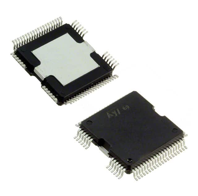
- Part No.:
- L9779WD-SPI-TR
- Manufacturer:
- STMicroelectronics
- Category:
- Power Management - Specialized
- Package:
- 64-BQFP Exposed Pad
- Datasheet:
-
 L9779WD-SPI-TR.pdf
- Description:
- MULTIFUNCTION IC FOR ENGINE MANA
- Quantity:
- Payment:

- Shipping:

Inventory:532
Please send an inquiry. Send us your inquiry, and we will respond immediately.
Product details
Overview
L9779WD-SPI-TR from STMicroelectronics is a multifunction automotive IC for engine management systems, integrating 5 V and 3.3 V logic regulators, 5 V tracking sensor supply, high-speed CAN transceiver, ISO9141 K-Line interface, and 20 protected low-side outputs (including injector, relay, and O₂ heater drivers). It implements Secure Engine Off (SEO), adaptive flying wheel (VRS) sensing, and VDA 2.0–compliant 3-level watchdog in BCD6S technology.
For engineers reviewing the L9779WD-SPI-TR datasheet, L9779WD-SPI-TR pinout, L9779WD-SPI-TR application, or L9779WD-SPI-TR equivalent, this device serves as a system power and signal management hub in ECU designs-requiring precise reset sequencing, thermal shutdown response, SPI-configurable power stage modes, and fault-diagnosable driver outputs under automotive voltage transients (load dump, cold crank).
Technical Context
The L9779WD-SPI-TR integrates six functional domains: dual linear regulators (5 V/300 mA, 3.3 V/200 mA), a 5 V tracking sensor supply with ±1% accuracy, four IGBT pre-drivers (IGN1–IGN4) with parallel input support, configurable power stages (CPS) supporting stepper motor or H-bridge operation, and dual serial interfaces (SPI + ISO9141/K-Line) with independent register maps.
Its power management core includes Smart Reset with programmable delay, Power Latch with SEO logic to enforce safe ignition-off sequence, and thermal warning/shutdown at 150 °C with hysteresis. The flying wheel interface features auto-adaptive amplitude/time filtering for variable-reluctance sensors across RPM ranges from idle to 15,000 rpm.
Key Specifications
| Parameter | Value and Actual Design Meaning |
|---|---|
| Logic Regulators | 5 V / 300 mA and 3.3 V / 200 mA linear regulators-supply MCU, sensors, and logic without external LDOs. |
| Sensor Supply | 5 V tracking supply (±1% accuracy, 100 mA)-powers crank/cam position sensors with stable bias under battery variation. |
| CAN Transceiver | High-speed CAN compliant with ISO 11898-2-enables real-time diagnostics and ECU-to-ECU communication at up to 1 Mbps. |
| Low-Side Outputs | 20 protected channels: OUT1–4 (injectors, 1.5 A peak), OUT5–7 (O₂ heaters, 3 A), OUT13–18 (relays, 2.5 A), OUT20 (low-current, 100 mA). |
| VRS Interface | Flying wheel input with adaptive time/amplitude control-detects missing teeth, supports 0.2–15 kHz input without external conditioning. |
| Watchdog | VDA 2.0–compliant 3-level watchdog (WDA) with independent timeout, error counter, and diagnostic response registers. |
| SPI Interface | 16-bit frame, 4-MHz max clock-configures all power stages, diagnostics, and safety registers with CRC-protected command protocol. |
Pinout & Package
Package: HiQUAD-64 - thermally enhanced power package with exposed die pad, designed for high-power dissipation in under-hood automotive environments (RthJA = 25 °C/W, RthJC = 2.5 °C/W).
| Pin/Terminal | Circuit Role | Design Meaning |
|---|---|---|
| VDD5 | 5 V regulator output | Primary logic supply rail; powers internal digital blocks and external MCU core logic. |
| VDD33 | 3.3 V regulator output | Secondary logic rail for peripherals, ADC references, and CAN transceiver I/O. |
| VSUP | Main battery input (VBATT) | Input for all regulators and power stages; withstands load dump up to 40 V (ISO 7637-2 Pulse 5a). |
| KEY_ON | Ignition switch sense | Detects ignition state transitions; triggers power-up/down sequences and SEO latch activation. |
| RST | Reset output | Open-drain reset signal with programmable delay; asserts during brown-out, thermal shutdown, or watchdog timeout. |
| SPI_MOSI/SPI_MISO/SPI_SCK/SPI_CS | SPI interface signals | Full-duplex 16-bit command/data path for configuration, status readback, and fault logging. |
| CAN_H/CAN_L | CAN bus differential pair | Direct connection to vehicle CAN network; integrated common-mode choke and dominant timeout protection. |
| K_LINE | ISO9141 single-wire interface | Legacy diagnostics port compatible with OBD-II tools; supports 10.4 kbps asynchronous communication. |
| VRS_IN | Flying wheel sensor input | AC-coupled, adaptive threshold comparator for variable-reluctance crankshaft/camshaft sensors. |
| OUT1–OUT20 | Protected low-side driver outputs | Individually diagnosable channels with overcurrent, open-load, and short-to-battery detection. |
| IGN1–IGN4 | IGBT pre-driver outputs | High-current gate drivers (±1.5 A peak) with shoot-through prevention and Miller clamp. |
| OUTA–OUTD | Configurable power stage terminals | Support H-bridge, half-bridge, or parallel low-side modes via CONFIG_REG10; each rated 3 A continuous. |
Key Features
| Feature | Design Value |
|---|---|
| Secure Engine Off (SEO) | Hardware-enforced power-down sequence ensuring controlled shutdown of injectors, ignition, and CAN before main relay deactivation. |
| Adaptive VRS Interface | Self-tuning amplitude and timing thresholds eliminate manual calibration; maintains signal integrity across temperature and air-gap variations. |
| Diagnosable Power Stages | All 20 low-side outputs and 4 pre-drivers report open-load, short-to-VB, short-to-GND, and overtemperature faults via dedicated SPI diagnosis registers. |
| VDA 2.0 Watchdog | Three independent watchdog timers (WDA) with configurable timeouts, error counters, and non-maskable reset assertion on failure. |
| Thermal Protection | Two-stage thermal response: warning interrupt at 135 °C, hard shutdown at 150 °C with 15 °C hysteresis and automatic recovery. |
Applications
| Gasoline Engine Control Unit (ECU) | Diesel Common Rail ECU |
|---|---|
|
Use Scenario: Real-time management of fuel injection timing, ignition spark control, and exhaust gas recirculation in inline-4 gasoline engines. IC Role / Device Role / Timing Role: Central power and signal manager-regulates logic supplies, drives 4 injectors (OUT1–4), 4 ignition pre-drivers (IGN1–IGN4), and monitors crank/cam position via VRS_IN. Use Value: Enables deterministic startup/shutdown sequencing (SEO), reduces external component count by integrating 5 V/3.3 V regulators and CAN transceiver, and supports OBD-II diagnostics via K-Line. |
Use Scenario: High-precision control of common rail pressure, pilot/main/post injections, and glow plug sequencing in turbocharged diesel ECUs. IC Role / Device Role / Timing Role: System supervisor-supplies 3.3 V to pressure sensor ADC, drives O₂ heater (OUT6/7), manages main relay (MRD), and logs faults via SPI for flash reprogramming. Use Value: Delivers ±1% sensor supply accuracy for rail pressure feedback, supports fast transient response during cold cranking (down to 3.5 V), and provides per-channel diagnosis for compliance with ISO 26262 ASIL-B. |
| Start-Stop System ECU | Motorcycle ECU |
|
Use Scenario: Managing battery regeneration, starter motor engagement, and seamless engine restart during vehicle stop phases. IC Role / Device Role / Timing Role: Power sequencer and safety monitor-uses KEY_ON sensing and Smart Reset to coordinate microcontroller wake-up, controls starter relay (OUT13–18), and enforces SEO during stop events. Use Value: Guarantees <50 ms restart latency via hardware-latched power states, prevents unintended restarts using VDA 2.0 watchdog, and survives repeated load dump pulses in 12 V start-stop architectures. |
Use Scenario: Compact engine management for 2-cylinder motorcycle platforms with space-constrained packaging and aggressive thermal cycling. IC Role / Device Role / Timing Role: Integrated driver hub-drives twin injectors (OUT1/2), twin ignition coils (IGN1/2), fan relay (OUT15), and communicates via CAN to dashboard cluster. Use Value: Eliminates need for discrete high-side drivers and external CAN controller; HiQUAD-64 package enables direct PCB heatsinking in sealed enclosures without forced airflow. |
Equivalent & Alternatives
The following parts are listed as comparable options for similar multifunction automotive power management applications.
| Alternative Part | Technical Difference | Application Difference | Selection Advice |
|---|---|---|---|
| NXP MC33816 | Single 5 V regulator (no 3.3 V output); no integrated CAN transceiver; uses SPI+SCI dual interface. | Lacks native K-Line support and VDA 2.0 watchdog; requires external CAN PHY and level-shifting for 3.3 V peripherals. | Select when CAN is handled externally and 3.3 V rail is generated locally; better suited for legacy SCI-based toolchains. |
| Renesas RH850/P1M | MCU with integrated power management IP (not standalone PMIC); no VRS interface or SEO logic. | Requires external VRS conditioner and relay drivers; lacks hardware-enforced SEO sequence and multi-rail regulation. | Select only for highly integrated SoC-based designs where firmware handles power sequencing and diagnostics. |
Compared with MC33816 and RH850/P1M, the L9779WD-SPI-TR delivers higher integration density (dual regulators + CAN + K-Line + VRS + SEO), reduces BOM count by ≥12 components, and provides hardware-verified ASIL-B–capable safety mechanisms without MCU dependency.
Availability
L9779WD-SPI-TR is available at Aetrix Electronics and suitable for gasoline/diesel engine control units, start-stop system ECUs, and motorcycle engine management requiring stable component supply across automotive production lifecycles (15+ years).
Supply support for L9779WD-SPI-TR includes scheduled delivery planning, volume procurement assistance, BOM continuity management, traceable sourcing, and lifecycle availability coordination for OEM customers, industrial embedded developers, connected-device designers, and electronics production programs.
Manufacturer
STMicroelectronics is a global semiconductor leader headquartered in Geneva, specializing in automotive-grade analog, power, and microcontroller solutions with ISO/TS 16949-certified manufacturing.
The L9779WD-SPI-TR belongs to ST's L97xx family of automotive power management ICs, designed specifically for engine control unit consolidation-replacing discrete regulators, drivers, and interface ICs with a single AEC-Q100 Grade 1 qualified device.
FAQ
What is the maximum allowable supply voltage for VSUP, and how does it handle load dump?
The VSUP pin supports absolute maximum voltage of 40 V per ISO 7637-2 Pulse 5a. Internal clamping circuitry limits energy dissipation during 40 V/400 ms load dump events, enabling direct connection to 12 V automotive battery without external TVS diodes. Thermal shutdown activates if junction temperature exceeds 150 °C during sustained overload.
How does the Smart Reset function differ from standard POR/BOR circuits?
Smart Reset combines power-on reset, brown-out detection, and software-controllable delay (via CONFIG_REG6) into one hardware block. Unlike basic POR, it holds RST active until VDD5 stabilizes *and* user-defined delay expires-ensuring MCU firmware initializes only after all internal regulators and clocks settle, preventing race conditions in safety-critical boot sequences.
Can the configurable power stages (OUTA–OUTD) be used simultaneously as both H-bridges and low-side switches?
No-OUTA–OUTD operate in mutually exclusive modes defined by CONFIG_REG10: either as four independent low-side switches, two H-bridges, or one 4-phase stepper driver. Mode selection is static per power cycle; dynamic reconfiguration requires full SPI register reload and reset assertion, making mixed-mode operation unsupported in runtime.
Is the K-Line (ISO9141) interface electrically compatible with standard OBD-II diagnostic tools?
Yes-the K_LINE pin meets ISO 9141-2 electrical specifications: 10.4 kbps nominal bit rate, 1.2–2.8 V logic levels, and integrated line termination. It supports standard diagnostic protocols (SAE J1850 VPW, ISO 14230 KWP2000) and interoperates with factory scan tools and aftermarket OBD-II adapters without level-shifting or external transceivers.
L9779WD-SPI-TR Specifications
- Product attributes
- Attribute value
- Manufacturer:
- STMicroelectronics
- Series:
- -
- Package/Case:
- 64-BQFP Exposed Pad
- Packaging:
- Tape & Reel (TR)
- Product Status:
- Active
- Applications:
- Engine Management
- Current - Supply:
- 550µA
- Voltage - Supply:
- 4.9V ~ 5.1V
- Operating Temperature:
- -40°C ~ 125°C
- Grade:
- -
- Qualification:
- -
- Mounting Type:
- Surface Mount
- Supplier Device Package:
- 64-HiQUAD
L9779WD-SPI-TR FAQ
1.How can I place an order for L9779WD-SPI-TR through Aetrix?
Please submit a Request for Quotation (RFQ) for L9779WD-SPI-TR on Aetrix. Our sales agent will provide a competitive quotation and guide you through the order confirmation once you accept the terms.
2.Are the price and stock information for L9779WD-SPI-TR reliable?
The price and inventory of L9779WD-SPI-TR are updated periodically and may fluctuate due to market conditions. Stock and pricing data are typically refreshed every 24 hours. Quotation validity for L9779WD-SPI-TR is usually 5 days.
3.What payment methods are accepted for L9779WD-SPI-TR?
We accept Wire Transfer, PayPal, Credit Card, Western Union, MoneyGram, and Escrow for L9779WD-SPI-TR transactions.
Note: Certain payment methods may incur a processing fee.
4.How is shipping managed for L9779WD-SPI-TR?
L9779WD-SPI-TR orders can be shipped via leading logistics carriers, including DHL, UPS, FedEx, TNT, or Registered Mail.
Once your L9779WD-SPI-TR order is processed, you will receive an email with the shipment details and tracking number.
Note: Tracking information may take up to 24 hours to appear. Express delivery typically takes 3–5 business days.
5.How can I obtain technical support or documentation for L9779WD-SPI-TR?
For technical support, including L9779WD-SPI-TR datasheets, pinout diagrams, or application guidance, please contact our engineering support team. They can provide detailed documentation and assistance for your L9779WD-SPI-TR requirements.
6.How does Aetrix verify that L9779WD-SPI-TR is sourced from the original manufacturer or authorized distributors?
All L9779WD-SPI-TR products on Aetrix are procured from qualified distributors and authorized channels. Our dedicated quality assurance team conducts strict verification, including traceability checks and, if necessary, third-party testing. This ensures that L9779WD-SPI-TR meets industry standards.
7.What is the process for return or replacement of L9779WD-SPI-TR?
All L9779WD-SPI-TR units undergo pre-shipment inspection (PSI). If there is an issue with L9779WD-SPI-TR, returns or replacements are accepted under the following conditions:
1.Quantity discrepancies, incorrect items, or visible external defects (such as breakage or corrosion), acknowledged by Aetrix.
2.The issue is reported within 90 days of delivery.
3.The L9779WD-SPI-TR part is unused and in its original packaging.
Return procedure for L9779WD-SPI-TR:
1.Submit a request within 90 days.
2.Obtain a Return Material Authorization (RMA) from Aetrix.
L9779WD-SPI-TR Tags

-
TPS2511DGNR
Texas Instruments

-
UTC2000/MG
Microchip Technology

-
TUSB320HAIRWBR
Texas Instruments

-
TPS61252DSGR
Texas Instruments

-
PI5USB30216CXUAEX
Diodes Incorporated

-
SN6501DBVR
Texas Instruments

-
CYPD3177-24LQXQT
Infineon Technologies
-
SN6501QDBVRQ1
Texas Instruments

-
STUSB1600AQTR
STMicroelectronics

-
SN6505BDBVR
Texas Instruments
-
SN6501DBVT
Texas Instruments

-
TPS65150PWPR
Texas Instruments
Tech Hub

A practical engineering and sourcing framework covering lifecycle verification, lifetime-buy calculations, replacement qualification, supplier checks and counterfeit-risk controls.

TTL and CMOS logic families differ in thresholds, loading, output drive, power and timing. This engineering guide compares 74HC and 74HCT, calculates noise margins and checks 3.3 V/5 V compatibility.

A practical engineering guide to 3.3V and 5V logic compatibility, input thresholds, resistor dividers, translator ICs, MOSFET level shifting, I2C pull-ups, timing limits and power-sequencing risks.

The 74HC595 uses push-pull logic outputs, while the TPIC6B595 uses 50 V open-drain DMOS sinks for higher-power loads. This guide compares timing, current limits, 3.3 V interfacing, load wiring, thermal…

The 74HC595 converts serial data into eight stable parallel outputs. This guide covers pin functions, shift and storage timing, OE and MR behavior, drive-current limits, cascading, voltage compatibilit…

A technical comparison of level-sensitive latches and edge-triggered flip-flops, covering timing windows, setup and hold limits, master–slave operation, time borrowing, race-through, HDL inference and…

A D latch stores one bit while Enable controls when data can pass. This reference covers gate-level operation, truth tables, transparency, setup and hold timing, LE versus OE, common ICs and practical …

An SR latch stores one bit through cross-coupled feedback. This engineering reference covers NOR and NAND implementations, truth tables, forbidden-state recovery, gated operation, switch debouncing, fa…

Latch circuits retain one bit through feedback. This technical reference covers SR and D latches, truth tables, transparency, timing limits, latch-versus-flip-flop behavior, applications and common log…

An engineering guide to LED driver operation, constant-current and constant-voltage outputs, linear and switching topologies, dimming, IC selection, calculations, replacement compatibility, and fault c…


