
 My Inquiry
 My Account


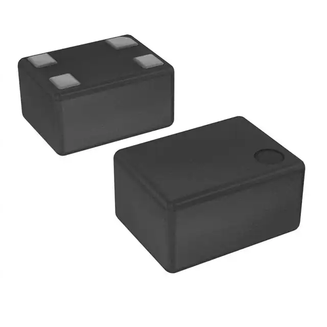
Texas Instruments LMK61E2-I4SIAR

- Part No.:
- LMK61E2-I4SIAR
- Manufacturer:
- Texas Instruments
- Category:
- Programmable Oscillators
- Package:
- 8-SMD Module
- Datasheet:
-
 LMK61E2-I4SIAR.pdf
- Description:
- PROTOTYPE
- Quantity:
- Payment:

- Shipping:

Inventory:3,856
Please send an inquiry. Send us your inquiry, and we will respond immediately.
Product details
Overview
LMK61E2-I4SIAR from Texas Instruments is an ultra-low jitter (90 fs RMS typical @ >100 MHz), programmable oscillator with integrated fractional-N PLL, 4.6–5.6 GHz VCO, and user-selectable LVPECL/LVDS/HCSL outputs in a 7 mm × 5 mm QFM-8 package. It features internal EEPROM for factory- or field-programmable default settings (e.g., 156.25 MHz LVPECL), I²C interface, ±50 ppm total frequency tolerance, and operates from a single 3.3 V supply across –40°C to +85°C. Used as a high-stability clock source for FPGA/processor reference, network line cards, and test equipment.
For engineers reviewing the LMK61E2-I4SIAR datasheet, LMK61E2-I4SIAR pinout, LMK61E2-I4SIAR application, or LMK61E2-I4SIAR equivalent, key selection criteria include RMS jitter performance at target output frequency, output format compatibility (LVPECL up to 1 GHz / LVDS up to 900 MHz / HCSL up to 400 MHz), PSRR (–70 dBc), frequency margining capability, and EEPROM-based self-start behavior without external configuration.
Technical Context
The LMK61E2-I4SIAR implements a fractional-N PLL architecture with a 4.6–5.6 GHz integrated VCO, 50 MHz crystal reference, and configurable integer/fractional feedback dividers. Its output stage supports three differential formats via register-controlled buffer selection, each with defined voltage swing, common-mode level, and rise/fall time specifications.
Power conditioning includes on-chip LDOs isolating analog PLL supplies from digital I²C and output buffers, enabling –70 dBc PSRR against 50 kHz–1 MHz supply ripple. Frequency margining is implemented at two levels: coarse (via output divider) and fine (via oscillator tuning), both accessible through I²C registers and storable in EEPROM.
Key Specifications
| Parameter | Value and Actual Design Meaning |
|---|---|
| RMS Jitter | 90 fs typical (12 kHz–20 MHz integration band, fOUT > 100 MHz), enabling compliance with PCIe Gen5/Gen6, 10G/25G Ethernet, and SerDes timing budgets. |
| Output Formats | LVPECL (≤1 GHz), LVDS (≤900 MHz), HCSL (≤400 MHz); selectable per application signal integrity and termination requirements. |
| Total Frequency Tolerance | ±50 ppm over temperature (–40°C to +85°C), supply (±5% on 3.3 V), aging (10 yr), and reflow - ensures system-level timing margin without external calibration. |
| PSRR | –70 dBc at 50 kHz–1 MHz supply ripple, reducing need for ultra-low-noise LDOs and simplifying power delivery network design. |
| VCO Range | 4.6–5.6 GHz, supporting wide output frequency coverage (10–1000 MHz) via programmable integer/fractional-N synthesis and output dividers (5–511). |
| Interface | I²C-compatible (100–400 kHz), open-drain SCL/SDA with internal pull-up on OE, enabling in-system reconfiguration and EEPROM programming without dedicated programmers. |
| Package | 7.0 mm × 5.0 mm QFM-8 (SIA), surface-mount, RoHS-compliant, with exposed thermal pad for junction-to-board thermal resistance of 36.7°C/W. |
Pinout & Package
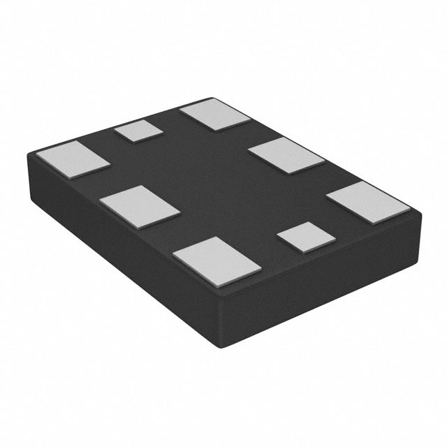
LMK61E2-I4SIAR uses a 7 mm × 5 mm, 8-pin QFM (SIA) package with wettable flank leads and an exposed thermal pad. Pin 1 is marked by a dot; top view orientation follows JEDEC standard.
| Pin/Terminal | Circuit Role | Design Meaning |
|---|---|---|
| OE (Pin 1) | Output Enable | LVCMOS input with internal pull-up; drives outputs to high-impedance when low - enables dynamic clock gating without external switches. |
| ADD (Pin 2) | I²C Address LSB | Configures I²C slave address (00/01/10) by tying to GND/VDD/floating - allows multiple devices on same bus without address conflict. |
| GND (Pin 3) | Ground Reference | Primary analog/digital ground return; connects directly to PCB ground plane under thermal pad for optimal noise immunity and thermal dissipation. |
| OUTP (Pin 4) | Differential Output + | Active-high side of universal differential pair; voltage swing and common-mode depend on selected output format (LVPECL/LVDS/HCSL). |
| OUTN (Pin 5) | Differential Output – | Active-low side of universal differential pair; matched routing required to maintain phase alignment and minimize skew (<1 ps). |
| VDD (Pin 6) | Supply Voltage | 3.3 V ± 5% analog/digital supply; requires local 100 nF ceramic decoupling adjacent to pin; powers internal LDOs and all functional blocks. |
| SDA (Pin 7) | I²C Data | Open-drain bidirectional bus line; requires external 2.2–10 kΩ pull-up to VDD - supports hot-plug configuration and multi-master arbitration. |
| SCL (Pin 8) | I²C Clock | Open-drain clock line; same pull-up requirement as SDA; defines I²C transaction timing and synchronizes register read/write operations. |
Key Features
| Feature | Design Value |
|---|---|
| Ultra-low jitter synthesis | 90 fs RMS typical (12 kHz–20 MHz) enables sub-100 ps timing margins in high-speed serial links and ADC/DAC sampling clocks. |
| Self-starting EEPROM | Factory-programmed 156.25 MHz LVPECL default eliminates boot-time configuration dependency - critical for unattended systems and firmware-first boot flows. |
| Multi-format output buffer | Single device replaces discrete LVPECL/LVDS/HCSL oscillators; reduces BOM count and layout complexity while maintaining signal integrity per interface standard. |
| Fine & coarse frequency margining | I²C-accessible tuning of oscillator core (fine) and output divider (coarse) supports DVT stress testing, margin validation, and yield optimization without hardware change. |
| Robust PSRR architecture | –70 dBc rejection of 50 kHz–1 MHz supply noise allows use with cost-effective switching regulators instead of ultra-low-noise LDOs, lowering system power cost. |
Applications
| 10G/25G Ethernet Line Cards | FPGA Reference Clocking |
|---|---|
Use Scenario: High-density switch/router line cards requiring synchronous 156.25 MHz or 161.1328125 MHz reference clocks for SERDES PHYs and packet processing ASICs. IC Role / Device Role / Timing Role: Primary low-jitter clock source for multi-lane 10G/25G KR/KR4 interfaces, meeting IEEE 802.3bj/802.3by jitter compliance limits. Use Value: 90 fs RMS jitter ensures <1 ps peak-to-peak deterministic jitter accumulation across 16 lanes, preserving bit error rate (BER) below 10⁻¹². |
Use Scenario: High-end Xilinx Versal or Intel Agilex FPGAs needing stable, programmable reference clocks for transceivers, memory controllers, and logic fabric. IC Role / Device Role / Timing Role: Configurable clock generator providing multiple synchronized frequencies (e.g., 100 MHz, 125 MHz, 156.25 MHz) from single device via I²C reprogramming. Use Value: EEPROM storage of custom configurations enables field-upgradable clock trees without FPGA reconfiguration or board redesign. |
| Medical Imaging Systems | Test & Measurement Equipment |
Use Scenario: Ultrasound beamformers and MRI gradient control systems demanding ultra-low phase noise clocks for precise analog signal sampling and timing synchronization. IC Role / Device Role / Timing Role: Low-phase-noise clock source for 14–16-bit ADCs and high-resolution DACs, operating at 100–200 MHz with sub-150 dBc/Hz floor at 10 MHz offset. Use Value: –165 dBc/Hz phase noise floor at 10 MHz offset (LVPECL) minimizes reciprocal mixing and preserves dynamic range in RF front-ends. |
Use Scenario: Oscilloscopes, spectrum analyzers, and arbitrary waveform generators requiring stable, low-jitter sampling clocks and trigger references. IC Role / Device Role / Timing Role: Programmable reference oscillator supporting multiple instrument modes (e.g., 100 MHz real-time sampling, 122.88 MHz digital downconversion). Use Value: ±50 ppm total tolerance and I²C margining allow traceable calibration verification and production test repeatability across environmental stress conditions. |
Equivalent & Alternatives
The following parts are listed as comparable options for similar programmable oscillator applications.
| Alternative Part | Technical Difference | Application Difference | Selection Advice |
|---|---|---|---|
| Si51211-D-GM | Lower max output frequency (800 MHz LVDS), higher typical jitter (120 fs RMS), no internal EEPROM - requires external configuration on power-up. | Lacks self-start capability; unsuitable for systems requiring guaranteed clock availability before firmware initialization. | Select if cost sensitivity outweighs EEPROM convenience and jitter budget allows ≥120 fs RMS. |
| AK210-01B-EVAL | Fixed-frequency (156.25 MHz only), no I²C interface, ±25 ppm tolerance, but lower jitter (75 fs RMS) and integrated 50 Ω terminations. | Not programmable; limited to single-output applications where frequency flexibility is unnecessary. | Select only for volume-deployed, fixed-clock designs where lowest possible jitter and simplified layout are prioritized over configurability. |
Compared with Si51211-D-GM and AK210-01B-EVAL, LMK61E2-I4SIAR uniquely balances field-programmability, EEPROM-based reliability, and sub-100 fs jitter - making it optimal for systems requiring post-manufacture clock tuning, firmware-agnostic boot, and multi-standard interoperability.
Availability
LMK61E2-I4SIAR is available at Aetrix Electronics and suitable for FPGA reference clocking, 10G/25G Ethernet line cards, and medical imaging systems requiring stable component supply, long-term lifecycle support, and consistent parametric performance across production batches.
Supply support for LMK61E2-I4SIAR includes scheduled delivery planning, volume procurement assistance, BOM continuity management, traceable sourcing, and lifecycle availability coordination for OEM customers, industrial embedded developers, connected-device designers, and electronics production programs.
Manufacturer
Texas Instruments is a global semiconductor company headquartered in Dallas, Texas, designing and manufacturing analog ICs, embedded processors, and programmable logic devices for industrial, automotive, and communications markets.
The LMK61E2-I4SIAR belongs to TI's Precision Clocks product line, engineered specifically for high-speed serial interface timing, data converter synchronization, and infrastructure equipment where jitter, stability, and programmability are critical system constraints.
FAQ
What is the default output configuration of LMK61E2-I4SIAR at power-up?
The LMK61E2-I4SIAR powers up with factory-programmed EEPROM settings delivering 156.25 MHz LVPECL output. This occurs without external I²C communication - the device starts generating a valid clock within 10 ms of VDD reaching 3.135 V, as specified in Section 5.12 of the datasheet.
Can LMK61E2-I4SIAR generate non-integer output frequencies like 161.1328125 MHz?
Yes. The LMK61E2-I4SIAR uses a fractional-N PLL with 22-bit numerator/denominator resolution to synthesize arbitrary frequencies within its 10–1000 MHz range. 161.1328125 MHz is explicitly validated in Section 5.18 with measured phase noise and jitter performance.
How does the ADD pin affect I²C communication?
The ADD pin sets the LSB of the 7-bit I²C slave address: tied to GND = 00, floating = 01, tied to VDD = 10. This allows up to three LMK61E2-I4SIAR devices on one I²C bus without address collision, as confirmed in Table 4-1 and Section 7.3.2 of the datasheet.
Is external termination required for LVPECL output operation?
Yes. LVPECL mode requires 150 Ω pull-down resistors from OUTP and OUTN to VCC–2 V (typically 1.3 V), as shown in Figure 6-1. These are not integrated and must be placed externally to meet differential swing (700–1200 mV) and common-mode (VDD–1.55 V) specifications.
LMK61E2-I4SIAR Specifications
- Product attributes
- Attribute value
- Manufacturer:
- Texas Instruments
- Package/Case:
- 8-SMD Module
- Series:
- LMK61E2
- Packaging:
- Bulk
- Product Status:
- Active
- Base Resonator:
- Silicon
- Type:
- VCXO
- Programmable Type:
- Factory-Configured
- Available Frequency Range:
- 10 MHz ~ 1 GHz
- Function:
- Enable/Disable
- Output:
- HCSL, LVDS, LVPECL
- Voltage - Supply:
- 3.3V
- Frequency Stability:
- -
- Frequency Stability (Total):
- ±50ppm
- Operating Temperature:
- -40°C ~ 85°C
- Spread Spectrum Bandwidth:
- -
- Current - Supply (Max):
- 208mA
- Ratings:
- -
- Mounting Type:
- Surface Mount
- Supplier Device Package:
- 8-QFM (7x5)
- Size / Dimension:
- 0.276" L x 0.197" W (7.00mm x 5.00mm)
- Height - Seated (Max):
- 0.045" (1.15mm)
LMK61E2-I4SIAR FAQ
1.How can I place an order for LMK61E2-I4SIAR through Aetrix?
Please submit a Request for Quotation (RFQ) for LMK61E2-I4SIAR on Aetrix. Our sales agent will provide a competitive quotation and guide you through the order confirmation once you accept the terms.
2.Are the price and stock information for LMK61E2-I4SIAR reliable?
The price and inventory of LMK61E2-I4SIAR are updated periodically and may fluctuate due to market conditions. Stock and pricing data are typically refreshed every 24 hours. Quotation validity for LMK61E2-I4SIAR is usually 5 days.
3.What payment methods are accepted for LMK61E2-I4SIAR?
We accept Wire Transfer, PayPal, Credit Card, Western Union, MoneyGram, and Escrow for LMK61E2-I4SIAR transactions.
Note: Certain payment methods may incur a processing fee.
4.How is shipping managed for LMK61E2-I4SIAR?
LMK61E2-I4SIAR orders can be shipped via leading logistics carriers, including DHL, UPS, FedEx, TNT, or Registered Mail.
Once your LMK61E2-I4SIAR order is processed, you will receive an email with the shipment details and tracking number.
Note: Tracking information may take up to 24 hours to appear. Express delivery typically takes 3–5 business days.
5.How can I obtain technical support or documentation for LMK61E2-I4SIAR?
For technical support, including LMK61E2-I4SIAR datasheets, pinout diagrams, or application guidance, please contact our engineering support team. They can provide detailed documentation and assistance for your LMK61E2-I4SIAR requirements.
6.How does Aetrix verify that LMK61E2-I4SIAR is sourced from the original manufacturer or authorized distributors?
All LMK61E2-I4SIAR products on Aetrix are procured from qualified distributors and authorized channels. Our dedicated quality assurance team conducts strict verification, including traceability checks and, if necessary, third-party testing. This ensures that LMK61E2-I4SIAR meets industry standards.
7.What is the process for return or replacement of LMK61E2-I4SIAR?
All LMK61E2-I4SIAR units undergo pre-shipment inspection (PSI). If there is an issue with LMK61E2-I4SIAR, returns or replacements are accepted under the following conditions:
1.Quantity discrepancies, incorrect items, or visible external defects (such as breakage or corrosion), acknowledged by Aetrix.
2.The issue is reported within 90 days of delivery.
3.The LMK61E2-I4SIAR part is unused and in its original packaging.
Return procedure for LMK61E2-I4SIAR:
1.Submit a request within 90 days.
2.Obtain a Return Material Authorization (RMA) from Aetrix.
LMK61E2-I4SIAR Tags
-
LMK61E2-SIAT
Texas Instruments
-
DSC8001CL5
Microchip Technology
-
LMK61E2BBA-SIAT
Texas Instruments
-
LMK61E2BAA-SIAT
Texas Instruments
-
DSC8001BL2
Microchip Technology
-7.00-mm-x-5.00-mm.jpg)
-
DSC1101NL3-PROGT
Microchip Technology
-
DSC8001AL2
Microchip Technology
-
DSC8101CI5
Microchip Technology
-
DSC8121AM2
Microchip Technology
-
DSC8123CI5
Microchip Technology
-
DSC6003HA3B-PROGT
Microchip Technology
-
DSC6101HA3B-PROGT
Microchip Technology
Tech Hub

An engineering guide to LED driver operation, constant-current and constant-voltage outputs, linear and switching topologies, dimming, IC selection, calculations, replacement compatibility, and fault c…

Operational amplifier guide covering op amp basics, feedback, ideal vs real op amps, common configurations, buffer circuits, offset, bias current, gain-bandwidth, slew rate, rail-to-rail limits and sel…

Jumper cables guide covering safe connection order, red and black clamp placement, final ground connection, cable gauge, length, clamp quality, copper vs CCA cables, jump starter comparison and battery…

LDO regulator guide covering low dropout voltage, power dissipation, thermal design, PSRR, output noise, capacitor stability, adjustable LDO circuits, LDO vs buck converter and datasheet selection chec…

Conditional Access Module guide covering CAM meaning, CI/CI+ interface, smart card authorization, DVB security workflow, TV and set-top box compatibility, internal electronics, ESD protection, connecto…

Guide to electronic component obsolescence covering EOL risk, PCN/PDN notices, last-time buy planning, replacement options, form-fit-function validation, counterfeit risk and BOM lifecycle management.

18650 battery guide covering lithium-ion cell basics, 3.6V/3.7V voltage, 4.2V charging, mAh and Wh capacity, protected cells, chargers, BMS, series-parallel packs, holders, welding and sourcing checks.…

Hall effect sensor guide covering working principle, linear and digital sensors, Arduino circuits, current sensing, speed detection, automotive applications, A3144 examples, signal filtering and datash…

Product Change Notification guide for electronic components, covering PCN meaning, PCN vs PDN/EOL, common change types, risk levels, form-fit-function review, engineering validation, BOM control, LTB/L…

A practical guide to blend door actuators, covering HVAC function, symptoms, location, AC and heater issues, reset and calibration, replacement cost, electrical diagnosis, compatibility checks, and rep…


