
 My Inquiry
 My Account


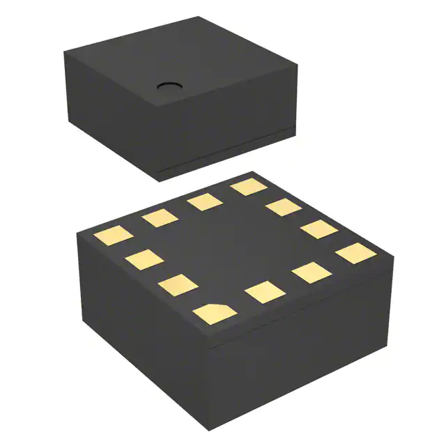
STMicroelectronics LSM303DLMTR
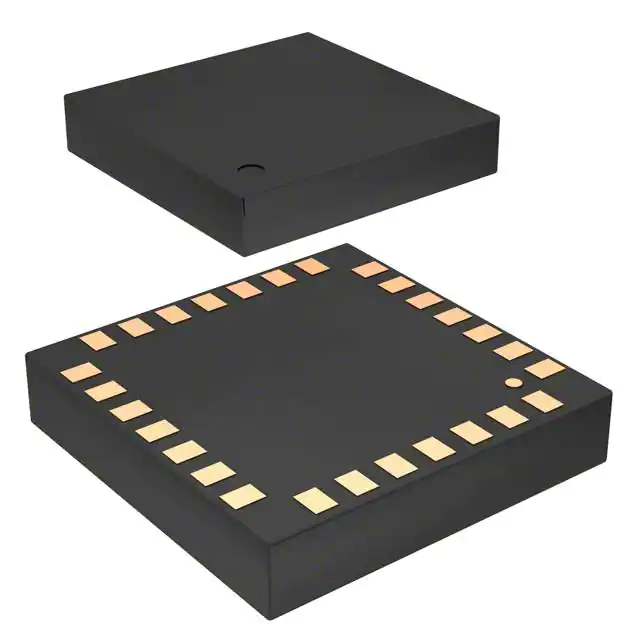
- Part No.:
- LSM303DLMTR
- Manufacturer:
- STMicroelectronics
- Category:
- IMUs (Inertial Measurement Units)
- Package:
- 28-VFLGA Module
- Datasheet:
-
 LSM303DLMTR.pdf
- Description:
- IMU ACCEL/MAG 3-AXIS I2C 28LGA
- Quantity:
- Payment:

- Shipping:

Inventory:4,451
Please send an inquiry. Send us your inquiry, and we will respond immediately.
Product details
Overview
LSM303DLMTR from STMicroelectronics is a system-in-package 3-axis accelerometer and 3-axis magnetometer sensor module designed for electronic compassing and motion sensing in portable devices. It delivers ±2 g/±4 g/±8 g dynamically selectable acceleration full-scale, ±1.3 to ±8.1 gauss magnetic full-scale, I²C interface (100 kHz / 400 kHz), dual programmable interrupt outputs, and 6D orientation detection - enabling tilt-compensated heading calculation in handheld navigation systems.
For engineers reviewing the LSM303DLMTR datasheet, LSM303DLMTR pinout, LSM303DLMTR application, or LSM303DLMTR equivalent, key selection considerations include independent power-down control per sensor, factory-trimmed offset and sensitivity, sleep-to-wakeup capability, magnetic cross-axis sensitivity (<1 %FS/gauss), and guaranteed operation from –40 °C to +85 °C in LGA-28 (5×5×1.0 mm) package.
Technical Context
The LSM303DLMTR integrates two independent sensor subsystems on a single die: a micromachined capacitive accelerometer with CMOS interface circuitry and a Hall-effect-based magnetometer with integrated set/reset (S/R) pulse generation for hysteresis compensation. Each sensor has dedicated I²C buses (SDA_A/SCL_A for accelerometer; SDA_M/SCL_M for magnetometer), allowing concurrent configuration and data acquisition without bus arbitration.
Its interrupt architecture supports inertial event detection (free-fall, motion, wakeup) and magnetic threshold crossing via two fully programmable interrupt generators (INT1, INT2), each with configurable thresholds, duration windows, and latching behavior. The DRDY_M pin provides asynchronous magnetic data-ready signaling, decoupling timing-critical magnetometer reads from accelerometer polling.
Key Specifications
| Parameter | Value and Actual Design Meaning |
|---|---|
| Acceleration FS | ±2 g / ±4 g / ±8 g - selectable via CTRL_REG4_A[4:3]; determines resolution (1 mg/digit to 3.9 mg/digit) and dynamic range for motion classification. |
| Magnetic FS | ±1.3 to ±8.1 gauss - set by CRB_REG_M[6:4]; higher ranges reduce resolution but improve immunity to external field saturation. |
| I²C Interface | Two independent buses: 100 kHz standard mode & 400 kHz fast mode - enables simultaneous accelerometer/magnetometer register access without contention. |
| Power Supply | Analog Vdd: 2.16–3.6 V; Digital Vdd_IO: 1.8 V - separates analog sensor core from digital I/O, minimizing noise coupling into sensitive magnetic measurements. |
| Operating Temp | –40 °C to +85 °C - validated across industrial temperature range; includes factory calibration at 25 °C with tempco specs (e.g., ±0.01 %/°C LA sensitivity drift). |
| Interrupt Outputs | INT1 & INT2 - independently configurable for free-fall, motion, 6D orientation, or magnetic threshold events; support push-pull or open-drain output modes. |
| Magnetic Resolution | 5 mgauss - enables sub-degree heading accuracy when combined with accelerometer tilt compensation in compass applications. |
Pinout & Package
LSM303DLMTR is housed in a 5 mm × 5 mm × 1.0 mm LGA-28 plastic land grid array package with exposed thermal pad (GND-connected). Pin assignment follows ST's standardized layout for dual-I²C sensor modules, supporting separate signal routing for accelerometer and magnetometer interfaces.
| Pin/Terminal | Circuit Role | Design Meaning |
|---|---|---|
| 6, 22, 23, 28 | Vdd / Vdd_IO / GND connections | Dedicated analog supply (Vdd), I/O supply (Vdd_IO = 1.8 V), and multiple GND pins minimize ground bounce between sensor domains. |
| 24, 25 | SCL_A / SDA_A | Isolated I²C bus for accelerometer - allows independent clock stretching and avoids interference from magnetometer DRDY_M transitions. |
| 18, 19, 20 | DRDY_M / SDA_M / SCL_M | Magnetometer data-ready flag + dedicated I²C bus - enables precise timing alignment of magnetic samples relative to motion events. |
| 26, 27 | INT1 / INT2 | Configurable open-drain interrupt outputs - drive external MCU GPIOs to trigger low-power wakeups or real-time motion logging without polling. |
| 12, 15, 16 | SET2 / C1 / SET1 | Set/Reset capacitor terminals - enable internal S/R pulse generation to cancel residual magnetization in magnetoresistive elements, ensuring stable zero-field baseline. |
Key Features
| Feature | Design Value |
|---|---|
| Independent sensor power control | Accelerometer and magnetometer can be placed in power-down mode separately - reduces system standby current to <1 µA when only one sensor is active. |
| Factory-calibrated offset & sensitivity | Zero-g offset accuracy ±60 mg (typ.), magnetic gain trimmed per axis - eliminates need for end-user calibration in cost-sensitive consumer designs. |
| Sleep-to-wakeup function | Accelerometer wakes device from ultra-low-power state upon configurable motion threshold - enables battery-efficient always-on gesture detection. |
| 6D orientation detection | Identifies device position (up/down/left/right/front/back) using acceleration vector - used for auto-rotating UIs and gaming input without requiring gyroscope fusion. |
| Magnetic cross-axis sensitivity | ≤1 %FS/gauss - ensures minimal crosstalk between orthogonal magnetic axes, critical for accurate heading computation in compact PCB layouts. |
Applications
| Electronic Compass | Smartphone Display Rotation |
|---|---|
|
Use Scenario: Tilt-compensated heading calculation in GPS-denied indoor environments using fused accelerometer and magnetometer data. IC Role / Device Role / Timing Role: Accelerometer provides pitch/roll angles; magnetometer measures Earth's magnetic field vector; both sampled synchronously via independent I²C buses. Use Value: Achieves <2° heading error over full tilt range due to factory-trimmed magnetic gain and low cross-axis sensitivity. |
Use Scenario: Automatic screen orientation switching during device rotation, triggered by gravity vector changes. IC Role / Device Role / Timing Role: Accelerometer detects 6D orientation state; INT1 asserts on position change; MCU reads updated axis data without continuous polling. Use Value: Reduces average system power by >90% vs. polling-based solutions via sleep-to-wakeup and interrupt-driven updates. |
| Gaming Motion Input | Impact Logging in Wearables |
|
Use Scenario: Real-time gesture recognition (e.g., swing, shake, tap) in AR/VR controllers and fitness trackers. IC Role / Device Role / Timing Role: Dual interrupt generators detect free-fall (swing start) and motion (acceleration peak); DRDY_M aligns magnetic reference frame for motion context. Use Value: Enables sub-50 ms latency between physical gesture and system response using hardware-accelerated event detection. |
Use Scenario: Detection and timestamping of mechanical shocks (>5 g) in sports sensors or industrial wearables. IC Role / Device Role / Timing Role: Accelerometer configured in ±8 g mode with programmable INT2 threshold; latched interrupt preserves event record during MCU sleep. Use Value: Captures transient impacts with ±60 mg zero-g offset stability, eliminating false triggers from thermal drift or PCB flex. |
Equivalent & Alternatives
The following parts are listed as comparable options for similar 3-axis accelerometer + 3-axis magnetometer applications.
| Alternative Part | Technical Difference | Application Difference | Selection Advice |
|---|---|---|---|
| BNO055 | Fused 9-DOF AHRS with embedded sensor fusion MCU; requires no host-side quaternion math. | Higher BOM cost; eliminates need for external motion processing but adds fixed firmware behavior. | Select when rapid time-to-market for orientation output is prioritized over raw sensor flexibility. |
| LSM9DS1 | Includes integrated 3-axis gyroscope; shares same LGA-24 package footprint but different pinout and register map. | Enables full IMU functionality; magnetometer FS limited to ±4 gauss (vs. ±8.1 gauss in LSM303DLMTR). | Select when angular rate measurement is required alongside compassing, accepting trade-off in magnetic dynamic range. |
Compared with BNO055 and LSM9DS1, the LSM303DLMTR offers superior magnetic full-scale (±8.1 gauss) and independent dual-I²C control - making it optimal for high-accuracy compassing where external fusion algorithms demand maximum raw sensor fidelity and timing autonomy.
Availability
LSM303DLMTR is available at Aetrix Electronics and suitable for electronic compassing, smartphone display rotation, gaming motion input, and impact logging applications requiring stable component supply across industrial temperature ranges and long production lifecycles.
Supply support for LSM303DLMTR includes scheduled delivery planning, volume procurement assistance, BOM continuity management, traceable sourcing, and lifecycle availability coordination for OEM customers, industrial embedded developers, connected-device designers, and electronics production programs.
Manufacturer
STMicroelectronics is a global semiconductor leader specializing in MEMS sensors, microcontrollers, and power management ICs, with manufacturing facilities certified to ISO 9001 and IATF 16949 standards.
The LSM303DLMTR belongs to ST's iNEMO™ family of intelligent inertial modules, engineered specifically for low-power, high-accuracy motion sensing in space-constrained portable electronics - emphasizing factory calibration, thermal stability, and interrupt-driven efficiency.
FAQ
What is the purpose of the SET1/SET2/C1 pins?
SET1, SET2, and C1 connect external capacitors to enable the magnetometer's internal Set/Reset (S/R) pulse generator. This circuit applies controlled magnetic pulses to cancel residual magnetization in the sensing elements, restoring baseline accuracy after exposure to strong fields (>20 gauss) and maintaining long-term zero-field stability.
Can the accelerometer and magnetometer operate simultaneously on shared I²C lines?
No - the LSM303DLMTR uses physically separate I²C buses: SDA_A/SCL_A for the accelerometer and SDA_M/SCL_M for the magnetometer. This eliminates bus contention, allows independent clock rates (e.g., 400 kHz for mag, 100 kHz for accel), and prevents DRDY_M transitions from disrupting accelerometer register reads.
How does the 6D orientation detection work without a gyroscope?
The 6D detection logic evaluates the static acceleration vector magnitude and quadrant distribution across three axes. When the dominant gravity component exceeds ±0.9 g in any single axis, the device asserts orientation status bits in STATUS_REG_A - enabling UI rotation or mode switching based solely on tilt, with no integration or drift concerns.
What is the significance of the "ECOPACK®" designation?
ECOPACK® indicates ST's proprietary eco-friendly packaging technology: halogen-free materials, lead-free terminations, and RoHS/REACH compliance. For the LSM303DLMTR, this means the LGA-28 package uses matte tin finishes and green molding compound - meeting environmental requirements for consumer and medical electronics without performance compromise.
LSM303DLMTR Specifications
- Product attributes
- Attribute value
- Manufacturer:
- STMicroelectronics
- Series:
- -
- Package/Case:
- 28-VFLGA Module
- Packaging:
- Tape & Reel (TR)
- Product Status:
- Obsolete
- Sensor Type:
- Accelerometer, Magnetometer, 6 Axis
- Output Type:
- I2C
- Operating Temperature:
- -40°C ~ 85°C
- Grade:
- -
- Qualification:
- -
- Supplier Device Package:
- 28-LGA (5x5)
- Mounting Type:
- Surface Mount
LSM303DLMTR FAQ
1.How can I place an order for LSM303DLMTR through Aetrix?
Please submit a Request for Quotation (RFQ) for LSM303DLMTR on Aetrix. Our sales agent will provide a competitive quotation and guide you through the order confirmation once you accept the terms.
2.Are the price and stock information for LSM303DLMTR reliable?
The price and inventory of LSM303DLMTR are updated periodically and may fluctuate due to market conditions. Stock and pricing data are typically refreshed every 24 hours. Quotation validity for LSM303DLMTR is usually 5 days.
3.What payment methods are accepted for LSM303DLMTR?
We accept Wire Transfer, PayPal, Credit Card, Western Union, MoneyGram, and Escrow for LSM303DLMTR transactions.
Note: Certain payment methods may incur a processing fee.
4.How is shipping managed for LSM303DLMTR?
LSM303DLMTR orders can be shipped via leading logistics carriers, including DHL, UPS, FedEx, TNT, or Registered Mail.
Once your LSM303DLMTR order is processed, you will receive an email with the shipment details and tracking number.
Note: Tracking information may take up to 24 hours to appear. Express delivery typically takes 3–5 business days.
5.How can I obtain technical support or documentation for LSM303DLMTR?
For technical support, including LSM303DLMTR datasheets, pinout diagrams, or application guidance, please contact our engineering support team. They can provide detailed documentation and assistance for your LSM303DLMTR requirements.
6.How does Aetrix verify that LSM303DLMTR is sourced from the original manufacturer or authorized distributors?
All LSM303DLMTR products on Aetrix are procured from qualified distributors and authorized channels. Our dedicated quality assurance team conducts strict verification, including traceability checks and, if necessary, third-party testing. This ensures that LSM303DLMTR meets industry standards.
7.What is the process for return or replacement of LSM303DLMTR?
All LSM303DLMTR units undergo pre-shipment inspection (PSI). If there is an issue with LSM303DLMTR, returns or replacements are accepted under the following conditions:
1.Quantity discrepancies, incorrect items, or visible external defects (such as breakage or corrosion), acknowledged by Aetrix.
2.The issue is reported within 90 days of delivery.
3.The LSM303DLMTR part is unused and in its original packaging.
Return procedure for LSM303DLMTR:
1.Submit a request within 90 days.
2.Obtain a Return Material Authorization (RMA) from Aetrix.
LSM303DLMTR Tags

-
BMI323
Bosch Sensortec
-
ICM-42670-P
TDK InvenSense
-
ICM-42605
TDK InvenSense

-
LSM6DSO32TR
STMicroelectronics
-
LSM6DSOTR
STMicroelectronics
-
LSM6DSVTR
STMicroelectronics
-
LSM6DSRTR
STMicroelectronics
-
BMI270
Bosch Sensortec
-
LSM6DSOXTR
STMicroelectronics
-
LSM6DSV16XTR
STMicroelectronics
-
LSM6DSO16ISTR
STMicroelectronics
-
LSM303AGRTR
STMicroelectronics
Tech Hub

A practical engineering and sourcing framework covering lifecycle verification, lifetime-buy calculations, replacement qualification, supplier checks and counterfeit-risk controls.

TTL and CMOS logic families differ in thresholds, loading, output drive, power and timing. This engineering guide compares 74HC and 74HCT, calculates noise margins and checks 3.3 V/5 V compatibility.

A practical engineering guide to 3.3V and 5V logic compatibility, input thresholds, resistor dividers, translator ICs, MOSFET level shifting, I2C pull-ups, timing limits and power-sequencing risks.

The 74HC595 uses push-pull logic outputs, while the TPIC6B595 uses 50 V open-drain DMOS sinks for higher-power loads. This guide compares timing, current limits, 3.3 V interfacing, load wiring, thermal…

The 74HC595 converts serial data into eight stable parallel outputs. This guide covers pin functions, shift and storage timing, OE and MR behavior, drive-current limits, cascading, voltage compatibilit…

A technical comparison of level-sensitive latches and edge-triggered flip-flops, covering timing windows, setup and hold limits, master–slave operation, time borrowing, race-through, HDL inference and…

A D latch stores one bit while Enable controls when data can pass. This reference covers gate-level operation, truth tables, transparency, setup and hold timing, LE versus OE, common ICs and practical …

An SR latch stores one bit through cross-coupled feedback. This engineering reference covers NOR and NAND implementations, truth tables, forbidden-state recovery, gated operation, switch debouncing, fa…

Latch circuits retain one bit through feedback. This technical reference covers SR and D latches, truth tables, transparency, timing limits, latch-versus-flip-flop behavior, applications and common log…

An engineering guide to LED driver operation, constant-current and constant-voltage outputs, linear and switching topologies, dimming, IC selection, calculations, replacement compatibility, and fault c…


