
 My Inquiry
 My Account


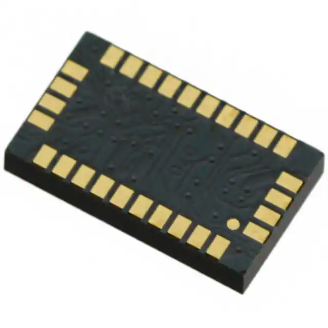
STMicroelectronics LSM330DLTR
- Part No.:
- LSM330DLTR
- Manufacturer:
- STMicroelectronics
- Category:
- IMUs (Inertial Measurement Units)
- Package:
- 28-TFLGA Module
- Datasheet:
-
 LSM330DLTR.pdf
- Description:
- IMU ACCEL/GYRO I2C/SPI 28LGA
- Quantity:
- Payment:

- Shipping:

Inventory:1,513
Please send an inquiry. Send us your inquiry, and we will respond immediately.
Product details
Overview
LSM330DLTR from STMicroelectronics is a system-in-package 6-axis inertial measurement unit (IMU) integrating a 3D digital accelerometer and a 3D digital gyroscope. It delivers ±2g/±4g/±8g/±16g acceleration full-scale ranges and ±250/±500/±2000 dps angular rate full-scale ranges, with dual SPI/I²C serial interfaces and programmable motion interrupts. It is used in GPS navigation systems for dead-reckoning augmentation and orientation tracking.
For engineers reviewing the LSM330DLTR datasheet, LSM330DLTR pinout, LSM330DLTR application, or LSM330DLTR equivalent, key selection criteria include its dual-sensor integration, independent power modes per sensor, 28-pin LGA package footprint, and factory-trimmed sensitivity matching between accelerometer and gyroscope channels.
Technical Context
The LSM330DLTR implements two independent sensing subsystems on a single die: a micromachined capacitive accelerometer and a vibrating structure gyroscope, both interfaced via shared CMOS signal-conditioning circuitry. Each sensor has dedicated control registers (e.g., CTRL_REG1_A/G), FIFO buffers, and interrupt generators.
It supports simultaneous operation of both sensors at configurable output data rates (ODR), with selectable high-pass filtering on accelerometer axes and user-defined interrupt thresholds for free-fall, click, and motion detection events. The device operates across –40 °C to +85 °C and uses separate analog (2.4–3.6 V) and digital I/O (1.8 V) supply rails.
Key Specifications
| Parameter | Value and Actual Design Meaning |
|---|---|
| Supply Voltage (Analog) | 2.4 V to 3.6 V - powers MEMS sensing elements and analog front-end; stable operation requires low-noise regulation. |
| Supply Voltage (Digital I/O) | 1.8 V - matches low-voltage host microcontrollers; no level-shifting needed for 1.8 V logic domains. |
| Acceleration Full-Scale Range | ±2g / ±4g / ±8g / ±16g - software-selectable per axis; enables trade-off between resolution and dynamic range in motion capture. |
| Angular Rate Full-Scale Range | ±250 / ±500 / ±2000 dps - selectable per gyroscope axis; higher ranges support fast rotational motion without saturation. |
| Communication Interface | SPI (4-wire or 3-wire) and I²C - dual-protocol support simplifies integration into diverse host architectures without external bridge ICs. |
| Interrupt Outputs | Two dedicated pins (INT1, INT2) - configurable for free-fall, motion detection, FIFO threshold, or data-ready events; reduces host polling overhead. |
| Operating Temperature | –40 °C to +85 °C - validated for industrial and automotive cabin environments; no derating required within this range. |
Pinout & Package
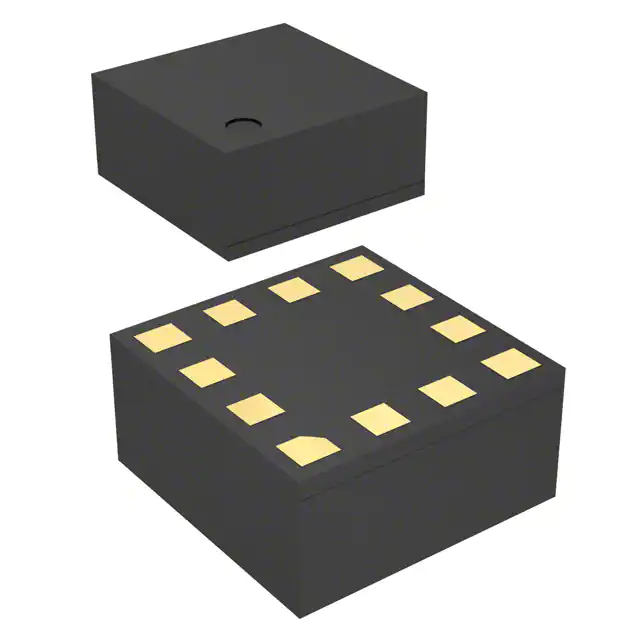
LSM330DLTR is housed in a 28-pin plastic land grid array (LGA) package measuring 7.5 mm × 4.4 mm × 1.1 mm. This compact, surface-mount package supports automated assembly and provides robust mechanical stability for handheld and portable applications.
| Pin/Terminal | Circuit Role | Design Meaning |
|---|---|---|
| VDD | Analog supply input | Connects to 2.4–3.6 V regulated analog rail; decoupling capacitor required near pin for noise suppression. |
| VDD_IO | Digital I/O supply | Supplies 1.8 V to digital interface logic; must be stable and isolated from noisy digital ground planes. |
| GND | Ground reference | Common analog/digital ground plane connection; low-impedance return path critical for sensor accuracy. |
| SCL/SPC | I²C clock / SPI clock | Multiplexed pin: SCL in I²C mode; SPC in SPI mode - mode selected by hardware configuration or boot sequence. |
| SDA/SDI | I²C data / SPI data in | Multiplexed bidirectional pin: open-drain I²C data line; MOSI-equivalent SPI input during write operations. |
| SDO/SA0 | SPI data out / I²C address LSB | Multiplexed pin: outputs SPI data; sets LSB of I²C slave address when used as SA0 in I²C mode. |
| INT1 | Programmable interrupt output #1 | Active-low open-drain output; configured via INT1_CFG_A/G registers for motion, free-fall, FIFO, or data-ready events. |
| INT2 | Programmable interrupt output #2 | Active-low open-drain output; independently configurable for complementary or redundant event signaling. |
Key Features
| Feature | Design Value |
|---|---|
| Independent sensor power control | Accelerometer and gyroscope can be placed in low-power or power-down mode separately - enables fine-grained power budgeting in battery-powered devices. |
| Factory-calibrated sensitivity matching | Trimmed CMOS interface circuitry compensates for MEMS process variation - ensures consistent scale factor alignment between accelerometer and gyroscope outputs. |
| 6D orientation detection | Combines 3-axis acceleration and 3-axis angular rate data to resolve device tilt and rotation state - eliminates need for external fusion algorithm in basic orientation use cases. |
| Programmable high-pass filter (accelerometer) | Configurable cutoff frequencies enable removal of gravity component from motion signals - essential for vibration monitoring and impact logging. |
| Embedded FIFO buffer (per sensor) | Separate 32-level FIFOs for accelerometer and gyroscope - reduces host CPU load by batching data reads and minimizing I²C/SPI transaction frequency. |
Applications
| GPS Navigation Systems | Impact Recognition and Logging |
|---|---|
|
Use Scenario: Indoor or tunnel environments where GNSS signal is lost or degraded. IC Role / Device Role / Timing Role: Provides dead-reckoning inputs (acceleration + angular rate) to maintain position and heading estimates between GNSS updates. Use Value: Enables continuous navigation without reliance on satellite lock; leverages 6D motion data to correct drift in pedestrian and vehicle tracking. |
Use Scenario: Industrial equipment or consumer electronics subjected to mechanical shock events. IC Role / Device Role / Timing Role: Detects and timestamps high-g impacts using programmable free-fall and motion-detection interrupts. Use Value: Captures peak acceleration magnitude and direction without host CPU intervention; supports predictive maintenance and warranty analytics. |
| Gaming and VR Input Devices | Vibration Monitoring and Compensation |
|
Use Scenario: Motion-controlled game controllers or VR headsets requiring real-time 6DoF tracking. IC Role / Device Role / Timing Role: Delivers synchronized, low-latency accelerometer and gyroscope samples to host MCU for sensor fusion. Use Value: Achieves sub-10 ms end-to-end latency with configurable ODR up to 950 Hz - critical for immersive responsiveness and motion sickness reduction. |
Use Scenario: Precision machinery or robotics where structural resonance affects performance. IC Role / Device Role / Timing Role: Measures broadband vibration spectra using high-resolution acceleration data and temperature-compensated gyroscope feedback. Use Value: Enables closed-loop compensation algorithms by providing correlated 6-axis motion data sampled at matched timing intervals. |
Equivalent & Alternatives
The following parts are listed as comparable options for similar 6-axis IMU applications.
| Alternative Part | Technical Difference | Application Difference | Selection Advice |
|---|---|---|---|
| LSM6DS3TR-C | Integrated digital motion processor (DMP), lower power (0.65 mA typical), smaller 3.2 × 2.5 mm LGA-14 package, no separate analog/digital supplies. | Targets always-on wearable and IoT edge nodes; lacks standalone analog supply flexibility for legacy designs. | Choose for new ultra-low-power designs requiring embedded sensor fusion; avoid if analog supply separation or legacy register compatibility is required. |
| ICM-20602 | Higher gyroscope sensitivity (16.4 mdps/LSB), integrated temperature sensor, supports auxiliary I²C master mode for magnetometer daisy-chaining. | Better suited for AHRS and drone stabilization where precise angular rate resolution and multi-sensor synchronization matter. | Prefer when magnetometer integration or tighter angular rate quantization is needed; verify interrupt architecture compatibility with existing firmware. |
Compared with LSM6DS3TR-C and ICM-20602, the LSM330DLTR offers unique dual-supply operation and mature register-level compatibility with earlier ST IMUs, making it suitable for cost-sensitive industrial upgrades where analog domain isolation and register mapping continuity are design constraints.
Availability
LSM330DLTR is available at Aetrix Electronics and suitable for GPS navigation systems, impact recognition and logging, gaming and virtual reality input devices, and vibration monitoring and compensation requiring stable component supply across extended product lifecycles.
Supply support for LSM330DLTR includes scheduled delivery planning, volume procurement assistance, BOM continuity management, traceable sourcing, and lifecycle availability coordination for OEM customers, industrial embedded developers, connected-device designers, and electronics production programs.
Manufacturer
STMicroelectronics is a global semiconductor leader headquartered in Geneva, Switzerland, specializing in MEMS sensors, microcontrollers, power management, and automotive ICs.
The LSM330DLTR belongs to ST's legacy inertial sensor module family, designed for high-accuracy 6-axis motion sensing in portable and industrial applications where co-location of accelerometer and gyroscope improves alignment stability and reduces board space.
FAQ
What is the maximum SPI clock frequency supported by the LSM330DLTR?
The LSM330DLTR supports SPI clock frequencies up to 10 MHz in standard 4-wire mode and 4 MHz in 3-wire mode, as specified in Table 6 of the datasheet. These values ensure reliable communication while maintaining timing margins across voltage and temperature extremes.
Does the LSM330DLTR require external passive components for basic operation?
Yes - a 100 nF ceramic capacitor is required between VDD and GND, and another 100 nF capacitor between VDD_IO and GND, placed as close as possible to their respective pins. No external pull-ups are needed for I²C if internal pull-ups are enabled via CTRL_REG3_A register bit 7.
Can the accelerometer and gyroscope operate at different output data rates (ODRs)?
Yes - each sensor has independent ODR configuration registers (e.g., CTRL_REG1_A for accelerometer, CTRL_REG1_G for gyroscope). This allows asymmetric sampling, such as 100 Hz for accelerometer-based tilt detection and 200 Hz for gyroscope-based rotation tracking, optimizing power and bandwidth.
Is the LSM330DLTR RoHS and REACH compliant?
Yes - the LSM330DLTR is ECOPACK® certified, RoHS-compliant, and "Green" compliant per the manufacturer's documentation (Doc ID 022018 Rev 1, page 1). It contains no lead, mercury, cadmium, hexavalent chromium, PBB, or PBDE above threshold limits.
LSM330DLTR Specifications
- Product attributes
- Attribute value
- Manufacturer:
- STMicroelectronics
- Series:
- -
- Package/Case:
- 28-TFLGA Module
- Packaging:
- Tape & Reel (TR)
- Product Status:
- Obsolete
- Sensor Type:
- Accelerometer, Gyroscope, 6 Axis
- Output Type:
- I2C, SPI
- Operating Temperature:
- -40°C ~ 85°C
- Grade:
- -
- Qualification:
- -
- Supplier Device Package:
- 28-LGA (7.5x4.4)
- Mounting Type:
- Surface Mount
LSM330DLTR FAQ
1.How can I place an order for LSM330DLTR through Aetrix?
Please submit a Request for Quotation (RFQ) for LSM330DLTR on Aetrix. Our sales agent will provide a competitive quotation and guide you through the order confirmation once you accept the terms.
2.Are the price and stock information for LSM330DLTR reliable?
The price and inventory of LSM330DLTR are updated periodically and may fluctuate due to market conditions. Stock and pricing data are typically refreshed every 24 hours. Quotation validity for LSM330DLTR is usually 5 days.
3.What payment methods are accepted for LSM330DLTR?
We accept Wire Transfer, PayPal, Credit Card, Western Union, MoneyGram, and Escrow for LSM330DLTR transactions.
Note: Certain payment methods may incur a processing fee.
4.How is shipping managed for LSM330DLTR?
LSM330DLTR orders can be shipped via leading logistics carriers, including DHL, UPS, FedEx, TNT, or Registered Mail.
Once your LSM330DLTR order is processed, you will receive an email with the shipment details and tracking number.
Note: Tracking information may take up to 24 hours to appear. Express delivery typically takes 3–5 business days.
5.How can I obtain technical support or documentation for LSM330DLTR?
For technical support, including LSM330DLTR datasheets, pinout diagrams, or application guidance, please contact our engineering support team. They can provide detailed documentation and assistance for your LSM330DLTR requirements.
6.How does Aetrix verify that LSM330DLTR is sourced from the original manufacturer or authorized distributors?
All LSM330DLTR products on Aetrix are procured from qualified distributors and authorized channels. Our dedicated quality assurance team conducts strict verification, including traceability checks and, if necessary, third-party testing. This ensures that LSM330DLTR meets industry standards.
7.What is the process for return or replacement of LSM330DLTR?
All LSM330DLTR units undergo pre-shipment inspection (PSI). If there is an issue with LSM330DLTR, returns or replacements are accepted under the following conditions:
1.Quantity discrepancies, incorrect items, or visible external defects (such as breakage or corrosion), acknowledged by Aetrix.
2.The issue is reported within 90 days of delivery.
3.The LSM330DLTR part is unused and in its original packaging.
Return procedure for LSM330DLTR:
1.Submit a request within 90 days.
2.Obtain a Return Material Authorization (RMA) from Aetrix.
LSM330DLTR Tags

-
BMI323
Bosch Sensortec
-
ICM-42670-P
TDK InvenSense
-
ICM-42605
TDK InvenSense

-
LSM6DSO32TR
STMicroelectronics
-
LSM6DSOTR
STMicroelectronics
-
LSM6DSVTR
STMicroelectronics
-
LSM6DSRTR
STMicroelectronics
-
BMI270
Bosch Sensortec
-
LSM6DSOXTR
STMicroelectronics
-
LSM6DSV16XTR
STMicroelectronics
-
LSM6DSO16ISTR
STMicroelectronics
-
LSM303AGRTR
STMicroelectronics
Tech Hub

A practical engineering and sourcing framework covering lifecycle verification, lifetime-buy calculations, replacement qualification, supplier checks and counterfeit-risk controls.

TTL and CMOS logic families differ in thresholds, loading, output drive, power and timing. This engineering guide compares 74HC and 74HCT, calculates noise margins and checks 3.3 V/5 V compatibility.

A practical engineering guide to 3.3V and 5V logic compatibility, input thresholds, resistor dividers, translator ICs, MOSFET level shifting, I2C pull-ups, timing limits and power-sequencing risks.

The 74HC595 uses push-pull logic outputs, while the TPIC6B595 uses 50 V open-drain DMOS sinks for higher-power loads. This guide compares timing, current limits, 3.3 V interfacing, load wiring, thermal…

The 74HC595 converts serial data into eight stable parallel outputs. This guide covers pin functions, shift and storage timing, OE and MR behavior, drive-current limits, cascading, voltage compatibilit…

A technical comparison of level-sensitive latches and edge-triggered flip-flops, covering timing windows, setup and hold limits, master–slave operation, time borrowing, race-through, HDL inference and…

A D latch stores one bit while Enable controls when data can pass. This reference covers gate-level operation, truth tables, transparency, setup and hold timing, LE versus OE, common ICs and practical …

An SR latch stores one bit through cross-coupled feedback. This engineering reference covers NOR and NAND implementations, truth tables, forbidden-state recovery, gated operation, switch debouncing, fa…

Latch circuits retain one bit through feedback. This technical reference covers SR and D latches, truth tables, transparency, timing limits, latch-versus-flip-flop behavior, applications and common log…

An engineering guide to LED driver operation, constant-current and constant-voltage outputs, linear and switching topologies, dimming, IC selection, calculations, replacement compatibility, and fault c…


