
 My Inquiry
 My Account


Analog Devices Inc. LTC3588EMSE-1#PBF
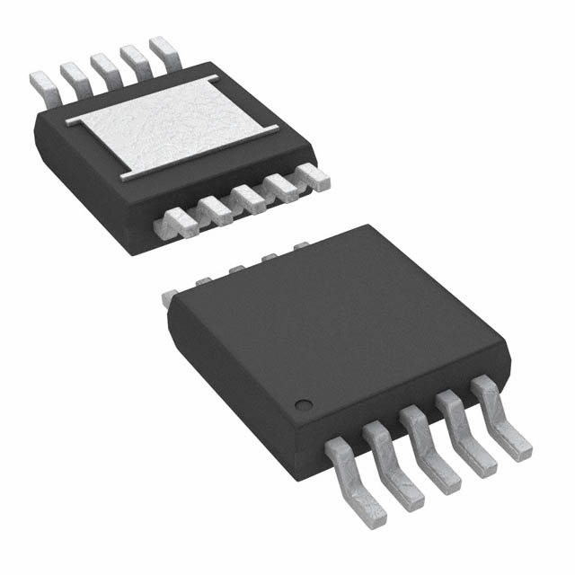
- Part No.:
- LTC3588EMSE-1#PBF
- Manufacturer:
- Analog Devices Inc.
- Category:
- Power Management - Specialized
- Package:
- 10-TFSOP, 10-MSOP (0.118", 3.00mm Width) Exposed Pad
- Datasheet:
-
 LTC3588EMSE-1#PBF.pdf
- Description:
- IC ENERGY HARVESTING PSU 10MSOP
- Quantity:
- Payment:

- Shipping:

Inventory:186
Please send an inquiry. Send us your inquiry, and we will respond immediately.
Product details
Overview
LTC3588EMSE-1#PBF from Analog Devices (formerly Linear Technology) is an ultralow-quiescent-current energy harvesting power supply IC integrating a low-loss full-wave bridge rectifier and a hysteretic synchronous buck regulator. It operates from 2.7V–20V input, delivers up to 100mA continuous output at pin-selectable voltages (1.8V/2.5V/3.3V/3.6V), and features 450nA UVLO quiescent current - optimized for piezoelectric, electro-mechanical, and low-power ambient energy sources in wireless sensor nodes.
For engineers reviewing the LTC3588EMSE-1#PBF datasheet, LTC3588EMSE-1#PBF pinout, LTC3588EMSE-1#PBF application, or LTC3588EMSE-1#PBF equivalent, key selection criteria include input voltage hysteresis window (≥1.0V), 950nA regulation quiescent current, integrated 20V input shunt protection, PGOOD logic-level output referenced to VOUT, and eMSOP-10 package compatibility with nanopower PCB layouts.
Technical Context
The LTC3588EMSE-1#PBF implements a two-stage energy harvesting architecture: first, a differential PZ1/PZ2 full-wave bridge rectifies AC inputs (e.g., piezoelectric transducers) into a DC reservoir on VIN; second, a hysteretic buck converter transfers stored energy to VOUT only when VIN exceeds a programmable UVLO rising threshold (3.77V–5.05V depending on output voltage). This eliminates continuous switching losses.
Internal rail generation provides CAP (VIN–4.8V) for PMOS gate drive and VIN2 (4.8V above GND, clamped to VIN if <4.8V) for NMOS drive and D0/D1 logic reference. Sleep mode reduces total input quiescent current to 950nA while maintaining regulation via VOUT sensing and wake-up based on ±12mV hysteresis around the selected output voltage.
Key Specifications
| Parameter | Value and Actual Design Meaning |
|---|---|
| Input Voltage Range | 2.7V to 20V - supports high-voltage energy storage on input capacitor; internal 20V shunt clamp prevents overvoltage damage. |
| Output Voltage Options | 1.8V / 2.5V / 3.3V / 3.6V - selected by D0/D1 logic pins; each has dedicated UVLO thresholds and ±12mV sleep hysteresis. |
| Max Continuous Output Current | 100mA - delivered by synchronous buck with 260mA peak switch current; enables burst loads in wireless sensor applications. |
| Quiescent Current (UVLO) | 450nA typical - allows multi-hour energy accumulation from µA-level piezoelectric sources before enabling buck operation. |
| Quiescent Current (Regulation) | 950nA typical - minimizes standby loss while maintaining regulated VOUT with no load; critical for multi-year batteryless operation. |
| Input Protective Shunt | 20V clamp with 25mA max pull-down - safely dissipates excess energy during high-amplitude vibration events. |
| PGOOD Threshold | 92% of selected VOUT - open-drain logic-high signal referenced to VOUT rail; used to enable microcontrollers after stable regulation. |
Pinout & Package
Package: 10-Lead Plastic eMSOP (MSE), 3mm × 3mm footprint, exposed pad (Pin 11) connected to GND. Thermal resistance θJA = 45°C/W.
| Pin/Terminal | Circuit Role | Design Meaning |
|---|---|---|
| PZ1, PZ2 | Differential AC input terminals | Connect to piezoelectric element; form full-wave bridge rectifier - no external diodes required. |
| VIN | Rectified input rail / energy reservoir node | Stores harvested energy; internally clamped to 20V; supplies buck input and CAP/VIN2 rails. |
| CAP | PMOS gate drive rail | Internally regulated at VIN – 4.8V; requires 1µF bypass to VIN; not for external use. |
| SW | Buck switch node | Drives external inductor (≥10µH); connects between SW and VOUT; carries pulsed current up to 260mA. |
| VOUT | Regulated output sense & power node | Feedback point for buck regulation; supplies load; PGOOD referenced to this rail. |
| VIN2 | NMOS gate drive & D0/D1 logic rail | Internally regulated at 4.8V above GND (clamped to VIN if <4.8V); requires 4.7µF bypass to GND. |
| D0, D1 | Output voltage select bits | Logic inputs tied to GND or VIN2; determine VOUT (1.8V/2.5V/3.3V/3.6V) per Table 1 in datasheet. |
| PGOOD | Power-good status indicator | Open-drain output pulled high to VOUT when VOUT ≥ 92% of target; signals system readiness. |
| GND (EP) | Ground reference & thermal path | Exposed pad (Pin 11) must be soldered to PCB ground plane via multiple vias for thermal and electrical integrity. |
Key Features
| Feature | Design Value |
|---|---|
| Integrated full-wave bridge rectifier | Eliminates 4 external diodes; 400mV typical drop at 10µA; supports single-ended DC input via PZ1/PZ2. |
| Ultralow UVLO quiescent current | 450nA enables efficient energy harvesting from sources delivering <1µW average power. |
| Hysteretic buck regulation | No external compensation needed; self-starting; maintains regulation with 950nA input IQ and ±12mV hysteresis. |
| Programmable 20V input shunt | Protects input capacitor from overvoltage during high-energy transients without external components. |
| Logic-referenced PGOOD output | Enables direct interfacing with MCU reset or enable pins without level-shifting circuitry. |
Applications
| Piezoelectric Wireless Sensor Node | Industrial Tire Pressure Monitor |
|---|---|
|
Use Scenario: Self-powered HVAC temperature/humidity sensor mounted on ductwork, harvesting vibration energy from airflow. IC Role / Device Role / Timing Role: Energy harvesting power manager - rectifies piezo output, stores energy on VIN capacitor, regulates 3.3V for MCU and RF transceiver. Use Value: Enables maintenance-free 10+ year deployment; 450nA UVLO IQ allows operation from sub-10µA piezo sources; PGOOD triggers data transmission only when VOUT is stable. |
Use Scenario: Batteryless TPMS module embedded in tire sidewall, harvesting energy from rotational vibration. IC Role / Device Role / Timing Role: Nanopower supply controller - conditions piezoelectric input, regulates 2.5V for pressure sensor and BLE SoC, manages burst-mode transmission. Use Value: Eliminates battery replacement; 20V input shunt withstands transient spikes from road impacts; 100mA output supports 50ms BLE advertising bursts. |
| Remote Light Switch | Mobile Asset Tracker |
|
Use Scenario: Wall-mounted wireless light switch harvesting energy from mechanical button press. IC Role / Device Role / Timing Role: Mechanical-to-electrical energy converter - rectifies piezo impulse, charges output capacitor, powers 1.8V logic and sub-GHz transmitter. Use Value: Zero-wire installation; 3.3V output option supports higher RF output power; D0/D1 reconfiguration allows field voltage tuning without hardware change. |
Use Scenario: GPS tracker inside shipping container, harvesting ambient vibration during transport. IC Role / Device Role / Timing Role: Intermittent power supervisor - accumulates energy over hours, enables periodic GPS fix and LTE-M upload using 3.6V output. Use Value: Extends operational lifetime beyond 5 years; 950nA regulation IQ preserves stored charge between uploads; PGOOD synchronizes MCU wake-up with full VOUT stability. |
Equivalent & Alternatives
The following parts are listed as comparable options for similar energy harvesting power management applications.
| Alternative Part | Technical Difference | Application Difference | Selection Advice |
|---|---|---|---|
| ADP5090ACPZ-1-R7 | Higher 2.5µA UVLO IQ; fixed 3.3V output; no D0/D1 selection; requires external LDO for voltage flexibility. | Less suited for ultra-low-power piezo sources (<5µA); better for solar-harvested systems with higher average current. | Select ADP5090 if solar input dominates and 3.3V fixed output suffices; avoid for piezo-only designs requiring <1µA startup. |
| BQ25504RGTT | 2.7µA UVLO IQ; integrated cold-start circuit; MPPT for solar; no piezo-optimized bridge; 3.3V/5V outputs only. | Optimized for photovoltaic inputs; lacks low-drop bridge for piezo; requires external rectification for AC sources. | Choose BQ25504 for hybrid solar/piezo systems where MPPT adds value; not drop-in for pure piezo applications. |
Compared with ADP5090ACPZ-1-R7 and BQ25504RGTT, the LTC3588EMSE-1#PBF uniquely combines 450nA UVLO IQ, integrated piezo-optimized bridge, and pin-selectable output voltages - making it the only solution capable of reliable startup from sub-1µA piezoelectric sources without external components.
Availability
LTC3588EMSE-1#PBF is available at Aetrix Electronics and suitable for piezoelectric wireless sensors, industrial tire pressure monitors, and remote light switches requiring stable component supply across extended product lifecycles.
Supply support for LTC3588EMSE-1#PBF includes scheduled delivery planning, volume procurement assistance, BOM continuity management, traceable sourcing, and lifecycle availability coordination for OEM customers, industrial embedded developers, connected-device designers, and electronics production programs.
Manufacturer
Analog Devices acquired Linear Technology in 2017 and maintains its legacy of high-performance analog and power management ICs with rigorous automotive and industrial qualification.
The LTC3588-1 product line was designed specifically for ambient energy harvesting applications - targeting batteryless operation in wireless IoT sensors, industrial monitoring, and asset tracking where µA-level source currents and long-term reliability are critical.
FAQ
What is the minimum input current required for LTC3588EMSE-1#PBF to exit UVLO and begin regulation?
The LTC3588EMSE-1#PBF exits UVLO when VIN rises above the rising threshold (e.g., 4.04V for 2.5V output), which depends on D0/D1 configuration. No minimum input *current* is specified - it starts regulation as soon as VIN crosses the threshold, even with nanoampere-level charging currents from piezoelectric sources. The 450nA UVLO quiescent current ensures minimal drain during accumulation.
Can LTC3588EMSE-1#PBF operate with a single-ended DC input instead of AC piezoelectric input?
Yes, LTC3588EMSE-1#PBF supports single-ended DC input: connect the source to PZ1 and tie PZ2 to GND (or vice versa). The internal bridge rectifier functions as a low-drop diode in this mode. Do not short PZ1 and PZ2 together. VIN must still remain within 2.7V–20V, and the 20V shunt remains active.
How does the PGOOD pin behave when the input source is disconnected after regulation is achieved?
Once LTC3588EMSE-1#PBF reaches regulation, PGOOD goes high and remains high until VOUT falls to 92% of the selected output voltage - even if VIN drops below UVLO falling threshold. This allows downstream circuitry to continue operating using stored energy in the output capacitor after input loss.
What is the maximum inductor value recommended for LTC3588EMSE-1#PBF, and why?
The LTC3588EMSE-1#PBF datasheet specifies a minimum inductor value of 10µH but does not define a hard maximum. Larger inductors (e.g., 47µH–100µH) reduce peak switch current and ripple, improving efficiency at light loads - however, they increase start-up time and may limit peak output current capability. Use 10µH for fastest response; 47µH for lowest IQ trade-off.
Is LTC3588EMSE-1#PBF RoHS-compliant and lead-free?
Yes, LTC3588EMSE-1#PBF is RoHS-compliant and features a lead-free finish. The "#PBF" suffix explicitly denotes lead-free packaging per Analog Devices' standard marking convention. The eMSOP package uses matte tin plating and meets JEDEC J-STD-020 moisture sensitivity level 1.
LTC3588EMSE-1#PBF Specifications
- Product attributes
- Attribute value
- Manufacturer:
- Analog Devices Inc.
- Series:
- -
- Package/Case:
- 10-TFSOP, 10-MSOP (0.118", 3.00mm Width) Exposed Pad
- Packaging:
- Tube
- Product Status:
- Active
- Applications:
- Energy Harvesting
- Current - Supply:
- 950nA
- Voltage - Supply:
- 2.7V ~ 20V
- Operating Temperature:
- -40°C ~ 125°C
- Grade:
- -
- Qualification:
- -
- Mounting Type:
- Surface Mount
- Supplier Device Package:
- 10-MSOP-EP
LTC3588EMSE-1#PBF FAQ
1.How can I place an order for LTC3588EMSE-1#PBF through Aetrix?
Please submit a Request for Quotation (RFQ) for LTC3588EMSE-1#PBF on Aetrix. Our sales agent will provide a competitive quotation and guide you through the order confirmation once you accept the terms.
2.Are the price and stock information for LTC3588EMSE-1#PBF reliable?
The price and inventory of LTC3588EMSE-1#PBF are updated periodically and may fluctuate due to market conditions. Stock and pricing data are typically refreshed every 24 hours. Quotation validity for LTC3588EMSE-1#PBF is usually 5 days.
3.What payment methods are accepted for LTC3588EMSE-1#PBF?
We accept Wire Transfer, PayPal, Credit Card, Western Union, MoneyGram, and Escrow for LTC3588EMSE-1#PBF transactions.
Note: Certain payment methods may incur a processing fee.
4.How is shipping managed for LTC3588EMSE-1#PBF?
LTC3588EMSE-1#PBF orders can be shipped via leading logistics carriers, including DHL, UPS, FedEx, TNT, or Registered Mail.
Once your LTC3588EMSE-1#PBF order is processed, you will receive an email with the shipment details and tracking number.
Note: Tracking information may take up to 24 hours to appear. Express delivery typically takes 3–5 business days.
5.How can I obtain technical support or documentation for LTC3588EMSE-1#PBF?
For technical support, including LTC3588EMSE-1#PBF datasheets, pinout diagrams, or application guidance, please contact our engineering support team. They can provide detailed documentation and assistance for your LTC3588EMSE-1#PBF requirements.
6.How does Aetrix verify that LTC3588EMSE-1#PBF is sourced from the original manufacturer or authorized distributors?
All LTC3588EMSE-1#PBF products on Aetrix are procured from qualified distributors and authorized channels. Our dedicated quality assurance team conducts strict verification, including traceability checks and, if necessary, third-party testing. This ensures that LTC3588EMSE-1#PBF meets industry standards.
7.What is the process for return or replacement of LTC3588EMSE-1#PBF?
All LTC3588EMSE-1#PBF units undergo pre-shipment inspection (PSI). If there is an issue with LTC3588EMSE-1#PBF, returns or replacements are accepted under the following conditions:
1.Quantity discrepancies, incorrect items, or visible external defects (such as breakage or corrosion), acknowledged by Aetrix.
2.The issue is reported within 90 days of delivery.
3.The LTC3588EMSE-1#PBF part is unused and in its original packaging.
Return procedure for LTC3588EMSE-1#PBF:
1.Submit a request within 90 days.
2.Obtain a Return Material Authorization (RMA) from Aetrix.
LTC3588EMSE-1#PBF Tags

-
TPS2511DGNR
Texas Instruments

-
UTC2000/MG
Microchip Technology

-
TUSB320HAIRWBR
Texas Instruments

-
TPS61252DSGR
Texas Instruments

-
PI5USB30216CXUAEX
Diodes Incorporated

-
SN6501DBVR
Texas Instruments

-
CYPD3177-24LQXQT
Infineon Technologies
-
SN6501QDBVRQ1
Texas Instruments

-
STUSB1600AQTR
STMicroelectronics

-
SN6505BDBVR
Texas Instruments
-
SN6501DBVT
Texas Instruments

-
TPS65150PWPR
Texas Instruments
Tech Hub

A practical engineering guide to 3.3V and 5V logic compatibility, input thresholds, resistor dividers, translator ICs, MOSFET level shifting, I2C pull-ups, timing limits and power-sequencing risks.

The 74HC595 uses push-pull logic outputs, while the TPIC6B595 uses 50 V open-drain DMOS sinks for higher-power loads. This guide compares timing, current limits, 3.3 V interfacing, load wiring, thermal…

The 74HC595 converts serial data into eight stable parallel outputs. This guide covers pin functions, shift and storage timing, OE and MR behavior, drive-current limits, cascading, voltage compatibilit…

A technical comparison of level-sensitive latches and edge-triggered flip-flops, covering timing windows, setup and hold limits, master–slave operation, time borrowing, race-through, HDL inference and…

A D latch stores one bit while Enable controls when data can pass. This reference covers gate-level operation, truth tables, transparency, setup and hold timing, LE versus OE, common ICs and practical …

An SR latch stores one bit through cross-coupled feedback. This engineering reference covers NOR and NAND implementations, truth tables, forbidden-state recovery, gated operation, switch debouncing, fa…

Latch circuits retain one bit through feedback. This technical reference covers SR and D latches, truth tables, transparency, timing limits, latch-versus-flip-flop behavior, applications and common log…

An engineering guide to LED driver operation, constant-current and constant-voltage outputs, linear and switching topologies, dimming, IC selection, calculations, replacement compatibility, and fault c…

Operational amplifier guide covering op amp basics, feedback, ideal vs real op amps, common configurations, buffer circuits, offset, bias current, gain-bandwidth, slew rate, rail-to-rail limits and sel…

Jumper cables guide covering safe connection order, red and black clamp placement, final ground connection, cable gauge, length, clamp quality, copper vs CCA cables, jump starter comparison and battery…


