
 My Inquiry
 My Account


Analog Devices Inc. LTC4125EUFD
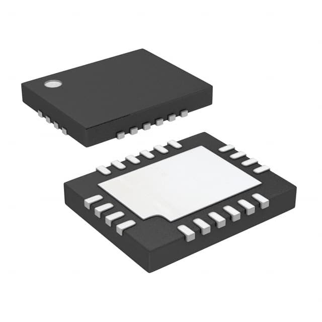
- Part No.:
- LTC4125EUFD
- Manufacturer:
- Analog Devices Inc.
- Category:
- Power Management - Specialized
- Package:
- 20-WFQFN Exposed Pad
- Datasheet:
-
 LTC4125EUFD.pdf
- Description:
- IC POWER MANAGEMENT
- Quantity:
- Payment:

- Shipping:

Inventory:1,642
Please send an inquiry. Send us your inquiry, and we will respond immediately.
Product details
Overview
LTC4125EUFD from Analog Devices is a monolithic full-bridge AutoResonant™ wireless power transmitter IC designed for closed-loop, efficiency-optimized charging of wearable and space-constrained Li-ion batteries. It delivers over 5 W output, implements zero-crossing-based resonant frequency tracking, supports duty cycle control via PTH1/PTH2 pins, and integrates overtemperature and resonant tank overvoltage protection. It pairs with the LTC4124 receiver to enable analog feedback without digital communication.
For engineers reviewing the LTC4125EUFD datasheet, LTC4125EUFD pinout, LTC4125EUFD application, or LTC4125EUFD equivalent, this page provides verified technical context on AutoResonant tank drive, PTHx-controlled duty cycle modulation, FB-based load detection, thermal safety architecture, and half-bridge reconfiguration capability - all critical for low-footprint, high-efficiency wireless charging system design.
Technical Context
The LTC4125EUFD drives a series-resonant LC tank (LTX + CTX) using an internal full-bridge AutoResonant converter that locks switching frequency to the tank's natural resonance via zero-crossing detection on SW1/SW2 outputs. Its internal 5-bit DAC sweeps PTHx voltage to search for valid load presence, stopping upon detecting FB pin voltage patterns indicative of coupled receiver operation.
Each half-bridge driver's duty cycle is directly proportional to its PTHx pin voltage; external PWM-controlled FETs can actively discharge CPTHx to reduce average PTHx voltage and lower transmit power. The device supports half-bridge mode by floating SW2 and grounding PTH2, enabling wider PTH1 control range and reduced gain for fine-grained power regulation.
Key Specifications
| Parameter | Value and Actual Design Meaning |
|---|---|
| Output Power | Over 5 W delivered to properly coupled receiver - enables fast charging of small Li-ion cells in wearables. |
| Topology | Monolithic full-bridge AutoResonant converter - eliminates need for external gate drivers or timing controllers. |
| Resonance Tracking | Zero-crossing detector synchronizes SW1/SW2 switching to LTX–CTX tank resonance - maintains peak efficiency across coil misalignment. |
| Duty Cycle Control | PTH1/PTH2 pins accept 0 V to 1.25 V analog input to set bridge driver duty cycle - enables closed-loop analog feedback without MCU. |
| Load Detection | FB pin monitors tank voltage transients to detect receiver presence and initiate/terminate DAC sweep - avoids false start under no-load conditions. |
| Safety Protection | Integrated overtemperature shutdown and resonant tank overvoltage clamp - prevents thermal runaway and capacitor stress during detuning. |
Pinout & Package
Package: 20-pin 4 mm × 4 mm QFN (EUFD), exposed pad for thermal dissipation, RoHS-compliant.
| Pin/Terminal | Circuit Role | Design Meaning |
|---|---|---|
| VIN | Power supply input | 4.5 V to 5.5 V main supply rail - powers internal logic and half-bridge drivers; requires local 4.7 µF ceramic bypass. |
| SW1, SW2 | Half-bridge output terminals | Drive external series-resonant tank; SW2 can be left open to configure half-bridge mode with SW1–GND connection. |
| PTH1, PTH2 | Duty cycle control inputs | Analog voltage inputs (0–1.25 V) setting respective bridge driver duty cycle; internal pull-up + external FET discharge enables dynamic power adjustment. |
| FB | Feedback detection input | Monitors tank voltage waveform to identify receiver coupling events - triggers internal DAC sweep start/stop and load validation. |
| PTHM | Initial DAC reference input | Sets starting voltage level of internal 5-bit DAC before sweep begins - defines maximum achievable duty cycle and peak transmit power. |
| GND | Ground reference | Signal and power ground; tied to exposed thermal pad - mandatory for thermal performance and noise immunity. |
Key Features
| Feature | Design Value |
|---|---|
| AutoResonant™ frequency tracking | Maintains optimal phase alignment between tank current and voltage across ±3 mm air gap variation - sustains >85% relative efficiency under misalignment. |
| Programmable duty cycle control | PTHx pin voltage directly scales bridge driver on-time - enables analog closed-loop power regulation without added microcontroller or communication interface. |
| Integrated foreign object detection support | Multiple detection methods (frequency shift, Q-factor change, thermal rise) implemented via FB monitoring and internal comparators - reduces BOM count for safety compliance. |
| Configurable half-bridge mode | Disabling SW2 and grounding PTH2 reduces gain and extends PTH1 control range - improves resolution for low-power receivers like LTC4124 (100 mA). |
| Thermal and overvoltage protection | On-die temperature sensor shuts down SWx drivers above 150°C; internal clamp limits tank voltage to safe threshold - prevents damage during coil detuning or no-load condition. |
Applications
| Wearable Fitness Tracker Charging | Medical Patch Device Power Delivery |
|---|---|
|
Use Scenario: Wireless charging of ultra-thin wrist-worn devices with <6 mm board height and <3 mm air gap tolerance. IC Role / Device Role / Timing Role: LTC4125EUFD acts as adaptive power source, dynamically adjusting transmit amplitude based on LTC4124 shunt feedback to maintain constant 100 mA charge current despite coil misalignment. Use Value: Eliminates need for precise mechanical alignment fixtures and enables user-friendly "drop-and-charge" placement while sustaining battery health through regulated power delivery. |
Use Scenario: Recharging disposable or reusable electronic medical patches worn on skin with strict thermal limits (<40°C surface rise). IC Role / Device Role / Timing Role: LTC4125EUFD serves as thermally aware transmitter, reducing output power when LTC4124 enters shunt mode - minimizing heat generation in sensitive biointerface applications. Use Value: Prevents localized heating at skin interface by matching transmit power to real-time receiver demand, meeting ISO 14971 risk management requirements for patient-worn electronics. |
| Implantable Sensor Battery Management | Industrial IoT Node Maintenance-Free Charging |
|
Use Scenario: In-body or subcutaneous sensor modules requiring hermetic, connectorless charging through tissue layers. IC Role / Device Role / Timing Role: LTC4125EUFD functions as resonant power amplifier with adaptive gain control, compensating for variable coupling due to tissue swelling or positional drift. Use Value: Ensures reliable energy transfer across changing biological interfaces without requiring recalibration or firmware updates - critical for long-term implant reliability. |
Use Scenario: Remote industrial sensors mounted inside sealed enclosures where battery replacement is logistically prohibitive. IC Role / Device Role / Timing Role: LTC4125EUFD operates as maintenance-free power source, using FB-based load detection to confirm receiver presence before initiating transmission - preventing idle power waste. Use Value: Extends field deployment life beyond 10 years by eliminating scheduled battery swaps and enabling periodic wireless top-ups during routine maintenance windows. |
Equivalent & Alternatives
The following parts are listed as comparable options for similar wireless power transmitter applications.
| Alternative Part | Technical Difference | Application Difference | Selection Advice |
|---|---|---|---|
| MP-A21 (MPS) | Fixed-frequency 6.78 MHz Class-E transmitter; no AutoResonant frequency tracking or PTHx analog control - relies on external MCU for closed-loop adjustment. | Requires additional microcontroller, ADC, and communication interface to replicate LTC4125EUFD's analog feedback path - increases receiver-side component count and footprint. | Select MP-A21 only if operating at ISM 6.78 MHz band is mandatory and system-level digital control infrastructure already exists. |
| BQ51221 (TI) | Integrated Qi-compliant 5 W transmitter with digital control stack; lacks direct PTHx-style analog duty cycle input - closed loop requires bidirectional communication protocol. | Designed for smartphone accessory ecosystems; incompatible with analog shunt-feedback schemes like LTC4124 - mandates Qi-certified receiver pairing. | Choose BQ51221 only when Qi compliance and interoperability with standard receivers are required, not for custom low-footprint analog-loop systems. |
Compared with MP-A21 and BQ51221, the LTC4125EUFD uniquely enables true analog closed-loop control without MCU involvement or protocol stack overhead - delivering lower BOM cost, smaller receiver footprint, and faster transient response in proprietary wearable and medical charging systems.
Availability
LTC4125EUFD is available at Aetrix Electronics and suitable for wearable fitness trackers, medical patch devices, implantable sensors, and industrial IoT nodes requiring stable component supply, long-lifecycle support, and consistent parametric performance across production batches.
Supply support for LTC4125EUFD includes scheduled delivery planning, volume procurement assistance, BOM continuity management, traceable sourcing, and lifecycle availability coordination for OEM customers, industrial embedded developers, connected-device designers, and electronics production programs.
Manufacturer
Analog Devices, Inc. (ADI) is a global leader in high-performance analog, mixed-signal, and digital signal processing semiconductors, serving precision instrumentation, industrial automation, communications, and healthcare markets.
The LTC4125EUFD belongs to ADI's Power by Linear™ wireless power management product line, engineered specifically for compact, thermally constrained, and safety-critical battery charging applications where analog feedback simplicity and reliability outweigh digital protocol complexity.
FAQ
What is the primary function of the LTC4125EUFD in a wireless charging system?
The LTC4125EUFD serves as a full-bridge AutoResonant™ wireless power transmitter IC that drives a series-resonant LC tank to deliver controlled power to a receiver like the LTC4124. Its core function is to maximize power transfer efficiency by dynamically adjusting duty cycle via PTH1/PTH2 pins, track tank resonance in real time, and provide integrated safety protections - all without requiring a digital controller on the receiver side. The LTC4125EUFD enables analog closed-loop regulation through simple external circuitry.
How does the LTC4125EUFD achieve closed-loop control without digital communication?
The LTC4125EUFD achieves closed-loop control by interpreting analog feedback from the receiver's shunting behavior. When the LTC4124 receiver shunts its tank to regulate VCC, it causes a measurable rise in the LTC4125EUFD's transmit tank voltage. This voltage change is demodulated using a half-wave rectifier, RC filter, and comparator to generate a pulse signal fed into the PTH1 control pin. The LTC4125EUFD then adjusts its duty cycle accordingly - forming a fully analog feedback loop with no data packets or protocols required.
Can the LTC4125EUFD operate in half-bridge mode, and how is it configured?
Yes, the LTC4125EUFD can be configured as a half-bridge transmitter to reduce gain and extend control range for low-power receivers. This is achieved by leaving the SW2 pin unconnected and shorting the PTH2 pin to GND. The transmit resonant tank is then connected between SW1 and GND. This configuration allows finer PTH1 voltage resolution and improved linearity for applications like the 100 mA LTC4124-based charger, and is explicitly supported in the LTC4125EUFD's functional description and application schematics.
What protection features are integrated into the LTC4125EUFD?
The LTC4125EUFD integrates overtemperature shutdown, resonant tank overvoltage clamping, and multiple foreign object detection (FOD) mechanisms - including frequency shift detection, Q-factor monitoring, and thermal rise sensing - all coordinated through the FB pin interface. These protections activate autonomously without external supervision, ensuring safe operation during coil detuning, no-load conditions, or presence of metallic objects near the transmit coil. Each protection mechanism is documented in the LTC4125EUFD datasheet with defined thresholds and response times.
What is the role of the FB pin on the LTC4125EUFD?
The FB pin on the LTC4125EUFD monitors voltage transients across the resonant tank to detect coupling status and receiver load activity. During startup, it triggers the internal 5-bit DAC sweep to find a valid load; once coupled, specific FB voltage patterns indicate successful energy transfer and cause the sweep to pause. During operation, FB continues to validate load presence and supports foreign object detection. Its behavior is fundamental to the LTC4125EUFD's autonomous load identification and safety architecture - not merely a passive monitoring node.
LTC4125EUFD Specifications
- Product attributes
- Attribute value
- Manufacturer:
- Analog Devices Inc.
- Series:
- -
- Package/Case:
- 20-WFQFN Exposed Pad
- Packaging:
- Tube
- Product Status:
- Obsolete
- Applications:
- Wireless Power Transmitter
- Current - Supply:
- 1mA
- Voltage - Supply:
- 3V ~ 5.5V
- Operating Temperature:
- -40°C ~ 125°C
- Grade:
- -
- Qualification:
- -
- Mounting Type:
- Surface Mount
- Supplier Device Package:
- 20-QFN (4x5)
LTC4125EUFD FAQ
1.How can I place an order for LTC4125EUFD through Aetrix?
Please submit a Request for Quotation (RFQ) for LTC4125EUFD on Aetrix. Our sales agent will provide a competitive quotation and guide you through the order confirmation once you accept the terms.
2.Are the price and stock information for LTC4125EUFD reliable?
The price and inventory of LTC4125EUFD are updated periodically and may fluctuate due to market conditions. Stock and pricing data are typically refreshed every 24 hours. Quotation validity for LTC4125EUFD is usually 5 days.
3.What payment methods are accepted for LTC4125EUFD?
We accept Wire Transfer, PayPal, Credit Card, Western Union, MoneyGram, and Escrow for LTC4125EUFD transactions.
Note: Certain payment methods may incur a processing fee.
4.How is shipping managed for LTC4125EUFD?
LTC4125EUFD orders can be shipped via leading logistics carriers, including DHL, UPS, FedEx, TNT, or Registered Mail.
Once your LTC4125EUFD order is processed, you will receive an email with the shipment details and tracking number.
Note: Tracking information may take up to 24 hours to appear. Express delivery typically takes 3–5 business days.
5.How can I obtain technical support or documentation for LTC4125EUFD?
For technical support, including LTC4125EUFD datasheets, pinout diagrams, or application guidance, please contact our engineering support team. They can provide detailed documentation and assistance for your LTC4125EUFD requirements.
6.How does Aetrix verify that LTC4125EUFD is sourced from the original manufacturer or authorized distributors?
All LTC4125EUFD products on Aetrix are procured from qualified distributors and authorized channels. Our dedicated quality assurance team conducts strict verification, including traceability checks and, if necessary, third-party testing. This ensures that LTC4125EUFD meets industry standards.
7.What is the process for return or replacement of LTC4125EUFD?
All LTC4125EUFD units undergo pre-shipment inspection (PSI). If there is an issue with LTC4125EUFD, returns or replacements are accepted under the following conditions:
1.Quantity discrepancies, incorrect items, or visible external defects (such as breakage or corrosion), acknowledged by Aetrix.
2.The issue is reported within 90 days of delivery.
3.The LTC4125EUFD part is unused and in its original packaging.
Return procedure for LTC4125EUFD:
1.Submit a request within 90 days.
2.Obtain a Return Material Authorization (RMA) from Aetrix.
LTC4125EUFD Tags

-
TPS2511DGNR
Texas Instruments

-
UTC2000/MG
Microchip Technology

-
TUSB320HAIRWBR
Texas Instruments

-
TPS61252DSGR
Texas Instruments

-
PI5USB30216CXUAEX
Diodes Incorporated

-
SN6501DBVR
Texas Instruments

-
CYPD3177-24LQXQT
Infineon Technologies
-
SN6501QDBVRQ1
Texas Instruments

-
STUSB1600AQTR
STMicroelectronics

-
SN6505BDBVR
Texas Instruments
-
SN6501DBVT
Texas Instruments

-
TPS65150PWPR
Texas Instruments
Tech Hub

A practical engineering guide to 3.3V and 5V logic compatibility, input thresholds, resistor dividers, translator ICs, MOSFET level shifting, I2C pull-ups, timing limits and power-sequencing risks.

The 74HC595 uses push-pull logic outputs, while the TPIC6B595 uses 50 V open-drain DMOS sinks for higher-power loads. This guide compares timing, current limits, 3.3 V interfacing, load wiring, thermal…

The 74HC595 converts serial data into eight stable parallel outputs. This guide covers pin functions, shift and storage timing, OE and MR behavior, drive-current limits, cascading, voltage compatibilit…

A technical comparison of level-sensitive latches and edge-triggered flip-flops, covering timing windows, setup and hold limits, master–slave operation, time borrowing, race-through, HDL inference and…

A D latch stores one bit while Enable controls when data can pass. This reference covers gate-level operation, truth tables, transparency, setup and hold timing, LE versus OE, common ICs and practical …

An SR latch stores one bit through cross-coupled feedback. This engineering reference covers NOR and NAND implementations, truth tables, forbidden-state recovery, gated operation, switch debouncing, fa…

Latch circuits retain one bit through feedback. This technical reference covers SR and D latches, truth tables, transparency, timing limits, latch-versus-flip-flop behavior, applications and common log…

An engineering guide to LED driver operation, constant-current and constant-voltage outputs, linear and switching topologies, dimming, IC selection, calculations, replacement compatibility, and fault c…

Operational amplifier guide covering op amp basics, feedback, ideal vs real op amps, common configurations, buffer circuits, offset, bias current, gain-bandwidth, slew rate, rail-to-rail limits and sel…

Jumper cables guide covering safe connection order, red and black clamp placement, final ground connection, cable gauge, length, clamp quality, copper vs CCA cables, jump starter comparison and battery…


