
 My Inquiry
 My Account


Analog Devices Inc. LTC4125EUFD#PBF
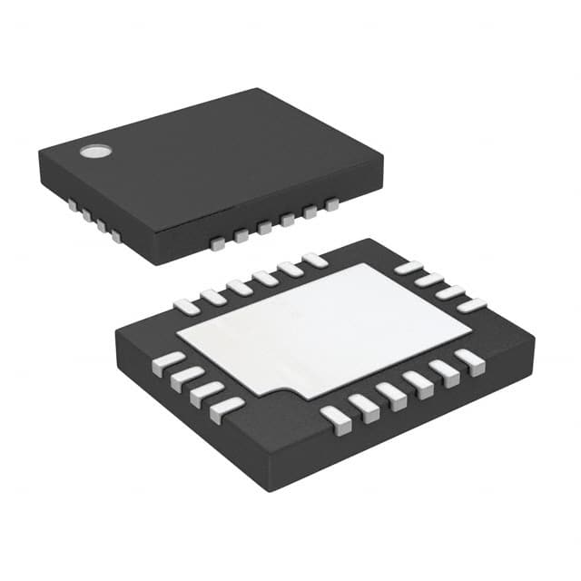
- Part No.:
- LTC4125EUFD#PBF
- Manufacturer:
- Analog Devices Inc.
- Category:
- Power Management - Specialized
- Package:
- 20-WFQFN Exposed Pad
- Datasheet:
-
 LTC4125EUFD#PBF.pdf
- Description:
- 5W AUTORESONANT WIRELESS POWER T
- Quantity:
- Payment:

- Shipping:

Inventory:618
Please send an inquiry. Send us your inquiry, and we will respond immediately.
Product details
Overview
LTC4125EUFD#PBF from Analog Devices (formerly Linear Technology) is a monolithic 5W AutoResonant wireless power transmitter IC that drives a full-bridge LC tank to deliver regulated power across an air gap. It features integrated 100mΩ MOSFETs, programmable input current limiting (0.785–0.815V threshold), NTC-based temperature monitoring, and multi-method foreign object detection. It operates in industrial handhelds and medical equipment requiring contactless charging with fault-safe operation.
For engineers reviewing the LTC4125EUFD#PBF datasheet, LTC4125EUFD#PBF pinout, LTC4125EUFD#PBF application, or LTC4125EUFD#PBF equivalent, key selection considerations include its 50kHz–250kHz AutoResonant frequency tracking, 3V–5.5V input range, 20-pin 4mm × 5mm QFN package, dual-input current sense interface (IS+/IS−), and FB-based load detection for adaptive power delivery.
Technical Context
The LTC4125EUFD#PBF implements a patent-pending AutoResonant control architecture that continuously adjusts switching frequency to match the series LC tank's resonant frequency-enabling maximum power transfer despite coil inductance drift or temperature variation. Its internal full-bridge driver uses pulse-width modulation synchronized to tank zero-crossing to maintain phase alignment between SW1/SW2 voltage and coil current.
Power optimization is achieved via periodic transmit power search: the device performs linear pulse-width ramping while monitoring FB voltage and IMON current, halting at the first valid exit condition-either sufficient receiver load detection (ΔVFB step), input current threshold crossing (0.800V), or fault activation (FTH/NTC/DTH). Fault responses include immediate power shutdown and STAT pin high-impedance assertion.
Key Specifications
| Parameter | Value and Actual Design Meaning |
|---|---|
| Input Voltage Range | 3V to 5.5V - powers internal logic and full-bridge drivers; requires separate bypass capacitors on IN, IN1, IN2 pins. |
| Output Power Capability | Over 5W - delivered wirelessly to tuned receiver via series LC tank driven by integrated 100mΩ MOSFETs. |
| AutoResonant Frequency Range | 50kHz to 250kHz - dynamically tracks LC tank resonance without external PLL or crystal; eliminates manual tuning. |
| Input Current Threshold | 0.785V to 0.815V at IMON - sets average input current limit during power search; programmable via RIN/RIMON/RIS. |
| Operating Junction Temp | –40°C to 125°C - specified for E-grade; thermal protection disables output if die temperature exceeds 125°C. |
| Package | 20-lead 4mm × 5mm QFN (UFD) - thermally enhanced with exposed pad tied to GND; θJA = 43°C/W. |
| Foreign Object Detection | Multi-method: FTH-based frequency shift (>250kHz), NTC-based overtemperature, DTH-based ΔVFB step size, and ILIM-based current overload. |
Pinout & Package
Package: 20-lead plastic QFN (UFD20), 4mm × 5mm, 0.75mm profile, exposed thermal pad (Pin 21) must be connected to GND.
| Pin/Terminal | Circuit Role | Design Meaning |
|---|---|---|
| IN (1), IN1 (20), IN2 (17) | Independent supply inputs | Power three internal domains: logic (IN), upper half-bridge (IN1), lower half-bridge (IN2); each requires local bypass capacitance (1µF, 47µF, 47µF). |
| SW1 (19), SW2 (18) | Full-bridge switch nodes | Center taps of internal H-bridge; connect series LC tank between SW1–SW2 for full-bridge operation (higher power) or SW1–GND for half-bridge. |
| FB (13) | Resonance feedback input | Monitors rectified peak tank voltage via resistor divider; used to detect receiver load presence and terminate power search on large ΔVFB. |
| IS+ (4), IS– (3) | Differential current sense inputs | Kelvin-connected to sense resistor (RIS) upstream of IN; enable programmable average input current limit and monitor via IMON pin. |
| IMON (5) | Current monitor output | Sources current proportional to IIN; voltage across RIMON sets thresholds VITH (0.800V) and VILIM (1.200V) for search pause and fault shutdown. |
| NTC (6) | Thermistor interface | Voltage divider with IN determines temperature; stops power if VNTC falls below 33%–37% of VIN (hot condition or metal object detection). |
| FTH (9), DTH (7) | Frequency/ΔVFB threshold inputs | Resistor dividers set max allowable resonant frequency (FTH) and minimum detectable ΔVFB step (DTH) for foreign object detection. |
| STAT (8) | Open-drain status indicator | Pulled low during active power delivery; high-impedance during fault or no-receiver condition - enables LED or microcontroller monitoring. |
Key Features
| Feature | Design Value |
|---|---|
| AutoResonant frequency tracking | Maintains exact LC tank resonance without external timing components; adapts to inductance/capacitance drift over temperature and coupling variation. |
| Optimum Power Search algorithm | Performs periodic linear pulse-width ramping to find minimal transmit power satisfying receiver load - improves system efficiency and reduces EMI/heat. |
| Multi-signal foreign object detection | Simultaneously monitors frequency shift (FTH), ΔVFB step size (DTH), input current limit (ILIM), and NTC voltage to halt power on conductive intrusion or thermal fault. |
| Programmable input current limit | Configurable average current threshold (0.785–0.815V at IMON) and hard limit (1.175–1.225V) using external resistors - protects source and enables compliance with USB PD or battery charge profiles. |
| Thermally enhanced QFN package | 4mm × 5mm footprint with exposed pad ensures 43°C/W thermal resistance - sustains 5W operation in compact industrial or medical enclosures without forced airflow. |
Applications
| Medical Wearables | Industrial Handheld Scanners |
|---|---|
Use Scenario: Charging implantable or skin-contact diagnostic sensors without connectors or battery replacement. IC Role / Device Role / Timing Role: Wireless power transmitter controlling resonant energy transfer across 3–10mm air gap to sealed receiver coil. Use Value: Eliminates mechanical wear and moisture ingress; NTC and FTH detection prevents tissue heating from metallic implants or misaligned coils. | Use Scenario: Recharging rugged barcode scanners used in warehouses with frequent drop events and dust exposure. IC Role / Device Role / Timing Role: Primary-side controller managing full-bridge drive, power search, and fault response in portable charging cradles. Use Value: Enables maintenance-free operation; AutoResonant adaptation compensates for coil deformation after impact; CTD/CTS timing ensures reliable search under variable load conditions. |
| Military Field Sensors | Smart Home Health Monitors |
Use Scenario: Powering unattended environmental sensors deployed in remote or hazardous locations with no access to wired infrastructure. IC Role / Device Role / Timing Role: Autonomous wireless power source initiating periodic power search only when receiver is present - minimizing standby power draw. Use Value: Extends battery life of paired receivers; multi-threshold fault detection (NTC, FTH, ILIM) ensures safe operation near explosive atmospheres or metallic structures. | Use Scenario: Contactless charging of blood pressure cuffs or glucose meters placed on bedside docks overnight. IC Role / Device Role / Timing Role: Integrated transmitter IC delivering up to 5W with precise load matching via FB feedback and IMON current monitoring. Use Value: Reduces user error (no plug insertion); programmable PTHM/PTH1/PTH2 allows tuning of minimum pulse width for fast startup with low-power receivers. |
Equivalent & Alternatives
The following parts are listed as comparable options for similar wireless power transmitter applications.
| Alternative Part | Technical Difference | Application Difference | Selection Advice |
|---|---|---|---|
| BQ51221RGER | TI part uses proprietary Qi-compliant digital control; requires external MCU for configuration; 3.3V–5.5V input; 3.5W typical output. | Designed for Qi-certified consumer electronics; lacks NTC input and analog FB-based load detection. | Choose BQ51221RGER only if Qi compliance and host MCU coordination are required; LTC4125EUFD#PBF offers simpler analog autonomy and higher 5W capability. |
| MP-A21 | STMicroelectronics reference design module; integrates MCU, gate drivers, and coil; 5V input; ~4W output; pre-certified for WPC 1.2. | Complete subsystem vs. single IC; includes firmware, thermal management, and communication stack. | Choose MP-A21 for rapid prototyping of certified transmitters; LTC4125EUFD#PBF provides greater design flexibility for custom coil geometry, frequency tuning, and safety logic. |
Compared with BQ51221RGER and MP-A21, the LTC4125EUFD#PBF delivers higher autonomous power (5W vs. ≤4W), eliminates need for external MCU or certification overhead, and provides direct analog interfaces (FB, NTC, FTH) for deterministic, real-time fault response in safety-critical embedded systems.
Availability
LTC4125EUFD#PBF is available at Aetrix Electronics and suitable for medical equipment, industrial handhelds, and military field sensors requiring stable component supply, long-term lifecycle support, and guaranteed RoHS-compliant lead-free packaging.
Supply support for LTC4125EUFD#PBF includes scheduled delivery planning, volume procurement assistance, BOM continuity management, traceable sourcing, and lifecycle availability coordination for OEM customers, industrial embedded developers, connected-device designers, and electronics production programs.
Manufacturer
Analog Devices acquired Linear Technology in 2017 and maintains its precision analog and power management product lines with full datasheet, simulation model, and application note support.
The LTC4125EUFD#PBF belongs to Linear's wireless power controller family, designed specifically for high-efficiency, fault-resilient, and self-tuning resonant power transmission in space-constrained, safety-regulated environments.
FAQ
What is the primary function of the LTC4125EUFD#PBF in a wireless power system?
The LTC4125EUFD#PBF serves as a fully autonomous wireless power transmitter controller. It drives a series LC tank via an integrated full-bridge to deliver over 5W across an air gap. Its core functions include AutoResonant frequency tracking, Optimum Power Search for load-matched transmission, and multi-method foreign object detection - all implemented without external microcontroller intervention. The LTC4125EUFD#PBF replaces discrete gate drivers, controllers, and protection circuitry with a single IC optimized for reliability in medical and industrial settings.
How does the LTC4125EUFD#PBF detect foreign objects during wireless power transfer?
The LTC4125EUFD#PBF employs four independent foreign object detection mechanisms: (1) FTH pin monitors resonant frequency shift - a conductive object lowers tank inductance, raising frequency above the programmed threshold; (2) DTH pin detects abnormally small ΔVFB steps during power search, indicating weak coupling or lossy material; (3) NTC pin senses temperature rise via thermistor voltage drop; and (4) ILIM comparator triggers immediate shutdown if input current exceeds 1.200V at IMON. All four methods operate concurrently and cause power cessation within microseconds. The LTC4125EUFD#PBF does not rely on communication protocols but uses direct analog sensing for deterministic response.
Can the LTC4125EUFD#PBF operate with different LC tank configurations?
Yes, the LTC4125EUFD#PBF supports both full-bridge and half-bridge LC tank topologies. For full-bridge operation - delivering maximum power - connect the series LC network between SW1 and SW2. For half-bridge operation - useful in space-constrained designs - connect the LC network between SW1 and GND. The AutoResonant engine automatically adapts to the tank's natural frequency regardless of L (e.g., 24µH) or C (e.g., 100nF) values, and the CTS/CTD pins allow tuning of search settling time (1ms–20ms) and inter-search delay (≥1s). The LTC4125EUFD#PBF's 50kHz–250kHz operating range accommodates a wide variety of coil geometries and coupling coefficients.
What is the role of the FB pin in the LTC4125EUFD#PBF, and how is it configured?
The FB (Feedback) pin on the LTC4125EUFD#PBF monitors the rectified peak voltage across the transmit LC tank via a resistor divider (e.g., RFB1/RFB2). During the Optimum Power Search, the LTC4125EUFD#PBF increments pulse width and measures resulting ΔVFB; a large step indicates the receiver load has been satisfied. If FB voltage exceeds VIN (over-range threshold), the device halts transmission - protecting against open-circuit or mismatched receiver conditions. The FB pin leakage is ≤1.2µA, and its over-range hysteresis is 40mV. Leaving FB unconnected or shorting it to GND disables auto-load detection, forcing fixed-power operation. The LTC4125EUFD#PBF requires no external compensation on this pin.
Does the LTC4125EUFD#PBF require external components for basic operation, and what are the critical ones?
Yes, the LTC4125EUFD#PBF requires several external components for safe and functional operation: (1) Three bypass capacitors - 1µF on IN, 47µF on IN1, 47µF on IN2; (2) Series LC tank connected between SW1 and SW2 (or SW1–GND); (3) Resistor divider from tank rectified peak to FB; (4) Sense resistor (RIS) between input supply and IS–, with RIN and RIMON setting current thresholds; (5) NTC thermistor from NTC to GND and pull-up resistor from IN to NTC; (6) Capacitors on CTS (1–20ms settling) and CTD (≥1s delay) pins. The LTC4125EUFD#PBF integrates all power switches, drivers, comparators, and oscillators - eliminating need for gate drivers, op-amps, or microcontrollers.
LTC4125EUFD#PBF Specifications
- Product attributes
- Attribute value
- Manufacturer:
- Analog Devices Inc.
- Series:
- -
- Package/Case:
- 20-WFQFN Exposed Pad
- Packaging:
- Tube
- Product Status:
- Active
- Applications:
- Wireless Power Transmitter
- Current - Supply:
- 1mA
- Voltage - Supply:
- 3V ~ 5.5V
- Operating Temperature:
- -40°C ~ 125°C
- Grade:
- -
- Qualification:
- -
- Mounting Type:
- Surface Mount
- Supplier Device Package:
- 20-QFN (4x5)
LTC4125EUFD#PBF FAQ
1.How can I place an order for LTC4125EUFD#PBF through Aetrix?
Please submit a Request for Quotation (RFQ) for LTC4125EUFD#PBF on Aetrix. Our sales agent will provide a competitive quotation and guide you through the order confirmation once you accept the terms.
2.Are the price and stock information for LTC4125EUFD#PBF reliable?
The price and inventory of LTC4125EUFD#PBF are updated periodically and may fluctuate due to market conditions. Stock and pricing data are typically refreshed every 24 hours. Quotation validity for LTC4125EUFD#PBF is usually 5 days.
3.What payment methods are accepted for LTC4125EUFD#PBF?
We accept Wire Transfer, PayPal, Credit Card, Western Union, MoneyGram, and Escrow for LTC4125EUFD#PBF transactions.
Note: Certain payment methods may incur a processing fee.
4.How is shipping managed for LTC4125EUFD#PBF?
LTC4125EUFD#PBF orders can be shipped via leading logistics carriers, including DHL, UPS, FedEx, TNT, or Registered Mail.
Once your LTC4125EUFD#PBF order is processed, you will receive an email with the shipment details and tracking number.
Note: Tracking information may take up to 24 hours to appear. Express delivery typically takes 3–5 business days.
5.How can I obtain technical support or documentation for LTC4125EUFD#PBF?
For technical support, including LTC4125EUFD#PBF datasheets, pinout diagrams, or application guidance, please contact our engineering support team. They can provide detailed documentation and assistance for your LTC4125EUFD#PBF requirements.
6.How does Aetrix verify that LTC4125EUFD#PBF is sourced from the original manufacturer or authorized distributors?
All LTC4125EUFD#PBF products on Aetrix are procured from qualified distributors and authorized channels. Our dedicated quality assurance team conducts strict verification, including traceability checks and, if necessary, third-party testing. This ensures that LTC4125EUFD#PBF meets industry standards.
7.What is the process for return or replacement of LTC4125EUFD#PBF?
All LTC4125EUFD#PBF units undergo pre-shipment inspection (PSI). If there is an issue with LTC4125EUFD#PBF, returns or replacements are accepted under the following conditions:
1.Quantity discrepancies, incorrect items, or visible external defects (such as breakage or corrosion), acknowledged by Aetrix.
2.The issue is reported within 90 days of delivery.
3.The LTC4125EUFD#PBF part is unused and in its original packaging.
Return procedure for LTC4125EUFD#PBF:
1.Submit a request within 90 days.
2.Obtain a Return Material Authorization (RMA) from Aetrix.
LTC4125EUFD#PBF Tags

-
TPS2511DGNR
Texas Instruments

-
UTC2000/MG
Microchip Technology

-
TUSB320HAIRWBR
Texas Instruments

-
TPS61252DSGR
Texas Instruments

-
PI5USB30216CXUAEX
Diodes Incorporated

-
SN6501DBVR
Texas Instruments

-
CYPD3177-24LQXQT
Infineon Technologies
-
SN6501QDBVRQ1
Texas Instruments

-
STUSB1600AQTR
STMicroelectronics

-
SN6505BDBVR
Texas Instruments
-
SN6501DBVT
Texas Instruments

-
TPS65150PWPR
Texas Instruments
Tech Hub

A practical engineering guide to 3.3V and 5V logic compatibility, input thresholds, resistor dividers, translator ICs, MOSFET level shifting, I2C pull-ups, timing limits and power-sequencing risks.

The 74HC595 uses push-pull logic outputs, while the TPIC6B595 uses 50 V open-drain DMOS sinks for higher-power loads. This guide compares timing, current limits, 3.3 V interfacing, load wiring, thermal…

The 74HC595 converts serial data into eight stable parallel outputs. This guide covers pin functions, shift and storage timing, OE and MR behavior, drive-current limits, cascading, voltage compatibilit…

A technical comparison of level-sensitive latches and edge-triggered flip-flops, covering timing windows, setup and hold limits, master–slave operation, time borrowing, race-through, HDL inference and…

A D latch stores one bit while Enable controls when data can pass. This reference covers gate-level operation, truth tables, transparency, setup and hold timing, LE versus OE, common ICs and practical …

An SR latch stores one bit through cross-coupled feedback. This engineering reference covers NOR and NAND implementations, truth tables, forbidden-state recovery, gated operation, switch debouncing, fa…

Latch circuits retain one bit through feedback. This technical reference covers SR and D latches, truth tables, transparency, timing limits, latch-versus-flip-flop behavior, applications and common log…

An engineering guide to LED driver operation, constant-current and constant-voltage outputs, linear and switching topologies, dimming, IC selection, calculations, replacement compatibility, and fault c…

Operational amplifier guide covering op amp basics, feedback, ideal vs real op amps, common configurations, buffer circuits, offset, bias current, gain-bandwidth, slew rate, rail-to-rail limits and sel…

Jumper cables guide covering safe connection order, red and black clamp placement, final ground connection, cable gauge, length, clamp quality, copper vs CCA cables, jump starter comparison and battery…


