
 My Inquiry
 My Account


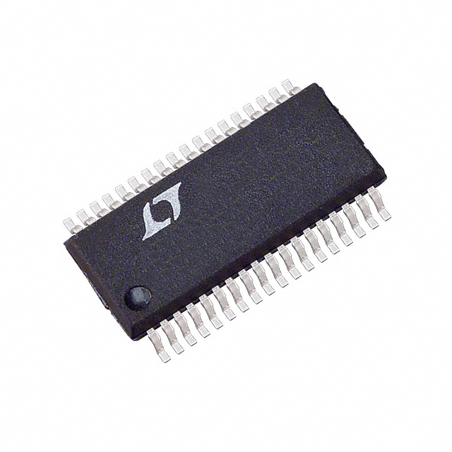
Analog Devices Inc. LTC4259ACGW-1#PBF
- Part No.:
- LTC4259ACGW-1#PBF
- Manufacturer:
- Analog Devices Inc.
- Category:
- Power Over Ethernet (PoE) Controllers
- Package:
- 36-BSOP (0.295", 7.50mm Width)
- Datasheet:
-
 LTC4259ACGW-1#PBF.pdf
- Description:
- IC POE CNTRL 4 CHANNEL 36SSOP
- Quantity:
- Payment:

- Shipping:

Inventory:2,066
Please send an inquiry. Send us your inquiry, and we will respond immediately.
Product details
Overview
LTC4259ACGW-1#PBF from Analog Devices (formerly Linear Technology) is a quad –48V IEEE 802.3af-compliant Power Sourcing Equipment (PSE) controller for Ethernet-powered infrastructure. It integrates four independent hot-swap ports with PD detection, classification, current-limited gate drive, short-circuit protection, and AC/DC disconnect-each supporting up to Class 4 (35.4W) power delivery. It operates in autonomous or I²C-controlled mode and targets IP phone systems and DTE power distribution.
For engineers reviewing the LTC4259ACGW-1#PBF datasheet, LTC4259ACGW-1#PBF pinout, LTC4259ACGW-1#PBF application, or LTC4259ACGW-1#PBF equivalent, key selection considerations include its 36-pin SSOP package, –48V VEE operating range, 4-bit I²C addressability (up to 64 ports), integrated UVLO thresholds (–31V turn-on / –28V turn-off), and AC disconnect capability via OSCIN-driven impedance sensing.
Technical Context
The LTC4259ACGW-1#PBF implements per-port analog front-end circuitry for IEEE 802.3af-compliant detection (235–300 µA first-point current, 15.2–33 kΩ signature resistance window) and classification (Class 0–4 thresholds from 5.5 mA to 48 mA). Its gate drivers support external N-channel MOSFETs with programmable foldback current limiting (VLIM = 201–224 mV), fast pull-down (50 mA), and VEE-referenced output swing (10–15 V above VEE).
It features dual-mode operation: autonomous startup via AUTO pin configuration or host-controlled I²C interface (400 kHz, SMBus-compatible) with interrupt signaling (INT pin), 4-bit address decoding (AD0–AD3), and register-mapped timing control (tDETDLY = 170–590 ms, tDIS = 75–800 ms). AC disconnect uses OSCIN input (100 Hz sine, 2 VPP) amplified to DETECT pins with ±600 µA output drive and ±2.7–3.3 V/V gain.
Key Specifications
| Parameter | Value and Actual Design Meaning |
|---|---|
| VDD Supply Voltage | 3.0–4.0 V - powers digital logic and I²C interface; requires 0.1 µF local bypass to DGND |
| VEE Supply Range | –48 V to –57 V - supports IEEE 802.3af midspan/port voltage compliance with diode/MOSFET drop margin |
| Detection Current (First Point) | 235–300 µA at VDETECT = –10 V - ensures reliable PD signature identification per Clause 33.3.1 |
| Classification Threshold (Class 4) | 31–35 mA - enables full 35.4W power delivery per port under IEEE 802.3af Table 33–7 |
| Current Limit Sense Voltage (VLIM) | 201–224 mV - sets nominal current limit (e.g., 402–448 mA with 0.5 Ω sense resistor) |
| I²C Clock Frequency | Up to 400 kHz - supports standard-mode SMBus communication without timing violation |
| Operating Temperature (C Grade) | 0°C to +70°C - qualified for commercial-grade Ethernet switch and PoE injector applications |
Pinout & Package
Package: 36-pin plastic SSOP (GW), 0.025" pitch, JEDEC MO-153 compliant, RoHS-compliant #PBF finish.
| Pin/Terminal | Circuit Role | Design Meaning |
|---|---|---|
| RESET (1) | Chip reset input | Active-low asynchronous reset; holds all ports off and registers in power-up state until pulled high |
| BYP (2) | Internal –20 V supply output | Drives external 0.1 µF/100 V X7R capacitor; must not connect to other circuitry |
| INT (3) | Open-drain interrupt output | Asserts low on fault events (tSTART/tICUT timeout, disconnect, classification complete); requires external pull-up |
| SCL (4) | I²C clock input | High-impedance SCL line connection; supports 400 kHz bus timing with ≤300 ns fall time |
| SDAOUT (5) | I²C data output | Open-drain output for bidirectional SDA; used with SDAIN to simplify opto-isolation |
| SDAIN (6) | I²C data input | High-impedance input; tied to SDAOUT for standard I²C bus implementation |
| AD3–AD0 (7–10) | I²C address bits | Set 4-bit slave address (010A3A2A1A0)b; enable up to 16 devices × 4 ports = 64 total PSE ports |
| DETECT1–4 (11–14) | PD detection/classification sense | Monitor port signature via RC network; support AC disconnect when driven by OSCIN-amplified signal |
| DGND (15) | Digital ground reference | Return for VDD (3.3 V); must be tied to AGND to avoid ground offset errors |
| VDD (16) | Digital supply input | 3.3 V ±10% logic supply; bypassed locally to DGND with ≥0.1 µF ceramic capacitor |
| SHDN1–4 (17–20) | Port shutdown inputs | Active-low hardware override; forces immediate port disable regardless of register state |
| AGND (21) | Analog ground reference | Return for VEE (–48 V); tied to DGND to maintain common-mode integrity across sense paths |
| SENSE1–4 (22,25,29,32) | Current sense inputs | Monitor external MOSFET source-to-VEE voltage; trigger VLIM/VCUT thresholds for foldback and fault response |
| GATE1–4 (23,26,30,33) | MOSFET gate drivers | VEE-referenced outputs (clamp-limited to +13 V above VEE); provide 50 µA pull-up and 50 mA pull-down |
| OUT1–4 (24,27,31,34) | Output voltage monitors | Connect via 10 kΩ series resistor; indicate "Power Good" when VOUT–VEE drops below 2 V (typ) |
| AUTO (35) | Autonomous mode select | Configures default port behavior (Auto/Semiauto/Manual/Shutdown) at power-up or RESET release |
| OSCIN (36) | AC disconnect oscillator input | Accepts 100 Hz sine wave (2 VPP, –0.3 V to +2.5 V); drives internal amplifier for AC impedance measurement |
Key Features
| Feature | Design Value |
|---|---|
| Quad IEEE 802.3af PSE compliance | Meets full Clause 33 requirements per port-including detection, classification, current limiting, and disconnect-without external firmware |
| Programmable AC disconnect | Uses OSCIN-driven signal to measure PD AC impedance; eliminates false disconnects caused by DC leakage or capacitive loads |
| Per-port current foldback | Reduces current limit threshold when port voltage falls within 18 V of AGND, protecting MOSFETs during brownout or overload |
| Hardware shutdown pins (SHDN1–4) | Enable deterministic, glitch-immune port disable independent of I²C bus activity or register state |
| Integrated UVLO with hysteresis | VEE UVLO turns on at –31 V and off at –28 V (3 V hysteresis), preventing oscillation near minimum PoE voltage |
| Interrupt-driven fault reporting | INT pin signals 8 distinct events (e.g., tICUT timeout, disconnect, classification complete); reduces host polling overhead |
Applications
| IP Phone Power Distribution | VoIP Gateway Midspan Injector |
|---|---|
Use Scenario: Powering IEEE 802.3af-compliant VoIP phones from a centralized switch or standalone injector. IC Role / Device Role / Timing Role: Quad PSE controller managing four independent PoE ports with detection, classification, and controlled power ramp-up. Use Value: Enables simultaneous powering of four phones with guaranteed Class 4 (35.4W) support, AC disconnect to prevent false removal detection, and autonomous operation without host microcontroller. | Use Scenario: Adding PoE capability to legacy non-PoE Ethernet switches via midspan injection. IC Role / Device Role / Timing Role: Hot-swap controller implementing IEEE 802.3af-compliant power sourcing on each of four Ethernet pairs. Use Value: Delivers stable –48 V output with foldback current limiting and short-circuit protection, while supporting I²C coordination across multiple LTC4259A-1 units for scalable multi-port designs. |
| Enterprise Wireless Access Point Hub | Industrial Ethernet Switch Module |
Use Scenario: Centralized powering of ceiling-mounted Wi-Fi access points in office or retail environments. IC Role / Device Role / Timing Role: Four-port PSE managing power sequencing, fault isolation, and thermal management for concurrent AP loads. Use Value: Provides per-port current monitoring (via SENSE pins), programmable disconnect delays (tDIS = 75–800 ms), and interrupt-based event logging for remote diagnostics. | Use Scenario: Embedded PoE in DIN-rail industrial switches requiring extended temperature operation and EMI resilience. IC Role / Device Role / Timing Role: Robust PSE controller with –40°C to +85°C grade variants (LTC4259AI-1), high VEE tolerance (–70 V abs max), and ESD-hardened DETECT pins (±80 mA transient rating). Use Value: Ensures reliable PD detection in noisy factory environments using AC disconnect to reject false triggers from motor noise or cable capacitance. |
Equivalent & Alternatives
The following parts are listed as comparable options for similar quad PoE PSE controller applications.
| Alternative Part | Technical Difference | Application Difference | Selection Advice |
|---|---|---|---|
| MAX5980A | Quad PSE with integrated 100BASE-TX PHY interface; supports IEEE 802.3at (PoE+) up to 30W per port; no AC disconnect feature | Designed for PHY-integrated midspan solutions; lacks OSCIN-driven AC impedance sensing | Select MAX5980A when integrating PHY and PSE on same die; choose LTC4259ACGW-1#PBF when AC disconnect reliability and discrete MOSFET flexibility are required |
| TPS23861 | Quad PSE with integrated DC-DC controller; supports 802.3bt Type 3 (60W) and auto-classification; higher integration but fixed 28-pin TSSOP | Targets higher-power PoE++ systems; includes built-in DC-DC for auxiliary power generation | Select TPS23861 for 60W+ applications with integrated DC-DC; retain LTC4259ACGW-1#PBF for cost-sensitive 802.3af-only deployments with field-proven AC disconnect |
Compared with MAX5980A and TPS23861, the LTC4259ACGW-1#PBF offers superior AC disconnect fidelity for legacy PDs and greater external MOSFET scalability, while trading off higher integration and newer PoE standards support.
Availability
LTC4259ACGW-1#PBF is available at Aetrix Electronics and suitable for IP phone systems, VoIP gateway midspan injectors, enterprise wireless access point hubs, and industrial Ethernet switch modules requiring stable component supply and long-term PoE infrastructure support.
Supply support for LTC4259ACGW-1#PBF includes scheduled delivery planning, volume procurement assistance, BOM continuity management, traceable sourcing, and lifecycle availability coordination for OEM customers, industrial embedded developers, connected-device designers, and electronics production programs.
Manufacturer
Analog Devices acquired Linear Technology in 2017 and maintains full product support, documentation, and qualification for legacy Linear ICs including the LTC4259A family.
The LTC4259A product line was designed specifically for IEEE 802.3af-compliant Power Sourcing Equipment, emphasizing robustness in telecom-grade –48 V environments, autonomous operation, and flexible external FET control for thermal and power optimization.
FAQ
What is the maximum number of LTC4259ACGW-1#PBF devices that can share one I²C bus?
Up to 16 LTC4259ACGW-1#PBF devices can coexist on a single I²C bus using their 4-bit programmable address (AD3–AD0), enabling control of up to 64 independent PoE ports with only two digital lines (SCL and SDA). Each device responds to a unique 7-bit slave address formed as 010A3A2A1A0, ensuring collision-free arbitration.
Does the LTC4259ACGW-1#PBF support IEEE 802.3at (PoE+) or 802.3bt (PoE++) standards?
No, the LTC4259ACGW-1#PBF is strictly IEEE 802.3af-compliant and supports Classes 0–4 (up to 35.4W per port). It does not implement 802.3at's two-event classification or 802.3bt's four-pair power negotiation. For PoE+ or PoE++, consider Analog Devices' LTC4271/LTC4272 or TI's TPS23861 - but note these lack the LTC4259ACGW-1#PBF's dedicated AC disconnect architecture.
How does the AC disconnect function work on the LTC4259ACGW-1#PBF?
The LTC4259ACGW-1#PBF applies a 100 Hz sine wave (via OSCIN pin) to the DETECTn pins through internal amplifiers (±2.7–3.3 V/V gain). When a powered PD remains connected, its AC impedance keeps DETECTn current above IACDMIN (190–260 µA); if current drops below this threshold, the controller initiates disconnect. This prevents false removal detection due to DC leakage or capacitive coupling.
What external components are required for basic operation of the LTC4259ACGW-1#PBF?
Each port requires an external N-channel MOSFET (e.g., IRFM120A), 0.5 Ω current sense resistor (RS1–RS4), 0.47 µF/100 V X7R capacitor + 1 kΩ resistor on DETECTn, and 10 kΩ resistor on OUTn. Additionally: 0.1 µF/100 V X7R on BYP, 0.1 µF ceramic on VDD, and pull-up resistors on SDAOUT/INT. No external crystal or oscillator is needed - OSCIN accepts direct AC input.
What is the purpose of the SHDN1–SHDN4 pins on the LTC4259ACGW-1#PBF?
The SHDN1–SHDN4 pins provide hardware-level, glitch-immune port disable independent of I²C commands or register state. Pulling any SHDNn pin low forces immediate gate discharge (50 mA pull-down), cuts off port current, and clears the corresponding Power Enable bit - critical for safety-critical shutdown or fail-safe system design where software control may be unavailable.
LTC4259ACGW-1#PBF Specifications
- Product attributes
- Attribute value
- Manufacturer:
- Analog Devices Inc.
- Series:
- -
- Package/Case:
- 36-BSOP (0.295", 7.50mm Width)
- Packaging:
- Tube
- Product Status:
- Active
- Type:
- Controller (PSE)
- Number of Channels:
- 4
- Power - Max:
- 15.4 W
- Internal Switch(s):
- No
- Auxiliary Sense:
- No
- Standards:
- 802.3af (PoE)
- Voltage - Supply:
- 48V ~ 57V
- Current - Supply:
- 2mA
- Operating Temperature:
- 0°C ~ 70°C
- Mounting Type:
- Surface Mount
- Supplier Device Package:
- 36-SSOP
LTC4259ACGW-1#PBF FAQ
1.How can I place an order for LTC4259ACGW-1#PBF through Aetrix?
Please submit a Request for Quotation (RFQ) for LTC4259ACGW-1#PBF on Aetrix. Our sales agent will provide a competitive quotation and guide you through the order confirmation once you accept the terms.
2.Are the price and stock information for LTC4259ACGW-1#PBF reliable?
The price and inventory of LTC4259ACGW-1#PBF are updated periodically and may fluctuate due to market conditions. Stock and pricing data are typically refreshed every 24 hours. Quotation validity for LTC4259ACGW-1#PBF is usually 5 days.
3.What payment methods are accepted for LTC4259ACGW-1#PBF?
We accept Wire Transfer, PayPal, Credit Card, Western Union, MoneyGram, and Escrow for LTC4259ACGW-1#PBF transactions.
Note: Certain payment methods may incur a processing fee.
4.How is shipping managed for LTC4259ACGW-1#PBF?
LTC4259ACGW-1#PBF orders can be shipped via leading logistics carriers, including DHL, UPS, FedEx, TNT, or Registered Mail.
Once your LTC4259ACGW-1#PBF order is processed, you will receive an email with the shipment details and tracking number.
Note: Tracking information may take up to 24 hours to appear. Express delivery typically takes 3–5 business days.
5.How can I obtain technical support or documentation for LTC4259ACGW-1#PBF?
For technical support, including LTC4259ACGW-1#PBF datasheets, pinout diagrams, or application guidance, please contact our engineering support team. They can provide detailed documentation and assistance for your LTC4259ACGW-1#PBF requirements.
6.How does Aetrix verify that LTC4259ACGW-1#PBF is sourced from the original manufacturer or authorized distributors?
All LTC4259ACGW-1#PBF products on Aetrix are procured from qualified distributors and authorized channels. Our dedicated quality assurance team conducts strict verification, including traceability checks and, if necessary, third-party testing. This ensures that LTC4259ACGW-1#PBF meets industry standards.
7.What is the process for return or replacement of LTC4259ACGW-1#PBF?
All LTC4259ACGW-1#PBF units undergo pre-shipment inspection (PSI). If there is an issue with LTC4259ACGW-1#PBF, returns or replacements are accepted under the following conditions:
1.Quantity discrepancies, incorrect items, or visible external defects (such as breakage or corrosion), acknowledged by Aetrix.
2.The issue is reported within 90 days of delivery.
3.The LTC4259ACGW-1#PBF part is unused and in its original packaging.
Return procedure for LTC4259ACGW-1#PBF:
1.Submit a request within 90 days.
2.Obtain a Return Material Authorization (RMA) from Aetrix.
LTC4259ACGW-1#PBF Tags

-
TPS2378DDAR
Texas Instruments
-
TPS23753APWR
Texas Instruments
-
TPS23756PWPR
Texas Instruments
-
TPS23750PWPR
Texas Instruments
-
MP8007GV-Z
Monolithic Power Systems Inc.
-
TPS23861PWR
Texas Instruments

-
TPS23753PWR
Texas Instruments
-
PD69201ILD-TR
Microchip Technology
-
SI3402-B-GM
Skyworks Solutions Inc.
-
SI3402-B-GMR
Skyworks Solutions Inc.
-
SI34071-A01-GMR
Skyworks Solutions Inc.
-
SI3404-A-GMR
Skyworks Solutions Inc.
Tech Hub

A practical engineering guide to 3.3V and 5V logic compatibility, input thresholds, resistor dividers, translator ICs, MOSFET level shifting, I2C pull-ups, timing limits and power-sequencing risks.

The 74HC595 uses push-pull logic outputs, while the TPIC6B595 uses 50 V open-drain DMOS sinks for higher-power loads. This guide compares timing, current limits, 3.3 V interfacing, load wiring, thermal…

The 74HC595 converts serial data into eight stable parallel outputs. This guide covers pin functions, shift and storage timing, OE and MR behavior, drive-current limits, cascading, voltage compatibilit…

A technical comparison of level-sensitive latches and edge-triggered flip-flops, covering timing windows, setup and hold limits, master–slave operation, time borrowing, race-through, HDL inference and…

A D latch stores one bit while Enable controls when data can pass. This reference covers gate-level operation, truth tables, transparency, setup and hold timing, LE versus OE, common ICs and practical …

An SR latch stores one bit through cross-coupled feedback. This engineering reference covers NOR and NAND implementations, truth tables, forbidden-state recovery, gated operation, switch debouncing, fa…

Latch circuits retain one bit through feedback. This technical reference covers SR and D latches, truth tables, transparency, timing limits, latch-versus-flip-flop behavior, applications and common log…

An engineering guide to LED driver operation, constant-current and constant-voltage outputs, linear and switching topologies, dimming, IC selection, calculations, replacement compatibility, and fault c…

Operational amplifier guide covering op amp basics, feedback, ideal vs real op amps, common configurations, buffer circuits, offset, bias current, gain-bandwidth, slew rate, rail-to-rail limits and sel…

Jumper cables guide covering safe connection order, red and black clamp placement, final ground connection, cable gauge, length, clamp quality, copper vs CCA cables, jump starter comparison and battery…


