
 My Inquiry
 My Account


Analog Devices Inc./Maxim Integrated MAX14572EUD+T
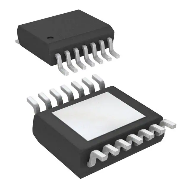
- Part No.:
- MAX14572EUD+T
- Manufacturer:
- Analog Devices Inc./Maxim Integrated
- Category:
- Surge Suppression Ics
- Package:
- 14-TSSOP (0.173", 4.40mm Width) Exposed Pad
- Datasheet:
-
 MAX14572EUD+T.pdf
- Description:
- IC ADJ OV/OC PROTECTOR 14TSSOP
- Quantity:
- Payment:

- Shipping:

Inventory:2,074
Please send an inquiry. Send us your inquiry, and we will respond immediately.
Product details
Overview
The MAX14572EUD+T from Maxim Integrated is a latch-off overvoltage and overcurrent protection IC designed for high-reliability industrial power rail protection. It features 100mΩ (typ) internal FETs, factory-preset 33V (typ) OVLO and 19.2V (typ) UVLO thresholds, programmable current limiting up to 4.2A, and thermal shutdown at +150°C (typ). It operates across 4.5V–36V input and withstands ±40V fault transients, making it suitable for ruggedized industrial equipment with inductive loads.
For engineers reviewing the MAX14572EUD+T datasheet, MAX14572EUD+T pinout, MAX14572EUD+T application, or MAX14572EUD+T equivalent, this page delivers verified functional behavior, exact pin roles, latch-off fault response timing (20.7ms blanking, permanent shutdown until EN/HVEN toggle), reverse-current enable capability via RIEN, and real-world design meaning for each specification - all confirmed against Maxim's official datasheet Rev 4 (7/17).
Technical Context
The MAX14572EUD+T implements a latch-off overcurrent response: upon sustained overload exceeding the SETI-programmed threshold for ≥20.7ms (typ), it permanently disables the internal FETs until EN or HVEN is cycled. Its dual enable architecture (active-high EN and active-low HVEN) allows independent control of power sequencing and fault reset, while the RIEN pin enables reverse-current flow for inductive load freewheeling.
Overvoltage and undervoltage lockout are configurable via external resistor dividers on OVLO and UVLO pins, or use factory presets (33V OVLO, 19.2V UVLO) when those pins are grounded. The device integrates thermal shutdown at +150°C (typ) with 30°C hysteresis and provides open-drain FLAG assertion for all fault conditions - including OVLO/UVLO violation, thermal trip, reverse-current detection, or SETI-to-GND short.
Key Specifications
| Parameter | Value and Actual Design Meaning |
|---|---|
| OVLO Threshold | 33V (typ) factory preset; adjustable 6V–36V externally - sets hard cutoff voltage above which FETs disable to prevent downstream damage. |
| UVLO Threshold | 19.2V (typ) factory preset; adjustable 4.5V–24V externally - ensures minimum valid input before enabling output, preventing brownout operation. |
| Current Limit Range | 0.7A–4.2A (programmable via SETI-to-GND resistor); ±15% accuracy - defines maximum continuous load current before latch-off action. |
| Blanking Time | 20.7ms (typ) - prevents false tripping during inrush or transient surges; only sustained overcurrent beyond this window triggers latch-off. |
| RON | 100mΩ (typ) at ILOAD = 100mA, VIN ≥ 8V - determines conduction loss (PLOSS = I² × RON) and thermal rise under full load. |
| Thermal Shutdown | +150°C (typ) junction temperature - disables FETs immediately upon die overheating; latched state persists until enable reset. |
| Input Fault Tolerance | ±40V on IN pin - protects against severe positive/negative transients (e.g., load dump, reverse battery) without external TVS in many cases. |
Pinout & Package
Package: 14-pin TSSOP-EP (5mm × 6.5mm) with exposed pad connected to GND for thermal enhancement. RoHS-compliant, rated for -40°C to +85°C ambient.
| Pin/Terminal | Circuit Role | Design Meaning |
|---|---|---|
| 1,2,3 IN | High-voltage input terminal | Accepts -40V to +40V; bypassed with 1µF ceramic capacitor for ESD and transient suppression. |
| 4 UVLO | Undervoltage lockout configuration | Ground to enable 19.2V (typ) internal threshold; connect to resistor divider for custom UVLO (4.5V–24V). |
| 5 OVLO | Overvoltage lockout configuration | Ground to enable 33V (typ) internal threshold; connect to resistor divider for custom OVLO (6V–36V). |
| 6 SETI | Current limit programming | Resistor to GND sets ILIM (0.7A–4.2A); unconnected = 0A, shorted to GND = immediate FLAG assert + FET off. |
| 7 GND | Power and signal reference | Primary ground return; EP (exposed pad) must also be soldered to large GND plane for thermal performance. |
| 8 HVEN | High-voltage enable input | Active-low; withstands up to +36V; drive low for normal operation, high to disable (no PCB-level level shift needed). |
| 9 RIEN | Reverse-current enable | Logic-high enables reverse blocking (OUT→IN); logic-low permits reverse current - critical for inductive load recovery. |
| 10 EN | Standard enable input | Active-high; toggling resets latch-off state after overcurrent fault - used for controlled system recovery. |
| 11 FLAG | Fault indicator output | Open-drain; pulls low on OVLO/UVLO breach, thermal trip, reverse-current event, or SETI short - requires external pullup. |
| 12,13,14 OUT | Protected output terminal | Delivers regulated power to load; bypassed with 1µF ceramic cap; supports reverse-current flow when RIEN = low. |
Key Features
| Feature | Design Value |
|---|---|
| Latch-off overcurrent response | Permanently disables FETs after 20.7ms (typ) overload - eliminates repeated cycling, simplifies fault handling in safety-critical systems. |
| Independent dual-enable control | HVEN (high-voltage capable) and EN (standard logic) allow separate power sequencing and fault reset paths - avoids single-point failure in complex systems. |
| Configurable OVLO/UVLO with auto-selection | Internal ±3% accurate thresholds (33V/19.2V) automatically engaged if external resistors set below select voltages - reduces BOM count and layout risk. |
| Reverse-current enable (RIEN) | Disables internal blocking diode function to permit OUT→IN current - essential for energy recovery in solenoid, relay, or motor drive applications. |
| ±40V input fault tolerance | Withstands severe transients without external clamping in many industrial environments - reduces need for TVS diodes and saves board space. |
Applications
| Industrial Motor Drives | Marine Navigation Systems |
|---|---|
Use Scenario: Protecting 24V DC power rails feeding brushed DC motors and solenoids subject to load dump and inductive kickback. IC Role / Device Role / Timing Role: Primary overvoltage/overcurrent latch-off protector placed upstream of motor driver ICs; RIEN enabled to allow reverse current during coil decay. Use Value: Prevents MOSFET destruction during sudden load disconnection; eliminates need for external flyback diodes and reduces thermal stress on downstream components. |
Use Scenario: Securing power inputs in GPS/chartplotter units exposed to marine battery voltage fluctuations and reverse polarity events. IC Role / Device Role / Timing Role: Input supervisor with ±40V fault tolerance and latch-off response - ensures system remains powered only under valid voltage conditions. Use Value: Survives alternator load dump spikes (>35V) and accidental reverse battery connection without damage or false shutdown. |
| Battery-Powered Test Equipment | Factory Automation PLC I/O Modules |
Use Scenario: Power conditioning for portable multimeters and oscilloscope probes operating from Li-ion packs with variable voltage (8V–32V). IC Role / Device Role / Timing Role: Adjustable UVLO (via UVLO pin) ensures operation only above safe battery voltage; OVLO prevents damage from charger overvoltage. Use Value: Extends usable battery range by enabling precise low-voltage cutoff; avoids premature shutdown during high-current pulses. |
Use Scenario: Protecting 24V DC inputs on digital I/O cards subjected to field wiring faults, ESD, and inductive switching noise. IC Role / Device Role / Timing Role: Robust front-end protector with FLAG signaling to PLC controller - reports faults before they propagate to logic circuitry. Use Value: Reduces unplanned downtime by isolating faults at the power entry point; FLAG status enables predictive maintenance logging. |
Equivalent & Alternatives
The following parts are listed as comparable options for similar overvoltage and overcurrent protection applications.
| Alternative Part | Technical Difference | Application Difference | Selection Advice |
|---|---|---|---|
| MAX14571EUD+T | Autoretry (not latch-off) overcurrent response; 600ms (typ) retry period after blanking time. | Suitable where temporary faults must self-clear without operator intervention (e.g., intermittent short circuits). | Select MAX14571EUD+T only if automatic recovery is required; MAX14572EUD+T is preferred for definitive fault isolation. |
| MAX14573EUD+T | Continuous current-limit mode instead of latch-off; maintains regulated output at programmed ILIM during overload. | Used where uninterrupted power delivery is mandatory despite overload (e.g., medical sensor bias rails). | Choose MAX14573EUD+T for constant-current operation; MAX14572EUD+T is optimal when complete shutdown is the safety requirement. |
Compared with MAX14571EUD+T (autoretry) and MAX14573EUD+T (continuous limit), the MAX14572EUD+T provides definitive fault containment - its latch-off behavior ensures no power resumes until a deliberate system-level reset occurs, meeting strict fail-safe requirements in industrial control and marine electronics.
Availability
The MAX14572EUD+T is available at Aetrix Electronics and suitable for industrial motor drives, marine navigation systems, battery-powered test equipment, and factory automation PLC I/O modules requiring stable component supply across extended temperature and high-reliability environments.
Supply support for MAX14572EUD+T includes scheduled delivery planning, volume procurement assistance, BOM continuity management, traceable sourcing, and lifecycle availability coordination for OEM customers, industrial embedded developers, connected-device designers, and electronics production programs.
Manufacturer
Maxim Integrated (now part of Analog Devices) is a semiconductor company specializing in high-performance analog, mixed-signal, and power management ICs for industrial, automotive, and communications applications.
The MAX14572EUD+T belongs to Maxim's adjustable overvoltage/overcurrent protection product line, engineered specifically for robust front-end power rail protection in harsh environments where latch-off fault response, ±40V fault tolerance, and reverse-current flexibility are critical.
FAQ
What fault conditions cause the MAX14572EUD+T to latch off?
The MAX14572EUD+T latches off when an overcurrent condition persists beyond the 20.7ms (typ) blanking time, or when the junction temperature exceeds +150°C (typ). It also asserts FLAG and disables output for OVLO/UVLO violations, reverse-current detection (if RIEN = high), or when SETI is shorted to GND. Latch-off remains active until EN or HVEN is toggled - no automatic recovery occurs.
How do I configure the MAX14572EUD+T for a 28V overvoltage lockout threshold?
To set OVLO = 28V, connect a resistor divider between IN and GND with OVLO pin tied to the midpoint. Using VBG = 1.21V (typ) and R3 = 2.2MΩ (recommended), calculate R4 ≈ 452kΩ via VOVLO = VBG × (1 + R3/R4). Confirm with actual resistor tolerances and validate using the MAX14572EUD+T's ±3% OVLO accuracy spec - no reprogramming or calibration is required.
Does the MAX14572EUD+T support reverse current flow from OUT to IN?
Yes - the MAX14572EUD+T supports reverse current flow when the RIEN pin is driven low (logic 0). This disables internal reverse-blocking circuitry, allowing current to flow from OUT to IN. This feature is essential for inductive load applications (e.g., solenoids, relays) where energy recovery during turn-off prevents damaging voltage spikes.
What is the purpose of the HVEN pin on the MAX14572EUD+T, and how does it differ from EN?
HVEN is an active-low, high-voltage-capable enable input that withstands up to +36V - eliminating the need for external level-shifting circuitry when interfacing with 24V control signals. EN is a standard active-high logic input (VIH ≥ 1.4V). Both can independently reset the latch-off state, but HVEN enables direct integration into higher-voltage industrial control buses without additional components.
Can the MAX14572EUD+T replace the MAX14571EUD+T without hardware changes?
No - although pin-compatible and sharing identical package and basic functionality, the MAX14572EUD+T's latch-off overcurrent response differs fundamentally from the MAX14571EUD+T's autoretry behavior. Substituting them requires validation of system-level fault recovery strategy; unintended permanent shutdown may occur if the application expects automatic retry after transient overloads.
MAX14572EUD+T Specifications
- Product attributes
- Attribute value
- Manufacturer:
- Analog Devices Inc./Maxim Integrated
- Package/Case:
- 14-TSSOP (0.173", 4.40mm Width) Exposed Pad
- Series:
- -
- Packaging:
- Tape & Reel (TR)
- Product Status:
- Active
- Voltage - Clamping:
- -
- Technology:
- Internal Switch
- Number of Circuits:
- 1
- Applications:
- General Purpose
- Grade:
- -
- Qualification:
- -
- Mounting Type:
- Surface Mount
- Supplier Device Package:
- 14-TSSOP-EP
MAX14572EUD+T FAQ
1.How can I place an order for MAX14572EUD+T through Aetrix?
Please submit a Request for Quotation (RFQ) for MAX14572EUD+T on Aetrix. Our sales agent will provide a competitive quotation and guide you through the order confirmation once you accept the terms.
2.Are the price and stock information for MAX14572EUD+T reliable?
The price and inventory of MAX14572EUD+T are updated periodically and may fluctuate due to market conditions. Stock and pricing data are typically refreshed every 24 hours. Quotation validity for MAX14572EUD+T is usually 5 days.
3.What payment methods are accepted for MAX14572EUD+T?
We accept Wire Transfer, PayPal, Credit Card, Western Union, MoneyGram, and Escrow for MAX14572EUD+T transactions.
Note: Certain payment methods may incur a processing fee.
4.How is shipping managed for MAX14572EUD+T?
MAX14572EUD+T orders can be shipped via leading logistics carriers, including DHL, UPS, FedEx, TNT, or Registered Mail.
Once your MAX14572EUD+T order is processed, you will receive an email with the shipment details and tracking number.
Note: Tracking information may take up to 24 hours to appear. Express delivery typically takes 3–5 business days.
5.How can I obtain technical support or documentation for MAX14572EUD+T?
For technical support, including MAX14572EUD+T datasheets, pinout diagrams, or application guidance, please contact our engineering support team. They can provide detailed documentation and assistance for your MAX14572EUD+T requirements.
6.How does Aetrix verify that MAX14572EUD+T is sourced from the original manufacturer or authorized distributors?
All MAX14572EUD+T products on Aetrix are procured from qualified distributors and authorized channels. Our dedicated quality assurance team conducts strict verification, including traceability checks and, if necessary, third-party testing. This ensures that MAX14572EUD+T meets industry standards.
7.What is the process for return or replacement of MAX14572EUD+T?
All MAX14572EUD+T units undergo pre-shipment inspection (PSI). If there is an issue with MAX14572EUD+T, returns or replacements are accepted under the following conditions:
1.Quantity discrepancies, incorrect items, or visible external defects (such as breakage or corrosion), acknowledged by Aetrix.
2.The issue is reported within 90 days of delivery.
3.The MAX14572EUD+T part is unused and in its original packaging.
Return procedure for MAX14572EUD+T:
1.Submit a request within 90 days.
2.Obtain a Return Material Authorization (RMA) from Aetrix.
MAX14572EUD+T Tags
-
TVS3300DRVR
Texas Instruments

-
TCPP01-M12
STMicroelectronics
-
TPD4S214YFFR
Texas Instruments
-
TPD6S300ARUKR
Texas Instruments
-
TBU-CA085-300-WH
Bourns Inc.
-
TBU-CA065-500-WH
Bourns Inc.
-
TBU-CA040-100-WH
Bourns Inc.
-
TBU-CA085-500-WH
Bourns Inc.
-
TBU-CA085-200-WH
Bourns Inc.
-
NX20P0408UKZ
NXP Semiconductors
-
TBU-CA085-100-WH
Bourns Inc.
-
TBU-CA050-300-WH
Bourns Inc.
Tech Hub

A practical engineering guide to 3.3V and 5V logic compatibility, input thresholds, resistor dividers, translator ICs, MOSFET level shifting, I2C pull-ups, timing limits and power-sequencing risks.

The 74HC595 uses push-pull logic outputs, while the TPIC6B595 uses 50 V open-drain DMOS sinks for higher-power loads. This guide compares timing, current limits, 3.3 V interfacing, load wiring, thermal…

The 74HC595 converts serial data into eight stable parallel outputs. This guide covers pin functions, shift and storage timing, OE and MR behavior, drive-current limits, cascading, voltage compatibilit…

A technical comparison of level-sensitive latches and edge-triggered flip-flops, covering timing windows, setup and hold limits, master–slave operation, time borrowing, race-through, HDL inference and…

A D latch stores one bit while Enable controls when data can pass. This reference covers gate-level operation, truth tables, transparency, setup and hold timing, LE versus OE, common ICs and practical …

An SR latch stores one bit through cross-coupled feedback. This engineering reference covers NOR and NAND implementations, truth tables, forbidden-state recovery, gated operation, switch debouncing, fa…

Latch circuits retain one bit through feedback. This technical reference covers SR and D latches, truth tables, transparency, timing limits, latch-versus-flip-flop behavior, applications and common log…

An engineering guide to LED driver operation, constant-current and constant-voltage outputs, linear and switching topologies, dimming, IC selection, calculations, replacement compatibility, and fault c…

Operational amplifier guide covering op amp basics, feedback, ideal vs real op amps, common configurations, buffer circuits, offset, bias current, gain-bandwidth, slew rate, rail-to-rail limits and sel…

Jumper cables guide covering safe connection order, red and black clamp placement, final ground connection, cable gauge, length, clamp quality, copper vs CCA cables, jump starter comparison and battery…


