
 My Inquiry
 My Account


Analog Devices Inc./Maxim Integrated MAX5992AETG+
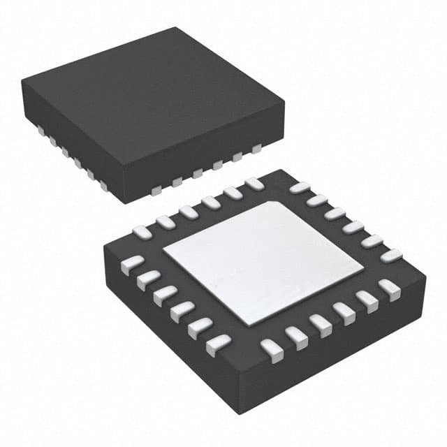
- Part No.:
- MAX5992AETG+
- Manufacturer:
- Analog Devices Inc./Maxim Integrated
- Category:
- Power Over Ethernet (PoE) Controllers
- Package:
- 24-WFQFN Exposed Pad
- Datasheet:
-
 MAX5992AETG+.pdf
- Description:
- IC MULTISOURCE CONTROLLER QFN
- Quantity:
- Payment:

- Shipping:

Inventory:4,046
Please send an inquiry. Send us your inquiry, and we will respond immediately.
Product details
Overview
The MAX5992AETG+ from Maxim Integrated is a high-power, IEEE 802.3af/at-compliant powered device (PD) controller for Power-over-Ethernet systems. It provides detection signature (24.9kΩ), 2-event classification (Class 0–5), active FET bridge control, intelligent maintain power signature (MPS), and dual-level current limiting (800mA/1.9A). It operates with 38.6V PoE UVLO and supports seamless wall adapter switchover in IP security cameras and wireless access nodes.
For engineers reviewing the MAX5992AETG+ datasheet, MAX5992AETG+ pinout, MAX5992AETG+ application, or MAX5992AETG+ equivalent, this page delivers verified technical context, exact pin functions, real-world use cases in UPoE infrastructure, and validated alternative parts for PoE PD design continuity.
Technical Context
The MAX5992AETG+ implements a full IEEE 802.3af/at PD interface with integrated active FET bridge control-enabling bidirectional polarity sensing across VIN1/VIN2 and driving four external MOSFET gates (NDR1/NDR2/PDR1/PDR2). Its detection block uses ΔV/ΔI slope measurement with <10µA input offset current and 25kΩ effective differential resistance to validate the 24.9kΩ signature resistor.
Classification supports both single- and 2-event modes per IEEE 802.3at, with programmable current via RCLS (615Ω for Class 0 → 52.7–63.3mA for Class 5). The device features dual UVLO thresholds (38.6V PoE / 20.8V industrial), 6.5s sleep delay (MAX5992B variant), and ultra-low-power sleep mode sustaining MPS at 10–14mA pulse amplitude and 75% duty cycle.
Key Specifications
| Parameter | Value and Actual Design Meaning |
|---|---|
| PoE UVLO Threshold | 38.6V - sets minimum valid PoE input voltage before power-on mode activation |
| Classification Support | IEEE 802.3af/at Class 0–5 - enables PSE to allocate up to 25.5W (Class 4) or >25.5W (Class 5) |
| Inrush Current Limit | 10–20mV sense threshold - configures ~100–200mA inrush limit with 100mΩ sense resistor |
| Current-Limit Options | 800mA (CL_SEL open) or 1.9A (CL_SEL to VSS) - selects primary overcurrent protection level |
| MPS Pulse Amplitude | 10–14mA - sustains maintain power signature during sleep/ultra-low-power sleep without DC load |
| Operating Temperature | -40°C to +85°C - qualified for industrial and outdoor PoE endpoints including IP cameras and access points |
| Package | 24-pin TQFN (4mm × 4mm) - thermally enhanced for high-power PD applications with θJA = 36°C/W |
Pinout & Package
Package: 24-pin TQFN (4mm × 4mm), exposed pad connected to VSS, rated for -40°C to +85°C operation.
| Pin/Terminal | Circuit Role | Design Meaning |
|---|---|---|
| VDD | Positive supply input | Connects to rectified positive output of active FET bridge; requires ≥68nF bypass capacitor to VSS |
| DET | Detection resistor input | Accepts 24.9kΩ signature resistor to VSS for IEEE-compliant PD detection |
| CLS | Classification resistor input | Sets classification current (0–5) via external resistor (e.g., 615Ω for Class 0) |
| GATE | Isolation MOSFET gate driver | Drives external high-side MOSFET with 8–11V gate drive and 44mA strong pulldown |
| SENSE | Current-sense positive terminal | Connects to source of isolation MOSFET and 100mΩ sense resistor to VSS |
| RTN | Drain-sense input | Monitors MOSFET drain voltage; used for redundancy/FTTH applications and DC-DC ground reference |
| SIG_OK | Signal-OK input/output | Enables 2x2P synchronization; asserts when VIN > VUVLO; pulled up internally to VDD |
| 2EC | 2-event classification/wall adapter detect | 1.5mA current sink activated on Type 2 PSE detection or wall adapter presence (>9V WAD–RTN) |
Key Features
| Feature | Design Value |
|---|---|
| Integrated active FET bridge control | Drives four external MOSFETs (NDR1/NDR2/PDR1/PDR2) with automatic polarity detection across VIN1/VIN2 |
| Intelligent maintain power signature (MPS) | Programmable 10–14mA pulses at 75% duty cycle sustain PoE link during sleep without continuous DC load |
| Selectable UVLO thresholds | 38.6V (PoE) or 20.8V (industrial) via ADJ_UVLO pin - supports medical/industrial auxiliary power requirements |
| Seamless wall adapter transition | WAD_SEL pin configures priority logic: auto-switchover to wall adapter or PoE-first operation with smooth handoff |
| Ultra-low-power sleep mode | Reduces quiescent consumption while maintaining MPS; enabled by SL/ULP combo with 6.5s delay (MAX5992B behavior) |
Applications
| IP Security Cameras (IPC) | Wireless Access Nodes |
|---|---|
Use Scenario: Outdoor PoE-powered camera with local wall adapter backup and thermal management constraints. IC Role / Device Role / Timing Role: PD controller managing IEEE 802.3at classification, active bridge rectification, and MPS maintenance during motion-triggered sleep cycles. Use Value: Enables reliable 25.5W+ power delivery with zero-latency wall adapter fallback and 10–14mA MPS pulses that meet PSE idle-current limits. |
Use Scenario: Dual-PD 2x2P Wi-Fi 6 access point requiring synchronized power-up and redundancy across two Ethernet ports. IC Role / Device Role / Timing Role: PD controller providing SIG_OK interconnection, 2-event classification, and coordinated inrush control for multi-PD synchronization. Use Value: Eliminates PSE port overload via synchronized classification and ensures uninterrupted operation using FTTH/FTTB redundancy mode. |
| Femtocell / Picocell Base Stations | Fiber-to-the-Home (FTTH) Gateways |
Use Scenario: Compact cellular small cell deployed in residential settings with strict power envelope and thermal dissipation limits. IC Role / Device Role / Timing Role: PD controller delivering precise 2-event classification, foldback current limiting, and ultra-low-power sleep with LED status indication. Use Value: Reduces average system power by >40% via ULP sleep mode while maintaining MPS compliance and enabling status LED feedback at 250Hz. |
Use Scenario: Multi-PD redundancy architecture where primary and backup PoE inputs feed a shared DC-DC stage. IC Role / Device Role / Timing Role: PD controller implementing RTN-based redundancy sensing, selectable inrush modes, and back-powering protection. Use Value: Ensures failover within 100ms using RDCY_SEL-configured inrush timing and prevents reverse current flow between redundant PoE sources. |
Equivalent & Alternatives
The following parts are listed as comparable options for similar powered device controller applications.
| Alternative Part | Technical Difference | Application Difference | Selection Advice |
|---|---|---|---|
| MAX5995ETG+ | Supports UPoE (60W), includes integrated hot-swap FET, no active bridge control; 35.4V UVLO (B-grade) | Targeted at higher-power single-PD systems without multi-PD sync or FET bridge needs | Choose MAX5995ETG+ only if UPoE power level and integrated FET outweigh loss of active bridge and SIG_OK sync capability |
| LT4275IMS#PBF | IEEE 802.3at-compliant, 37.5V UVLO, no 2-event classification support, no active FET bridge, no SIG_OK pin | Suitable for basic Class 0–4 PDs without redundancy, MPS optimization, or multi-PD coordination | Choose LT4275IMS#PBF for cost-sensitive, non-redundant PoE endpoints where 2x2P sync and intelligent MPS are not required |
Compared with MAX5992AETG+, MAX5995ETG+ delivers higher UPoE power but lacks active bridge and SIG_OK synchronization, while LT4275IMS#PBF offers simpler implementation at the cost of missing 2-event classification, MPS optimization, and multi-PD coordination features essential for FTTH and high-reliability wireless nodes.
Availability
The MAX5992AETG+ is available at Aetrix Electronics and suitable for IP security cameras, wireless access nodes, femtocell base stations, and fiber-to-the-home gateways requiring stable component supply across industrial temperature ranges and long lifecycle support.
Supply support for MAX5992AETG+ includes scheduled delivery planning, volume procurement assistance, BOM continuity management, traceable sourcing, and lifecycle availability coordination for OEM customers, industrial embedded developers, connected-device designers, and electronics production programs.
Manufacturer
Maxim Integrated (now part of Analog Devices) designs precision analog, mixed-signal, and power management ICs for industrial, communications, and computing applications.
The MAX5992AETG+ belongs to Maxim's Power-over-Ethernet PD controller product line, engineered specifically for high-reliability, multi-PD, and UPoE-compliant endpoints requiring active bridge control, intelligent MPS, and seamless auxiliary power integration.
FAQ
What is the PoE UVLO threshold for the MAX5992AETG+?
The MAX5992AETG+ has a fixed 38.6V PoE under-voltage lockout (UVLO) threshold. This value is specific to the MAX5992A variant and differs from the MAX5992B's 35.4V threshold. The device remains in reset until VIN exceeds 38.6V, ensuring stable power-on sequencing in IEEE 802.3af/at systems. The MAX5992AETG+ datasheet confirms this value under DC Electrical Characteristics, Table "VIN Turn-On Voltage".
Does the MAX5992AETG+ support 2-event classification per IEEE 802.3at?
Yes, the MAX5992AETG+ fully supports IEEE 802.3at 2-event classification. It detects the PSE's first classification voltage (12.5–20.5V), responds with programmed ICLASS, then senses the falling edge below the 10.8V mark threshold to inject IMARK (1.0–3.5mA). This sequence repeats once, enabling Type 2 PSEs to assign higher power classes. The MAX5992AETG+ implements this via dedicated internal logic and the 2EC pin, confirmed in the "2-Event Classification and Detection" section of its datasheet.
How does the MAX5992AETG+ handle wall adapter (WAD) switchover?
The MAX5992AETG+ supports seamless wall adapter switchover using the WAD and WAD_SEL pins. When WAD voltage exceeds 8V relative to RTN, the device disables the isolation MOSFET and activates the 2EC current sink. With WAD_SEL unconnected, it defaults to wall adapter priority; pulling WAD_SEL low enforces PoE-first operation. This behavior is explicitly defined in the Pin Description and General Description sections of the MAX5992AETG+ datasheet.
What package type and thermal performance does the MAX5992AETG+ use?
The MAX5992AETG+ uses a 24-pin TQFN package (4mm × 4mm) with exposed pad connected to VSS. Its thermal resistance is θJA = 36°C/W and θJC = 3°C/W on a four-layer board, enabling reliable operation at full load in industrial environments. The package outline number is 21-0139 and land pattern number is 90-0022, both documented in the MAX5992AETG+ Package Information section.
Can the MAX5992AETG+ drive an external LED for status indication?
Yes, the MAX5992AETG+ integrates an LED driver on the LED pin. During sleep, ultra-low-power sleep, or MPS-active periods, it sources a 250Hz, 25% duty-cycle current (9.6–11.8mA typical) programmable via external RSL resistor. The LED pin must be connected to VSS if unused. This functionality is specified in the "SLEEP/ULTRA-LOW-POWER SLEEP MODE" table of the MAX5992AETG+ DC Electrical Characteristics.
MAX5992AETG+ Specifications
- Product attributes
- Attribute value
- Manufacturer:
- Analog Devices Inc./Maxim Integrated
- Series:
- -
- Package/Case:
- 24-WFQFN Exposed Pad
- Packaging:
- Tube
- Product Status:
- Active
- Type:
- Controller (PD)
- Number of Channels:
- 1
- Power - Max:
- -
- Internal Switch(s):
- Yes
- Auxiliary Sense:
- Yes
- Standards:
- 802.3at (PoE+), 802.3af (PoE)
- Voltage - Supply:
- 60V
- Current - Supply:
- 1.5mA
- Operating Temperature:
- -40°C ~ 85°C
- Mounting Type:
- Surface Mount
- Supplier Device Package:
- 24-TQFN (4x4)
MAX5992AETG+ FAQ
1.How can I place an order for MAX5992AETG+ through Aetrix?
Please submit a Request for Quotation (RFQ) for MAX5992AETG+ on Aetrix. Our sales agent will provide a competitive quotation and guide you through the order confirmation once you accept the terms.
2.Are the price and stock information for MAX5992AETG+ reliable?
The price and inventory of MAX5992AETG+ are updated periodically and may fluctuate due to market conditions. Stock and pricing data are typically refreshed every 24 hours. Quotation validity for MAX5992AETG+ is usually 5 days.
3.What payment methods are accepted for MAX5992AETG+?
We accept Wire Transfer, PayPal, Credit Card, Western Union, MoneyGram, and Escrow for MAX5992AETG+ transactions.
Note: Certain payment methods may incur a processing fee.
4.How is shipping managed for MAX5992AETG+?
MAX5992AETG+ orders can be shipped via leading logistics carriers, including DHL, UPS, FedEx, TNT, or Registered Mail.
Once your MAX5992AETG+ order is processed, you will receive an email with the shipment details and tracking number.
Note: Tracking information may take up to 24 hours to appear. Express delivery typically takes 3–5 business days.
5.How can I obtain technical support or documentation for MAX5992AETG+?
For technical support, including MAX5992AETG+ datasheets, pinout diagrams, or application guidance, please contact our engineering support team. They can provide detailed documentation and assistance for your MAX5992AETG+ requirements.
6.How does Aetrix verify that MAX5992AETG+ is sourced from the original manufacturer or authorized distributors?
All MAX5992AETG+ products on Aetrix are procured from qualified distributors and authorized channels. Our dedicated quality assurance team conducts strict verification, including traceability checks and, if necessary, third-party testing. This ensures that MAX5992AETG+ meets industry standards.
7.What is the process for return or replacement of MAX5992AETG+?
All MAX5992AETG+ units undergo pre-shipment inspection (PSI). If there is an issue with MAX5992AETG+, returns or replacements are accepted under the following conditions:
1.Quantity discrepancies, incorrect items, or visible external defects (such as breakage or corrosion), acknowledged by Aetrix.
2.The issue is reported within 90 days of delivery.
3.The MAX5992AETG+ part is unused and in its original packaging.
Return procedure for MAX5992AETG+:
1.Submit a request within 90 days.
2.Obtain a Return Material Authorization (RMA) from Aetrix.
MAX5992AETG+ Tags

-
TPS2378DDAR
Texas Instruments
-
TPS23753APWR
Texas Instruments
-
TPS23756PWPR
Texas Instruments
-
TPS23750PWPR
Texas Instruments
-
MP8007GV-Z
Monolithic Power Systems Inc.
-
TPS23861PWR
Texas Instruments

-
TPS23753PWR
Texas Instruments
-
PD69201ILD-TR
Microchip Technology
-
SI3402-B-GM
Skyworks Solutions Inc.
-
SI3402-B-GMR
Skyworks Solutions Inc.
-
SI34071-A01-GMR
Skyworks Solutions Inc.
-
SI3404-A-GMR
Skyworks Solutions Inc.
Tech Hub

A practical engineering guide to 3.3V and 5V logic compatibility, input thresholds, resistor dividers, translator ICs, MOSFET level shifting, I2C pull-ups, timing limits and power-sequencing risks.

The 74HC595 uses push-pull logic outputs, while the TPIC6B595 uses 50 V open-drain DMOS sinks for higher-power loads. This guide compares timing, current limits, 3.3 V interfacing, load wiring, thermal…

The 74HC595 converts serial data into eight stable parallel outputs. This guide covers pin functions, shift and storage timing, OE and MR behavior, drive-current limits, cascading, voltage compatibilit…

A technical comparison of level-sensitive latches and edge-triggered flip-flops, covering timing windows, setup and hold limits, master–slave operation, time borrowing, race-through, HDL inference and…

A D latch stores one bit while Enable controls when data can pass. This reference covers gate-level operation, truth tables, transparency, setup and hold timing, LE versus OE, common ICs and practical …

An SR latch stores one bit through cross-coupled feedback. This engineering reference covers NOR and NAND implementations, truth tables, forbidden-state recovery, gated operation, switch debouncing, fa…

Latch circuits retain one bit through feedback. This technical reference covers SR and D latches, truth tables, transparency, timing limits, latch-versus-flip-flop behavior, applications and common log…

An engineering guide to LED driver operation, constant-current and constant-voltage outputs, linear and switching topologies, dimming, IC selection, calculations, replacement compatibility, and fault c…

Operational amplifier guide covering op amp basics, feedback, ideal vs real op amps, common configurations, buffer circuits, offset, bias current, gain-bandwidth, slew rate, rail-to-rail limits and sel…

Jumper cables guide covering safe connection order, red and black clamp placement, final ground connection, cable gauge, length, clamp quality, copper vs CCA cables, jump starter comparison and battery…


