
 My Inquiry
 My Account


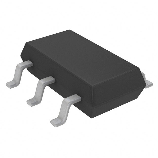
Analog Devices Inc./Maxim Integrated MAX9930EUA+T

- Part No.:
- MAX9930EUA+T
- Manufacturer:
- Analog Devices Inc./Maxim Integrated
- Category:
- RF Detectors
- Package:
- 8-TSSOP, 8-MSOP (0.118", 3.00mm Width)
- Datasheet:
-
 MAX9930EUA+T.pdf
- Description:
- IC RF DETECT 2MHZ-1.6GHZ 8UMAX
- Quantity:
- Payment:

- Shipping:

Inventory:3,531
Please send an inquiry. Send us your inquiry, and we will respond immediately.
Product details
Overview
MAX9930EUA+T from Maxim Integrated is a low-power, 2MHz–1.6GHz logarithmic amplifier designed for RF power amplifier (PA) control loops in wireless transmitters. It delivers 45dB dynamic range, -58dBV to -13dBV input voltage range (-45dBm to 0dBm at 50Ω), 25–29mV/dB logarithmic slope, and operates from -40°C to +85°C with 7mA supply current at 5V. It serves as a complete RF-detecting PA controller in cellular handsets and GPON-CATV triplexors.
For engineers reviewing the MAX9930EUA+T datasheet, MAX9930EUA+T pinout, MAX9930EUA+T application, or MAX9930EUA+T equivalent, key selection criteria include its logarithmic intercept (-61dBm typ at 2MHz), fast 70ns 10dB step response, 10mA output sourcing capability, temperature-stable linear-in-dB output, and μMAX-8 package compatibility with RF front-end layout constraints.
Technical Context
The MAX9930EUA+T implements a five-stage logarithmic amplifier strip-four 10dB gain stages plus a pre-amplifier detector-feeding summed rectified currents into a high-gain transconductance (gm) stage. Its transfer function is defined by logarithmic slope (25–29mV/dB) and intercept (-61dBm typ), enabling precise RF power calculation via RFIN = (SET / SLOPE) + IP.
It operates in controller mode: RFIN accepts coupled PA output, SET sets target power level (0.35V–1.45V), CLPF sets loop bandwidth via external capacitor, and OUT drives the PA's gain-control input with rail-to-rail swing (150mV to VCC–250mV) while sourcing up to 10mA. SHDN enables shutdown with 13μA quiescent current and 2.5μs power-on delay.
Key Specifications
| Parameter | Value and Actual Design Meaning |
|---|---|
| RF Frequency Range | 2MHz to 1.6GHz - supports GSM, CDMA, TDMA, GPRS, and GPON-CATV upstream/downstream bands |
| Input Voltage Range | -58dBV to -13dBV - covers -45dBm to 0dBm at 50Ω, eliminating need for external attenuators in low-power PA control |
| Logarithmic Slope | 25–29mV/dB (typ 27mV/dB at 2MHz) - defines resolution and linearity of power measurement across temperature and frequency |
| Dynamic Range | 45dB (±1dB conformance) - enables accurate RSSI and closed-loop PA control over wide signal variation |
| Supply Current | 7mA at 5V - enables low-power operation in battery-powered terminals and portable RF modules |
| Shutdown Current | 13μA (typ) - allows deep power gating during idle periods without compromising wake-up latency |
| Output Drive | 10mA sourcing capability - directly interfaces with standard PA gain-control inputs without buffer amplification |
Pinout & Package
The MAX9930EUA+T is housed in an 8-pin μMAX® package (2.1mm × 2.1mm, 0.5mm pitch), optimized for RF layout with minimal parasitic inductance and ground plane continuity.
| Pin/Terminal | Circuit Role | Design Meaning |
|---|---|---|
| RFIN | RF Input | AC-coupled RF port accepting 2MHz–1.6GHz signals; requires external series capacitor and 50Ω shunt for impedance matching |
| SHDN | Shutdown Control | Active-low logic input; pulling ≤0.8V places device in 13μA shutdown state with glitch-free 2.5μs power-on delay on OUT |
| SET | Set-Point Reference | Analog input (0.35V–1.45V) defining target RF power level; determines PA output via log transfer function |
| CLPF | Control Loop Filter | Connection point for external capacitor to ground; sets dominant pole of PA control loop bandwidth (e.g., 100nF → ~20MHz BW) |
| GND | Ground | Dedicated analog ground reference; must be low-impedance and isolated from digital/RF return paths |
| N.C. | No Connection | Pin 6 is unconnected internally; must remain floating or grounded per layout best practices |
| OUT | PA Gain-Control Output | Voltage-output stage sourcing up to 10mA; swings 150mV to VCC–250mV to drive variable-gain PA bias inputs |
| VCC | Supply Voltage | 2.7V–5.25V analog supply; requires local 0.1μF ceramic bypass capacitor to GND for RF stability |
Key Features
| Feature | Design Value |
|---|---|
| Complete RF-Detecting PA Controller | Integrates detector strip, gm stage, and buffered output - eliminates discrete diode detector + op-amp + DAC complexity in closed-loop PA design |
| Temperature-Stable Linear-in-dB Response | ±0.5dB max error over -40°C to +85°C - ensures consistent RSSI accuracy and power control without calibration drift |
| Fast 10dB Step Response | 70ns rise time - enables rapid AGC correction for burst-mode transmissions (e.g., TDMA, OOK) |
| Voltage-Referenced Input Ranges | -58dBV to -13dBV input span - matches typical directional coupler outputs without external scaling or attenuation |
| Low-Power Shutdown Mode | 13μA typical shutdown current - extends battery life in intermittent-transmit applications like IoT sensors and handheld terminals |
Applications
| Cellular Handsets (GSM/TDMA) | RSSI for GPON-CATV Triplexors |
|---|---|
Use Scenario: Real-time transmit power regulation in dual-band GSM handsets using directional coupler feedback. IC Role / Device Role / Timing Role: MAX9930EUA+T acts as the core RF power detector and analog controller, converting coupled PA output to a DC voltage that adjusts PA bias in closed loop. Use Value: Enables ±0.5dB transmit power accuracy across temperature and battery voltage variation, meeting 3GPP output power mask requirements. | Use Scenario: Downstream RF power monitoring in GPON optical line terminals with integrated CATV video overlay. IC Role / Device Role / Timing Role: MAX9930EUA+T measures composite RF video signal amplitude (47–862MHz) and provides stable DC output for automatic level control (ALC). Use Value: Delivers 45dB dynamic range and <±1dB log conformance - maintains consistent downstream video SNR despite fiber loss fluctuations. |
| Transmitter Power Measurement | Low-Frequency RF OOK/ASK Applications |
Use Scenario: Production-line RF power calibration of WiFi/BT modules using swept CW tones. IC Role / Device Role / Timing Role: MAX9930EUA+T functions as a precision RF detector feeding a microcontroller ADC, replacing costly spectrum analyzers for pass/fail testing. Use Value: Provides traceable -45dBm to 0dBm measurement with 25mV/dB slope - reduces test fixture cost and cycle time vs. external instrumentation. | Use Scenario: ASK/OOK envelope detection in sub-GHz ISM band remote controls and sensor nodes. IC Role / Device Role / Timing Role: MAX9930EUA+T serves as a wide-dynamic-range demodulator, converting modulated RF bursts into clean baseband logic-level pulses. Use Value: Achieves 70ns response and 45dB range - reliably recovers data from low-SNR, duty-cycled transmissions without AGC settling delays. |
Equivalent & Alternatives
The following parts are listed as comparable options for similar RF-detecting controller applications.
| Alternative Part | Technical Difference | Application Difference | Selection Advice |
|---|---|---|---|
| MAX9931EUA+T | Wider input range: -48dBV to -3dBV (-35dBm to +10dBm); higher RF input tolerance (+16dBm max) | Better suited for medium-power PAs (e.g., LTE UE power class 3) where MAX9930EUA+T would saturate | Select when controlling PAs with >0dBm coupled output; verify CLPF compensation for altered loop dynamics |
| AD8313ARMZ | 20MHz–2.5GHz range; 60dB dynamic range; 2.7V–5.5V supply; 5.5mA ICC; no SET/CLPF pins - pure detector only | Lacks integrated controller functionality (no SET input or OUT drive); requires external DAC and op-amp for closed-loop use | Choose for wideband detector-only roles or when system already includes digital control; not drop-in for MAX9930EUA+T controller topology |
Compared with MAX9931EUA+T and AD8313ARMZ, the MAX9930EUA+T offers optimal balance of low-end sensitivity (-45dBm), compact μMAX-8 footprint, and full analog controller integration - making it ideal for cost-sensitive, space-constrained GSM/GPRS handset designs requiring self-contained PA regulation.
Availability
MAX9930EUA+T is available at Aetrix Electronics and suitable for cellular handset manufacturing, GPON-CATV infrastructure, and RF test equipment requiring stable component supply, RoHS-compliant packaging, and long-term production continuity.
Supply support for MAX9930EUA+T includes scheduled delivery planning, volume procurement assistance, BOM continuity management, traceable sourcing, and lifecycle availability coordination for OEM customers, industrial embedded developers, connected-device designers, and electronics production programs.
Manufacturer
Maxim Integrated (now part of Analog Devices) is a semiconductor company specializing in precision analog, mixed-signal, and RF ICs for industrial, communications, and consumer applications.
The MAX9930–MAX9933 family was engineered specifically for RF power control in wireless transmitters - delivering integrated logarithmic detection, temperature-stable transfer functions, and analog loop interface capability in miniature packages.
FAQ
What is the operating temperature range for the MAX9930EUA+T?
The MAX9930EUA+T is specified for continuous operation from -40°C to +85°C. All electrical characteristics-including logarithmic slope, intercept, and conformance error-are guaranteed across this full industrial temperature range, with typical error maintained within ±0.5dB at -40°C and +85°C per the datasheet's LOG CONFORMANCE vs. TEMPERATURE plots. This makes the MAX9930EUA+T suitable for deployment in outdoor base stations and automotive telematics units.
How does the MAX9930EUA+T interface with a power amplifier in a closed-loop control system?
The MAX9930EUA+T interfaces directly: RFIN receives a coupled sample of the PA output via directional coupler and AC-coupling capacitor; SET accepts a DC voltage (0.35V–1.45V) from a DAC or potentiometer defining target power; CLPF connects to an external capacitor setting loop bandwidth; and OUT drives the PA's gain-control pin with 10mA sourcing capability. The MAX9930EUA+T continuously compares detected RF level to SET and adjusts OUT to maintain constant output power.
What is the purpose of the CLPF pin on the MAX9930EUA+T?
The CLPF pin on the MAX9930EUA+T connects to an external capacitor to ground, forming the dominant pole of the PA control loop. Its value (e.g., 100nF) sets small-signal bandwidth (~20MHz) and influences transient response-smaller capacitors increase bandwidth but risk instability if PA control path phase lag is excessive. The MAX9930EUA+T's internal gm stage and buffer ensure predictable loop behavior without requiring external compensation components.
Can the MAX9930EUA+T be used with a 3.3V supply?
Yes, the MAX9930EUA+T operates from 2.7V to 5.25V, making 3.3V fully compatible. At 3.3V, supply current remains ~6.8mA (per SUPPLY CURRENT vs. SUPPLY VOLTAGE plot), logarithmic slope holds at 25–29mV/dB, and OUT retains full 10mA sourcing capability with output swing from 150mV to ~3.05V. The 3.3V operation is commonly used in modern baseband ICs and low-voltage RF modules interfacing with the MAX9930EUA+T.
What is the maximum RF input power the MAX9930EUA+T can handle?
The MAX9930EUA+T has an absolute maximum RF input rating of +6dBm at RFIN. Exceeding this risks permanent damage. For reliable operation within specifications, the usable input power range is -45dBm to 0dBm (i.e., -58dBV to -13dBV at 50Ω), where logarithmic conformance error stays within ±1dB. Applications requiring higher input levels (e.g., +10dBm) should use the MAX9931EUA+T variant instead.
MAX9930EUA+T Specifications
- Product attributes
- Attribute value
- Manufacturer:
- Analog Devices Inc./Maxim Integrated
- Series:
- -
- Packaging:
- Tape & Reel (TR)
- Product Status:
- Active
- Frequency:
- 2MHz ~ 1.6GHz
- RF Type:
- Cellular, TDMA, CDMA, GPRS, GSM
- Input Range:
- -45dBm ~ 0dBm
- Accuracy:
- ±1dB
- Voltage - Supply:
- 2.7V ~ 5.25V
- Mounting Type:
- 12 mA
- Supplier Device Package:
- Surface Mount
- Current - Supply:
- 8-uMAX/uSOP
MAX9930EUA+T FAQ
1.How can I place an order for MAX9930EUA+T through Aetrix?
Please submit a Request for Quotation (RFQ) for MAX9930EUA+T on Aetrix. Our sales agent will provide a competitive quotation and guide you through the order confirmation once you accept the terms.
2.Are the price and stock information for MAX9930EUA+T reliable?
The price and inventory of MAX9930EUA+T are updated periodically and may fluctuate due to market conditions. Stock and pricing data are typically refreshed every 24 hours. Quotation validity for MAX9930EUA+T is usually 5 days.
3.What payment methods are accepted for MAX9930EUA+T?
We accept Wire Transfer, PayPal, Credit Card, Western Union, MoneyGram, and Escrow for MAX9930EUA+T transactions.
Note: Certain payment methods may incur a processing fee.
4.How is shipping managed for MAX9930EUA+T?
MAX9930EUA+T orders can be shipped via leading logistics carriers, including DHL, UPS, FedEx, TNT, or Registered Mail.
Once your MAX9930EUA+T order is processed, you will receive an email with the shipment details and tracking number.
Note: Tracking information may take up to 24 hours to appear. Express delivery typically takes 3–5 business days.
5.How can I obtain technical support or documentation for MAX9930EUA+T?
For technical support, including MAX9930EUA+T datasheets, pinout diagrams, or application guidance, please contact our engineering support team. They can provide detailed documentation and assistance for your MAX9930EUA+T requirements.
6.How does Aetrix verify that MAX9930EUA+T is sourced from the original manufacturer or authorized distributors?
All MAX9930EUA+T products on Aetrix are procured from qualified distributors and authorized channels. Our dedicated quality assurance team conducts strict verification, including traceability checks and, if necessary, third-party testing. This ensures that MAX9930EUA+T meets industry standards.
7.What is the process for return or replacement of MAX9930EUA+T?
All MAX9930EUA+T units undergo pre-shipment inspection (PSI). If there is an issue with MAX9930EUA+T, returns or replacements are accepted under the following conditions:
1.Quantity discrepancies, incorrect items, or visible external defects (such as breakage or corrosion), acknowledged by Aetrix.
2.The issue is reported within 90 days of delivery.
3.The MAX9930EUA+T part is unused and in its original packaging.
Return procedure for MAX9930EUA+T:
1.Submit a request within 90 days.
2.Obtain a Return Material Authorization (RMA) from Aetrix.
MAX9930EUA+T Tags
-
LMH2110TMX/NOPB
Texas Instruments
-
MAX2204EXK+T
Analog Devices Inc./Maxim Integrated
-
LMV221SD/NOPB
Texas Instruments
-
LTC5505-2ES5#TRMPBF
Analog Devices Inc.
-
LTC5505-1ES5#TRMPBF
Analog Devices Inc.
-
AD8314ACPZ-RL7
Analog Devices Inc.
-
ADL5506ACBZ-R7
Analog Devices Inc.
-
AD8312ACBZ-P7
Analog Devices Inc.
-
MAX4003EUA+T
Analog Devices Inc./Maxim Integrated
-
LTC5530ES6#TRMPBF
Analog Devices Inc.
-
LTC5507ES6#TRMPBF
Analog Devices Inc.
-
LTC5507ES6#TRPBF
Analog Devices Inc.
Tech Hub

A practical engineering guide to 3.3V and 5V logic compatibility, input thresholds, resistor dividers, translator ICs, MOSFET level shifting, I2C pull-ups, timing limits and power-sequencing risks.

The 74HC595 uses push-pull logic outputs, while the TPIC6B595 uses 50 V open-drain DMOS sinks for higher-power loads. This guide compares timing, current limits, 3.3 V interfacing, load wiring, thermal…

The 74HC595 converts serial data into eight stable parallel outputs. This guide covers pin functions, shift and storage timing, OE and MR behavior, drive-current limits, cascading, voltage compatibilit…

A technical comparison of level-sensitive latches and edge-triggered flip-flops, covering timing windows, setup and hold limits, master–slave operation, time borrowing, race-through, HDL inference and…

A D latch stores one bit while Enable controls when data can pass. This reference covers gate-level operation, truth tables, transparency, setup and hold timing, LE versus OE, common ICs and practical …

An SR latch stores one bit through cross-coupled feedback. This engineering reference covers NOR and NAND implementations, truth tables, forbidden-state recovery, gated operation, switch debouncing, fa…

Latch circuits retain one bit through feedback. This technical reference covers SR and D latches, truth tables, transparency, timing limits, latch-versus-flip-flop behavior, applications and common log…

An engineering guide to LED driver operation, constant-current and constant-voltage outputs, linear and switching topologies, dimming, IC selection, calculations, replacement compatibility, and fault c…

Operational amplifier guide covering op amp basics, feedback, ideal vs real op amps, common configurations, buffer circuits, offset, bias current, gain-bandwidth, slew rate, rail-to-rail limits and sel…

Jumper cables guide covering safe connection order, red and black clamp placement, final ground connection, cable gauge, length, clamp quality, copper vs CCA cables, jump starter comparison and battery…


