
 My Inquiry
 My Account


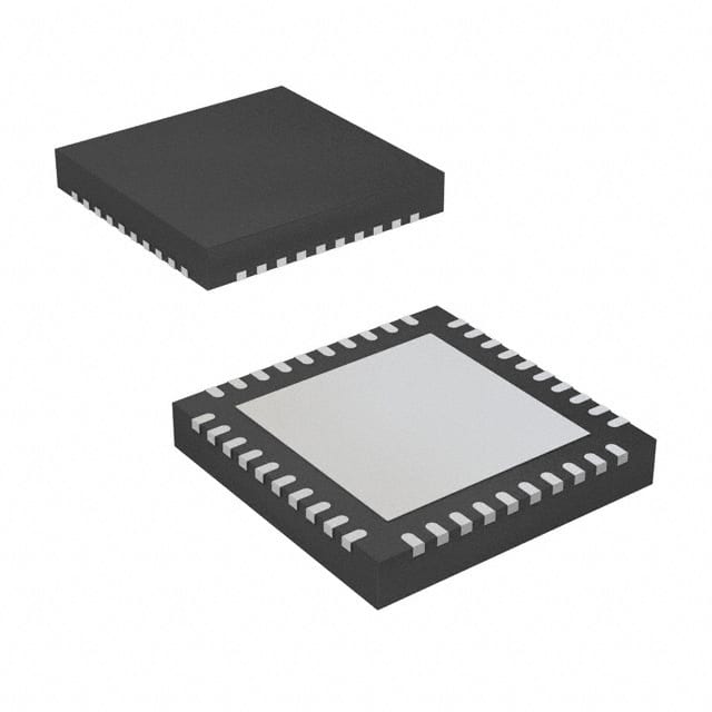
Microchip Technology MD1715K6-G-M935
- Part No.:
- MD1715K6-G-M935
- Manufacturer:
- Microchip Technology
- Category:
- Power Management - Specialized
- Package:
- 40-VFQFN Exposed Pad
- Datasheet:
-
 MD1715K6-G-M935.pdf
- Description:
- IC ULTRASOUND DRIVER 40VQFN
- Quantity:
- Payment:

- Shipping:

Inventory:2,175
Please send an inquiry. Send us your inquiry, and we will respond immediately.
Product details
Overview
MD1715K6-G-M935 from Microchip Technology is a 2-channel logic controller IC for high-speed ultrasound transmit pulsers, integrating 12 matched low-impedance MOSFET gate drivers with ±4.75–12.9V gate drive voltage, 2A peak source/sink current, and 6.5 ns rise/fall time (1 nF load). It pairs exclusively with TC8020 to form a five-level pulser system used in medical ultrasound imaging and non-destructive testing.
For engineers reviewing the MD1715K6-G-M935 datasheet, MD1715K6-G-M935 pinout, MD1715K6-G-M935 application, or MD1715K6-G-M935 equivalent, this page delivers verified electrical specs, channel-matched timing performance (±2 ns delay matching), dual-supply gate drive architecture (VDD1/VDD2, AVSS/VSS), and functional truth tables for SEL/POS/NEG control logic per channel.
Technical Context
The MD1715K6-G-M935 implements two independent 3-pair gate driver channels (A and B), each driving three P/N-MOSFET pairs in the companion TC8020 output stage. Its control logic accepts 1.8–3.3V CMOS inputs (SELA/POSA/NEGA, SELB/POSB/NEGB) and features smart logic threshold with VLL/EN dual-function enable/reference pin.
It operates across dual analog supplies: AVDD/AVSS (±12.9V max) for internal circuitry and separate VDD1/VDD2 (±12.9V) and VSS (–12.9V) for gate driver stages - enabling independent voltage tuning per driver pair group. Propagation delay is 10 ns with ±2 ns channel-to-channel matching and 1 ns rise/fall time matching per channel.
Key Specifications
| Parameter | Value and Actual Design Meaning |
|---|---|
| Gate Drive Voltage Range | ±4.75V to ±12.9V - supports flexible high-voltage pulser biasing for piezoelectric transducers |
| Peak Output Current | 2A source/sink - drives TC8020's P/N-MOSFET pairs with sufficient transient current for fast switching |
| Rise/Fall Time | 6.5 ns @ 1 nF load - enables >100 MHz effective edge rates required for high-resolution ultrasound waveforms |
| Propagation Delay | 10 ns - ensures precise timing alignment between logic input and gate output transitions |
| Delay Matching | ±2 ns channel-to-channel - critical for coherent multi-element beamforming in phased-array ultrasound systems |
| Logic Interface | 1.8V–3.3V CMOS - compatible with FPGA/CPLD control without level-shifting |
| Operating Temp | 0°C to +125°C junction - validated for industrial and medical equipment thermal environments |
Pinout & Package
MD1715K6-G-M935 is housed in a 40-lead QFN (VQFN) package with exposed thermal pad (K6 designation), RoHS-compliant matte tin finish, and 3000-unit reel packaging (M935).
| Pin/Terminal | Circuit Role | Design Meaning |
|---|---|---|
| SELA, SELB | Channel A/B select control | Determines active state of three driver pairs per channel per truth table (Table 3-1/3-2) |
| POSA, POSB | Positive output enable | Activates P-channel drivers (OP1/OP2/OP3) when asserted with SEL and NEG |
| NEGA, NEGB | Negative output enable | Activates N-channel drivers (ON1/ON2/ON3) when asserted with SEL and POS |
| VLL/EN | Logic reference & chip enable | 1.8–3.3V logic supply input; low = disable all outputs, high = enable operation |
| OP1A–OP3A, OP1B–OP3B | P-channel gate driver outputs | Drive gates of TC8020's upper-side P-MOSFETs; each rated for ±2A peak |
| ON1A–ON3A, ON1B–ON3B | N-channel gate driver outputs | Drive gates of TC8020's lower-side N-MOSFETs; matched timing with corresponding OPx |
| VDD1, VDD2, VSS, AVDD, AVSS | Multi-rail power supplies | VDD1 powers OP2/ON2/ON3 groups; VDD2 powers OP1/ON1; VSS/AVSS provide negative bias for damping drivers (OP3/ON3) |
| GND, AGND | Power and analog ground | Separate ground returns minimize noise coupling between digital control and high-current gate drive paths |
| Thermal Pad | IC substrate connection | Must be externally connected to AVSS plane for thermal dissipation and substrate bias stability |
Key Features
| Feature | Design Value |
|---|---|
| 12 matched gate drivers | Three P/N pairs per channel with ≤1 ns rise/fall matching - enables uniform pulse generation across transducer elements |
| Smart logic threshold | Input thresholds scale with VLL (0.2VLL low / 0.8VLL high) - maintains noise margin across 1.8–3.3V logic supply range |
| Low-inductance QFN package | 40-lead VQFN with thermal pad - reduces parasitic inductance for clean 2A switching edges and EMI control |
| Dual independent gate supplies | VDD1 and VDD2 configurable at different voltages - allows optimization of drive strength vs. power loss per FET pair group |
| Chip enable with power-down mode | VLL/EN pin disables all drivers; reduces VDD1/VDD2 quiescent current to ≤25 µA - supports low-power idle states |
Applications
| Medical Ultrasound Imaging | Piezoelectric Transducer Drivers |
|---|---|
Use Scenario: Phased-array ultrasound probe with 128+ elements requiring synchronized five-level transmit pulses for beam steering and focusing. IC Role / Device Role / Timing Role: Logic controller generating precisely timed, matched gate signals for TC8020's 12 FET pairs - defines pulse amplitude, polarity, and duration per element. Use Value: ±2 ns channel matching ensures sub-wavelength timing coherence across array elements, directly improving axial resolution and image contrast. |
Use Scenario: High-frequency (>10 MHz) immersion transducer system for material characterization using burst-mode excitation. IC Role / Device Role / Timing Role: Gate driver interface translating FPGA logic commands into high-current, high-slew-rate gate voltages for TC8020's P/N-FET stacks. Use Value: 6.5 ns rise/fall time enables <10 ns pulse edge definition, supporting narrow-bandwidth pulse compression and improved signal-to-noise ratio. |
| Metal Flaw Detection | Non-destructive Testing (NDT) |
Use Scenario: Portable ultrasonic flaw detector scanning weld seams in steel pipelines using contact transducers. IC Role / Device Role / Timing Role: Transmit pulser controller managing dual-channel excitation sequences with variable pulse polarity and damping control (OP3/ON3). Use Value: Independent VDD1/VDD2 and VSS rails allow dynamic adjustment of drive voltage per channel - optimizing penetration depth vs. resolution trade-off on-the-fly. |
Use Scenario: Automated NDT system inspecting aerospace composites with programmable pulse echo and through-transmission modes. IC Role / Device Role / Timing Role: High-speed logic interface coordinating multi-channel pulsers and receive path gating via SEL/POS/NEG truth tables. Use Value: 10 ns propagation delay and matched timing reduce jitter-induced artifacts in time-of-flight measurements, improving defect localization accuracy to ±0.1 mm. |
Equivalent & Alternatives
The following parts are listed as comparable options for similar high-speed multi-channel gate driver applications.
| Alternative Part | Technical Difference | Application Difference | Selection Advice |
|---|---|---|---|
| TC8020 | Companion output-stage IC with six P/N-MOSFET pairs; requires MD1715K6-G-M935 for logic control | Not a standalone replacement - only functions as output stage paired with MD1715K6-G-M935 | Select TC8020 only when building full five-level pulser system; MD1715K6-G-M935 must be used as controller |
| MD1810 | Single-channel variant with identical 6-driver architecture, same timing specs, and shared pin-compatible footprint | Suitable for half-density systems or modular designs where channel count can be scaled independently | Choose MD1810 for cost-sensitive single-channel implementations; verify layout compatibility with K6 package and thermal pad routing |
Compared with TC8020 and MD1810, MD1715K6-G-M935 uniquely provides dual-channel control with 12 matched drivers in one die - eliminating inter-device skew and reducing PCB area versus two MD1810s, while enabling true synchronized five-level waveform synthesis essential for medical imaging.
Availability
MD1715K6-G-M935 is available at Aetrix Electronics and suitable for medical ultrasound imaging systems, non-destructive testing equipment, and piezoelectric transducer driver modules requiring stable component supply, long-term lifecycle support, and traceable RoHS-compliant sourcing.
Supply support for MD1715K6-G-M935 includes scheduled delivery planning, volume procurement assistance, BOM continuity management, traceable sourcing, and lifecycle availability coordination for OEM customers, industrial embedded developers, connected-device designers, and electronics production programs.
Manufacturer
Microchip Technology is a U.S.-based semiconductor manufacturer specializing in microcontrollers, analog devices, and timing solutions, with ISO/TS-16949-certified wafer fabrication and design centers worldwide.
The MD1715K6-G-M935 belongs to Microchip's high-speed ultrasound pulser IC family, engineered specifically for precision timing-critical medical and industrial NDT applications requiring multi-level voltage synthesis and sub-nanosecond channel matching.
FAQ
What is the primary function of MD1715K6-G-M935 in an ultrasound system?
The MD1715K6-G-M935 serves as the logic controller for a five-level high-speed transmit pulser, generating precisely timed, matched gate drive signals for the TC8020's 12 MOSFETs. It translates low-voltage CMOS inputs (SELA/POSA/NEGA etc.) into high-current, high-voltage gate pulses - enabling programmable pulse amplitude, polarity, and damping control essential for beamforming in medical ultrasound imaging and NDT systems. Its ±2 ns channel matching directly impacts image resolution.
Does MD1715K6-G-M935 require external level shifting for 1.8V logic inputs?
No, MD1715K6-G-M935 does not require external level shifting for 1.8V logic inputs. Its logic interface supports 1.8V–3.3V CMOS levels natively, with input thresholds defined as 0.2×VLL (low) and 0.8×VLL (high). When VLL = 1.8V, VIH is 1.44V min and VIL is 0.36V max - ensuring robust noise margin and direct interfacing with 1.8V FPGAs or ASICs without additional circuitry.
How does the VLL/EN pin operate in MD1715K6-G-M935?
The VLL/EN pin on MD1715K6-G-M935 is a dual-function terminal: it supplies the logic reference voltage (1.8–3.3V) and acts as the global chip enable. When pulled low (<0.3V), it disables all 12 gate drivers and reduces quiescent currents (e.g., IVDD1Q ≤25 µA). When high (≥0.8×VLL), it enables normal operation. This integrated design eliminates need for separate enable logic and simplifies power sequencing in pulser subsystems.
Can MD1715K6-G-M935 drive MOSFETs directly without TC8020?
No, MD1715K6-G-M935 cannot drive power MOSFETs directly without TC8020. It is a gate driver controller - its OPx/ONx outputs are designed exclusively to interface with the dedicated gate inputs of TC8020's integrated P/N-MOSFET pairs. The MD1715K6-G-M935 lacks high-voltage level-shifting circuitry, current boosting stages, or protection features required for direct power FET drive; TC8020 provides the final high-current, high-voltage output stage.
What thermal management is required for MD1715K6-G-M935 in continuous operation?
MD1715K6-G-M935 requires connection of its exposed thermal pad to a solid AVSS copper plane for effective heat dissipation. With θJA = 24°C/W and max power dissipation of 1.3W (per datasheet), junction temperature rise can exceed safe limits without proper thermal design. A minimum 200 mm² AVSS-connected copper area under the pad, plus optional thermal vias to inner ground planes, is recommended to maintain TJ ≤125°C under full CW 5 MHz operation with 12 drivers active.
MD1715K6-G-M935 Specifications
- Product attributes
- Attribute value
- Manufacturer:
- Microchip Technology
- Series:
- -
- Package/Case:
- 40-VFQFN Exposed Pad
- Packaging:
- Tape & Reel (TR)
- Product Status:
- Active
- Applications:
- Ultrasound Imaging
- Current - Supply:
- -
- Voltage - Supply:
- 1.8V ~ 3.6V
- Operating Temperature:
- 0°C ~ 125°C
- Grade:
- -
- Qualification:
- -
- Mounting Type:
- Surface Mount
- Supplier Device Package:
- 40-QFN (6x6)
MD1715K6-G-M935 FAQ
1.How can I place an order for MD1715K6-G-M935 through Aetrix?
Please submit a Request for Quotation (RFQ) for MD1715K6-G-M935 on Aetrix. Our sales agent will provide a competitive quotation and guide you through the order confirmation once you accept the terms.
2.Are the price and stock information for MD1715K6-G-M935 reliable?
The price and inventory of MD1715K6-G-M935 are updated periodically and may fluctuate due to market conditions. Stock and pricing data are typically refreshed every 24 hours. Quotation validity for MD1715K6-G-M935 is usually 5 days.
3.What payment methods are accepted for MD1715K6-G-M935?
We accept Wire Transfer, PayPal, Credit Card, Western Union, MoneyGram, and Escrow for MD1715K6-G-M935 transactions.
Note: Certain payment methods may incur a processing fee.
4.How is shipping managed for MD1715K6-G-M935?
MD1715K6-G-M935 orders can be shipped via leading logistics carriers, including DHL, UPS, FedEx, TNT, or Registered Mail.
Once your MD1715K6-G-M935 order is processed, you will receive an email with the shipment details and tracking number.
Note: Tracking information may take up to 24 hours to appear. Express delivery typically takes 3–5 business days.
5.How can I obtain technical support or documentation for MD1715K6-G-M935?
For technical support, including MD1715K6-G-M935 datasheets, pinout diagrams, or application guidance, please contact our engineering support team. They can provide detailed documentation and assistance for your MD1715K6-G-M935 requirements.
6.How does Aetrix verify that MD1715K6-G-M935 is sourced from the original manufacturer or authorized distributors?
All MD1715K6-G-M935 products on Aetrix are procured from qualified distributors and authorized channels. Our dedicated quality assurance team conducts strict verification, including traceability checks and, if necessary, third-party testing. This ensures that MD1715K6-G-M935 meets industry standards.
7.What is the process for return or replacement of MD1715K6-G-M935?
All MD1715K6-G-M935 units undergo pre-shipment inspection (PSI). If there is an issue with MD1715K6-G-M935, returns or replacements are accepted under the following conditions:
1.Quantity discrepancies, incorrect items, or visible external defects (such as breakage or corrosion), acknowledged by Aetrix.
2.The issue is reported within 90 days of delivery.
3.The MD1715K6-G-M935 part is unused and in its original packaging.
Return procedure for MD1715K6-G-M935:
1.Submit a request within 90 days.
2.Obtain a Return Material Authorization (RMA) from Aetrix.
MD1715K6-G-M935 Tags

-
TPS2511DGNR
Texas Instruments

-
UTC2000/MG
Microchip Technology

-
TUSB320HAIRWBR
Texas Instruments

-
TPS61252DSGR
Texas Instruments

-
PI5USB30216CXUAEX
Diodes Incorporated

-
SN6501DBVR
Texas Instruments

-
CYPD3177-24LQXQT
Infineon Technologies
-
SN6501QDBVRQ1
Texas Instruments

-
STUSB1600AQTR
STMicroelectronics

-
SN6505BDBVR
Texas Instruments
-
SN6501DBVT
Texas Instruments

-
TPS65150PWPR
Texas Instruments
Tech Hub

TTL and CMOS logic families differ in thresholds, loading, output drive, power and timing. This engineering guide compares 74HC and 74HCT, calculates noise margins and checks 3.3 V/5 V compatibility.

A practical engineering guide to 3.3V and 5V logic compatibility, input thresholds, resistor dividers, translator ICs, MOSFET level shifting, I2C pull-ups, timing limits and power-sequencing risks.

The 74HC595 uses push-pull logic outputs, while the TPIC6B595 uses 50 V open-drain DMOS sinks for higher-power loads. This guide compares timing, current limits, 3.3 V interfacing, load wiring, thermal…

The 74HC595 converts serial data into eight stable parallel outputs. This guide covers pin functions, shift and storage timing, OE and MR behavior, drive-current limits, cascading, voltage compatibilit…

A technical comparison of level-sensitive latches and edge-triggered flip-flops, covering timing windows, setup and hold limits, master–slave operation, time borrowing, race-through, HDL inference and…

A D latch stores one bit while Enable controls when data can pass. This reference covers gate-level operation, truth tables, transparency, setup and hold timing, LE versus OE, common ICs and practical …

An SR latch stores one bit through cross-coupled feedback. This engineering reference covers NOR and NAND implementations, truth tables, forbidden-state recovery, gated operation, switch debouncing, fa…

Latch circuits retain one bit through feedback. This technical reference covers SR and D latches, truth tables, transparency, timing limits, latch-versus-flip-flop behavior, applications and common log…

An engineering guide to LED driver operation, constant-current and constant-voltage outputs, linear and switching topologies, dimming, IC selection, calculations, replacement compatibility, and fault c…

Operational amplifier guide covering op amp basics, feedback, ideal vs real op amps, common configurations, buffer circuits, offset, bias current, gain-bandwidth, slew rate, rail-to-rail limits and sel…


