
 My Inquiry
 My Account


Microchip Technology MEC1414-I/NU
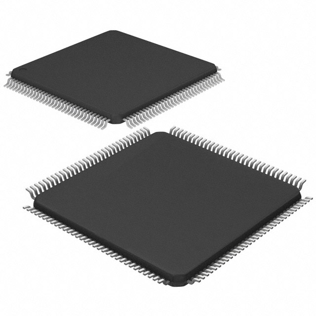
- Part No.:
- MEC1414-I/NU
- Manufacturer:
- Microchip Technology
- Category:
- Application Specific Microcontrollers
- Package:
- 128-TQFP
- Datasheet:
-
 MEC1414-I/NU.pdf
- Description:
- MEC, MIPS CORE, 128K SRAM, LPC &
- Quantity:
- Payment:

- Shipping:

Inventory:4,325
Please send an inquiry. Send us your inquiry, and we will respond immediately.
Product details
Overview
MEC1414-I/NU from Microchip Technology is a 32-bit embedded controller IC designed for notebook and tablet platform power management and I/O control. It integrates a MIPS32 M14K™ core, 128 kB SRAM (code + data), LPC and eSPI host interfaces, 106 GPIOs, and supports ACPI 3.0, Connected Standby, and secure boot with AES-128 encryption - deployed in system firmware for EC-based thermal, battery, and keyboard subsystem coordination.
For engineers reviewing the MEC1414-I/NU datasheet, MEC1414-I/NU pinout, MEC1414-I/NU application, or MEC1414-I/NU equivalent, key selection criteria include eSPI/LPC dual-host interface flexibility, VBAT-powered real-time timers (RTOS/Hibernation/Week), integrated SMBus/PS/2/UART peripherals, and 32 kHz crystal-supported low-power sleep state retention.
Technical Context
The MEC1414-I/NU implements a tightly coupled MIPS32 M14K™ microcontroller core with microMIPS instruction set support, programmable clock frequencies (48/12/3/1 MHz), and deep-sleep debug capability via 2-wire ICSP and Trace FIFO Debug Port (TFDP). Its interrupt architecture includes a vectored controller with maskable wake-up events and per-status-bit vector generation.
Host communication is handled through dual-mode configurable interfaces: Intel eSPI-compliant (Peripheral/VW/OOB/Flash channels) and LPC 1.1-compatible (with CLKRUN#, SERIRQ, SMI#, EC_SCI# support), both operating at 19.2–33 MHz bus speeds and sharing pin resources with GPIOs on the 128-VTQFP package.
Key Specifications
| Parameter | Value and Actual Design Meaning |
|---|---|
| Core Architecture | MIPS32 M14K™ with microMIPS compatibility and hardware multiply/divide unit |
| SRAM Capacity | 128 kB total (code + data), plus 64 B battery-backed SRAM for persistent state |
| Host Interfaces | LPC 1.1 and Intel eSPI v1.0 compliant; pin-multiplexed, firmware-configurable at boot |
| Real-Time Timers | RTOS Timer (32 kHz, runs in all sleep states), Hibernation Timer (0.5 ms–128 min wakeup), Week Timer (1 s–8.5 yr alarm) |
| Power Management | ACPI 3.0 & PC2001 compliant; VTR/VBAT dual standby planes; <10 µA sleep current typical |
| Secure Boot | ROM loader supporting 4 flash images, CRC-32 validation, and AES-128 encrypted firmware loading |
| Peripherals | 3x SMBus 2.0 controllers, 2x PS/2 ports, 8x PWM outputs, 2x tachometer inputs, 8x ADC channels (10-bit, 10 µs), 2x DACs (8-bit) |
Pinout & Package
MEC1414-I/NU is housed in a 128-pin VTQFP (14 × 14 mm, 0.4 mm pitch), RoHS-compliant package with exposed thermal pad. Pin functions are dynamically configurable via firmware-controlled GPIO registers; primary interface pins (eSPI/LPC) share physical terminals with general-purpose I/O.
| Pin/Terminal | Circuit Role | Design Meaning |
|---|---|---|
| GPIO034 | eSPI_CLK / PCI_CLK | Configurable as eSPI clock input or LPC PCI clock; requires firmware ALT FUNC2 or FUNC1 setting |
| GPIO040–043 | eSPI_IO0–IO3 / LAD0–LAD3 | Quad bidirectional data lines shared between eSPI and LPC; mode selected at boot via pin control register |
| GPIO044 | eSPI_CS# / LFRAME_N | Chip select (eSPI) or frame signal (LPC); active-low, critical for host interface initialization sequence |
| GPIO061 | eSPI_RESET# / LPC_PD# | Resets eSPI peripheral or asserts LPC power-down; not electrically compatible across modes |
| GPIO063 | eSPI_ALERT# / SERIRQ | Interrupt request signaling: eSPI alert or LPC serial IRQ; routed to PCH via dedicated trace |
| VTR_33_18 | Standby Power Supply | Selectable 3.3 V or 1.8 V rail; enables 10 GPIOs to operate at lower voltage when using eSPI/I2C host interface |
Key Features
| Feature | Design Value |
|---|---|
| Secure Firmware Loading | AES-128 decryption and CRC-32 validation of SPI flash images during boot, enabling trusted execution and crisis recovery over keyboard scan pins |
| Multi-Mode Host Interface | Firmware-selectable LPC or eSPI operation on shared pins - eliminates need for board-level interface redesign across platform generations |
| Battery-Powered Timing | RTOS, Hibernation, and Week Timers all driven by 32 kHz source and retain counting during VCC power loss - enables accurate wake scheduling without host involvement |
| Integrated Power Fail Detection | Dedicated hardware register reports VCC power-good status and triggers immediate firmware response to brown-out or shutdown events |
| Debug in Deep Sleep | 2-wire ICSP and TFDP maintain full visibility into CPU state and memory even during heavy/deep sleep - no wake required for breakpoint inspection |
Applications
| Thermal Management System | Battery Health Monitoring |
|---|---|
Use Scenario: Real-time fan speed control and thermistor-based temperature sampling in ultrabook chassis. IC Role / Device Role / Timing Role: Embedded controller executing closed-loop PWM regulation using 8-channel ADC inputs and 8x PWM outputs, synchronized to RTOS Timer for consistent 100 ms sampling intervals. Use Value: Enables precise thermal throttling without OS intervention, reducing latency by >15 ms versus host-driven polling and maintaining sub-1°C sensor accuracy across S0–S5 states. | Use Scenario: Accurate battery charge/discharge cycle logging and state-of-charge estimation in detachable tablets. IC Role / Device Role / Timing Role: BGPO and VCI interfaces monitor battery pack presence and charger status; Week Timer maintains calendar-corrected charge history in 64 B VBAT-SRAM across full power cycles. Use Value: Preserves battery analytics across cold reboots and multi-week storage, eliminating reliance on host OS timekeeping and preventing SOC drift beyond ±0.5% per month. |
| Keyboard & Touchpad Subsystem | Connected Standby Power Orchestration |
Use Scenario: Low-latency matrix scanning and PS/2 translation for keyboard and touchpad in clamshell notebooks. IC Role / Device Role / Timing Role: Dedicated 18×8 keyboard scan controller with PreDrive Mode; dual PS/2 controllers handle independent keyboard/mouse protocols while remaining active in S3/S4 suspend. Use Value: Achieves <20 ms keypress-to-interrupt latency and supports edge-triggered wake from PS/2 activity - meeting Intel's CS requirements for instant-resume UX. | Use Scenario: Coordinating platform-wide low-power transitions during Windows Connected Standby (S0ix). IC Role / Device Role / Timing Role: ACPI-ECI and PM1 block interfaces manage RSMRST# assertion, SCI event generation, and VTR/VBAT power plane sequencing under firmware control. Use Value: Reduces S0ix exit latency to <50 ms and ensures reliable wake from USB/keyboard events without PCH assistance - critical for sub-2W idle power targets. |
Equivalent & Alternatives
The following parts are listed as comparable options for similar embedded controller applications.
| Alternative Part | Technical Difference | Application Difference | Selection Advice |
|---|---|---|---|
| MEC1414-NU | Same silicon, industrial-grade (-40°C to +85°C) vs. extended industrial (-40°C to +105°C) for MEC1414-I/NU; identical pinout, firmware, and feature set | Targeting commercial notebooks instead of ruggedized 2-in-1s or automotive-adjacent tablets requiring higher thermal margin | Select MEC1414-I/NU when operating ambient exceeds 85°C or sustained junction temperature must remain below 125°C under full peripheral load. |
| MEC1416-I/NU | Same package and temperature grade, but 160 kB SRAM (vs. 128 kB) and additional eSPI channel support; pin-compatible with shared footprint | Suitable for platforms adding BIOS-level diagnostics, larger firmware stacks, or dual eSPI peripheral channel requirements (e.g., separate flash + out-of-band) | Choose MEC1416-I/NU only if firmware size exceeds 120 kB or eSPI OOB channel usage is confirmed - no benefit for standard LPC/eSPI dual-mode designs. |
Compared with MEC1414-NU, the MEC1414-I/NU offers extended thermal reliability without firmware or layout changes, while MEC1416-I/NU provides scalable memory and eSPI bandwidth - making MEC1414-I/NU optimal for thermally constrained, cost-sensitive Connected Standby platforms where 128 kB SRAM suffices.
Availability
MEC1414-I/NU is available at Aetrix Electronics and suitable for notebook thermal management, battery health monitoring, keyboard subsystem control, and Connected Standby power orchestration requiring stable component supply across long-life industrial and consumer programs.
Supply support for MEC1414-I/NU includes scheduled delivery planning, volume procurement assistance, BOM continuity management, traceable sourcing, and lifecycle availability coordination for OEM customers, industrial embedded developers, connected-device designers, and electronics production programs.
Manufacturer
Microchip Technology Inc. is a U.S.-based semiconductor company specializing in microcontrollers, analog devices, and security solutions for embedded systems.
The MEC140x/1x product line delivers highly configurable, mixed-signal embedded controllers optimized for PC-class power management, I/O consolidation, and firmware-defined system control in notebooks and tablets.
FAQ
What host interface modes does the MEC1414-I/NU support, and how are they configured?
The MEC1414-I/NU supports LPC 1.1 and Intel eSPI v1.0 host interfaces, both implemented on shared GPIO pins. Configuration occurs at boot via firmware writing to GPIO Pin Control Registers (e.g., 0x1000 for LPC, 0x2000 for eSPI) and activating the corresponding interface block. The MEC1414-I/NU does not support I2C as a host interface - that option is limited to MEC140x-SZ variants per the DS00001956E product table.
Does the MEC1414-I/NU include battery-backed memory, and what is its purpose?
Yes, the MEC1414-I/NU integrates 64 bytes of VBAT-powered SRAM. This memory retains critical state - such as RTC calendar data, Week Timer alarms, and firmware configuration flags - during complete system power loss. It operates independently of VCC and remains functional as long as VBAT is present, enabling accurate wake scheduling and persistent device identity across cold boots.
How does the MEC1414-I/NU implement secure boot, and what encryption standards are supported?
The MEC1414-I/NU uses a ROM-based Secure Boot Loader that validates and decrypts firmware images from external SPI flash. It supports CRC-32 integrity checking and AES-128 symmetric encryption for image confidentiality. The loader permits up to four code images in shared flash and enables crisis recovery via keyboard matrix scan pins - ensuring authenticated, tamper-resistant firmware execution from power-on reset.
What real-time timer capabilities does the MEC1414-I/NU provide for low-power system wake events?
The MEC1414-I/NU provides three independent 32 kHz–driven timers: the RTOS Timer (continues counting in all sleep states), Hibernation Timer (programmable 0.5 ms–128 min wake interval), and Week Timer (calendar-aware alarms from 1 second to 8.5 years). All timers generate wake-capable interrupts and halt only when the EC core is halted (e.g., during JTAG debug), ensuring deterministic low-power scheduling.
Is the MEC1414-I/NU pin-compatible with other members of the MEC140x/1x family, and which variants share the same 128-VTQFP package?
Yes, the MEC1414-I/NU is pin-compatible with all 128-VTQFP variants in the MEC140x/1x family, including MEC1404-NU, MEC1406-NU, MEC1408-NU, MEC1414-NU, MEC1416-NU, and MEC1418-NU. Differences are limited to firmware-configurable features (eSPI support), SRAM size (128/160/192 kB), and temperature grade - no PCB redesign is needed when upgrading within the 128-VTQFP footprint.
MEC1414-I/NU Specifications
- Product attributes
- Attribute value
- Manufacturer:
- Microchip Technology
- Series:
- -
- Package/Case:
- 128-TQFP
- Packaging:
- Tray
- Product Status:
- Active
- Programmable:
- Not Verified
- Applications:
- Keyboard and Embedded Controller
- Core Processor:
- MIPS32® M14K™
- Program Memory Type:
- External Program Memory
- Controller Series:
- -
- RAM Size:
- 128K x 8
- Interface:
- I2C, LPC, SMBus, SPI, UART
- Number of I/O:
- 106
- Voltage - Supply:
- 1.71V ~ 3.465V
- Operating Temperature:
- -40°C ~ 85°C
- Grade:
- -
- Qualification:
- -
- Mounting Type:
- Surface Mount
- Supplier Device Package:
- 128-VTQFP (14x14)
MEC1414-I/NU FAQ
1.How can I place an order for MEC1414-I/NU through Aetrix?
Please submit a Request for Quotation (RFQ) for MEC1414-I/NU on Aetrix. Our sales agent will provide a competitive quotation and guide you through the order confirmation once you accept the terms.
2.Are the price and stock information for MEC1414-I/NU reliable?
The price and inventory of MEC1414-I/NU are updated periodically and may fluctuate due to market conditions. Stock and pricing data are typically refreshed every 24 hours. Quotation validity for MEC1414-I/NU is usually 5 days.
3.What payment methods are accepted for MEC1414-I/NU?
We accept Wire Transfer, PayPal, Credit Card, Western Union, MoneyGram, and Escrow for MEC1414-I/NU transactions.
Note: Certain payment methods may incur a processing fee.
4.How is shipping managed for MEC1414-I/NU?
MEC1414-I/NU orders can be shipped via leading logistics carriers, including DHL, UPS, FedEx, TNT, or Registered Mail.
Once your MEC1414-I/NU order is processed, you will receive an email with the shipment details and tracking number.
Note: Tracking information may take up to 24 hours to appear. Express delivery typically takes 3–5 business days.
5.How can I obtain technical support or documentation for MEC1414-I/NU?
For technical support, including MEC1414-I/NU datasheets, pinout diagrams, or application guidance, please contact our engineering support team. They can provide detailed documentation and assistance for your MEC1414-I/NU requirements.
6.How does Aetrix verify that MEC1414-I/NU is sourced from the original manufacturer or authorized distributors?
All MEC1414-I/NU products on Aetrix are procured from qualified distributors and authorized channels. Our dedicated quality assurance team conducts strict verification, including traceability checks and, if necessary, third-party testing. This ensures that MEC1414-I/NU meets industry standards.
7.What is the process for return or replacement of MEC1414-I/NU?
All MEC1414-I/NU units undergo pre-shipment inspection (PSI). If there is an issue with MEC1414-I/NU, returns or replacements are accepted under the following conditions:
1.Quantity discrepancies, incorrect items, or visible external defects (such as breakage or corrosion), acknowledged by Aetrix.
2.The issue is reported within 90 days of delivery.
3.The MEC1414-I/NU part is unused and in its original packaging.
Return procedure for MEC1414-I/NU:
1.Submit a request within 90 days.
2.Obtain a Return Material Authorization (RMA) from Aetrix.
MEC1414-I/NU Tags

-
CYPD3175-24LQXQ
Infineon Technologies

-
SLB9672VU20FW1523XTMA1
Infineon Technologies

-
SLB9670VQ20FW785XTMA1
Infineon Technologies
-
SLB9672XU20FW1523XTMA1
Infineon Technologies
-
SLB9673XU20FW2613XTMA1
Infineon Technologies

-
CYPD3125-40LQXIT
Infineon Technologies

-
AT97SC3204-U2A1A-20
Microchip Technology
-
AT97SC3204-U2A1A-10
Microchip Technology
-
SLM9670AQ20FW1311XTMA1
Infineon Technologies
-
SLB9672XU20FW1613XTMA1
Infineon Technologies
-
SLB9672AU20FW1613XTMA1
Infineon Technologies
-
SLB9673AU20FW2613XTMA1
Infineon Technologies
Tech Hub

A practical engineering and sourcing framework covering lifecycle verification, lifetime-buy calculations, replacement qualification, supplier checks and counterfeit-risk controls.

TTL and CMOS logic families differ in thresholds, loading, output drive, power and timing. This engineering guide compares 74HC and 74HCT, calculates noise margins and checks 3.3 V/5 V compatibility.

A practical engineering guide to 3.3V and 5V logic compatibility, input thresholds, resistor dividers, translator ICs, MOSFET level shifting, I2C pull-ups, timing limits and power-sequencing risks.

The 74HC595 uses push-pull logic outputs, while the TPIC6B595 uses 50 V open-drain DMOS sinks for higher-power loads. This guide compares timing, current limits, 3.3 V interfacing, load wiring, thermal…

The 74HC595 converts serial data into eight stable parallel outputs. This guide covers pin functions, shift and storage timing, OE and MR behavior, drive-current limits, cascading, voltage compatibilit…

A technical comparison of level-sensitive latches and edge-triggered flip-flops, covering timing windows, setup and hold limits, master–slave operation, time borrowing, race-through, HDL inference and…

A D latch stores one bit while Enable controls when data can pass. This reference covers gate-level operation, truth tables, transparency, setup and hold timing, LE versus OE, common ICs and practical …

An SR latch stores one bit through cross-coupled feedback. This engineering reference covers NOR and NAND implementations, truth tables, forbidden-state recovery, gated operation, switch debouncing, fa…

Latch circuits retain one bit through feedback. This technical reference covers SR and D latches, truth tables, transparency, timing limits, latch-versus-flip-flop behavior, applications and common log…

An engineering guide to LED driver operation, constant-current and constant-voltage outputs, linear and switching topologies, dimming, IC selection, calculations, replacement compatibility, and fault c…


