
 My Inquiry
 My Account


Microchip Technology MEC1418-I/SZ
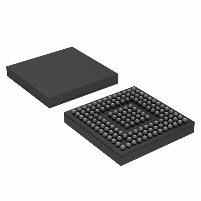
- Part No.:
- MEC1418-I/SZ
- Manufacturer:
- Microchip Technology
- Category:
- Application Specific Microcontrollers
- Package:
- 144-WFBGA
- Datasheet:
-
 MEC1418-I/SZ.pdf
- Description:
- MEC, MIPS CORE, 192K SRAM, LPC &
- Quantity:
- Payment:

- Shipping:

Inventory:3,371
Please send an inquiry. Send us your inquiry, and we will respond immediately.
Product details
Overview
MEC1418-I/SZ from Microchip Technology is a 32-bit ACPI-compliant embedded controller (EC) for notebook and tablet platforms, integrating a MIPS32 M14K™ core, 192 kB code-optimized SRAM, eSPI/LPC/I²C host interface support, 106 GPIOs, and full keyboard matrix scan (18×8). It operates at 3.3 V, supports Connected Standby, and delivers real-time power management via VTR/VBAT power planes and a 32 kHz RTC/Week Timer.
For engineers reviewing the MEC1418-I/SZ datasheet, MEC1418-I/SZ pinout, MEC1418-I/SZ application, or MEC1418-I/SZ equivalent, key selection criteria include eSPI compliance, 192 kB code SRAM capacity, 144-pin WFBGA package compatibility, secure boot with AES-128/CRC-32, and integrated PECI 3.0 and dual SMBus controllers for thermal and system monitoring in ultra-thin mobile designs.
Technical Context
The MEC1418-I/SZ implements a configurable mixed-signal I/O architecture centered on a microMIPS-compatible MIPS32 M14K core running at up to 48 MHz, with dedicated hardware for ACPI-ECI, 8042 emulation, and EC-to-host mailbox communication over LPC or eSPI. Its interrupt subsystem includes a vectored controller supporting wake-capable events from GPIO, RTC, Week Timer, and PS/2 interfaces.
Power management is implemented through three independent supply domains: VCC (main), VTR (standby), and VBAT (battery-backed), enabling sub-10 µA sleep current and hibernation timer wake-up intervals from 0.5 ms to 128 minutes. All peripherals-including ADC (10-bit, 8 ch), DAC (8-bit, 2 ch), PWM (8×), TACH (2×), and UART (NS16C550A-compatible)-are accessible in both active and suspend states.
Key Specifications
| Parameter | Value and Actual Design Meaning |
|---|---|
| Core Architecture | MIPS32 M14K™ with microMIPS support; enables compact firmware footprint and deterministic real-time response for EC tasks. |
| SRAM Capacity | 192 kB code-optimized + 32 kB data-optimized SRAM; sufficient for complex OEM EC firmware with multiple power-state handlers and sensor stacks. |
| Host Interface | eSPI, LPC, and I²C support; eSPI enables modern low-pin-count, high-reliability host communication with out-of-band channel and flash access. |
| Power Domains | VCC (runtime), VTR (standby), VBAT (battery); allows persistent RTC, week timer, and BGPO operation during S5/S4 without main power. |
| ADC/DAC | 8-channel 10-bit ADC (±0.5 LSB INL/DNL, 10 µs conversion); 2-channel 8-bit DAC; used for thermistor-based thermal monitoring and voltage-controlled fan regulation. |
| Timers | 32-bit RTOS timer (32 kHz, runs in all sleep states); hibernation timer (0.5 ms–128 min wake range); week timer with sub-second alarm and power-present detection. |
| Security | Secure boot ROM loader with AES-128 encryption and CRC-32 validation; supports 4 firmware images and crisis recovery via keyboard matrix pins. |
Pinout & Package
MEC1418-I/SZ is housed in a 144-ball WFBGA (RoHS-compliant) package with 0.5 mm pitch and 7 mm × 7 mm body size. Pin functions are fully configurable via firmware-controlled GPIO registers, with dedicated alternate functions for eSPI, LPC, PS/2, SMBus, UART, and keyboard scan.
| Pin/Terminal | Circuit Role | Design Meaning |
|---|---|---|
| ESPI_CLK / LPC_CLK | eSPI or LPC clock input | Selectable host interface clock; eSPI mode uses 20–66 MHz; LPC mode supports 19.2–33 MHz nominal bus speed. |
| ESPI_CS# / LFRAME# | eSPI chip select or LPC frame signal | Active-low enable for serial peripheral or parallel bus transaction; determines host interface activation at boot. |
| ESPI_IO[3:0] / LAD[3:0] | eSPI bidirectional data or LPC address/data | Quad I/O for eSPI peripheral/virtual wire channels; multiplexed with 4-bit LPC data/address bus for legacy compatibility. |
| VCI_IN0#, VCI_IN1#, VCI_OUT | VBAT-powered control interface | Enables wake-on-power-button or charger-detect logic using battery-backed inputs/outputs; latching/filtering configurable in firmware. |
| SYSPWR_PRES | System power presence input | Dedicated input for week timer alarm enablement; asserts only when VCC is stable, preventing spurious wake events during power ramp. |
| GPIO[105:0] | General-purpose I/O bank | 106 pins with programmable pull-up/down, edge-triggered wake, push-pull/open-drain drive, and power-well emulation for flexible board routing. |
Key Features
| Feature | Design Value |
|---|---|
| eSPI Compliance | Fully compliant with Intel eSPI specification; supports peripheral, virtual wire, OOB, and flash channels-enabling replacement of legacy LPC in next-gen notebooks. |
| Secure Boot Architecture | ROM-resident loader validates firmware image integrity via CRC-32 and AES-128 before execution; supports crisis recovery over keyboard scan pins without external SPI programmer. |
| Real-Time Power Management | 32-bit RTOS timer and hibernation timer operate continuously across all EC sleep states (including deep debug halt), ensuring precise wake scheduling without CPU intervention. |
| Thermal Monitoring Integration | Two 8-bit programmable comparators + 8-channel 10-bit ADC enable direct thermistor voltage sensing and fan control loop implementation without external analog front-end. |
| Multi-Protocol Host Connectivity | Single silicon supports LPC (legacy BIOS), eSPI (modern UEFI), and I²C (low-cost embedded) host interfaces-reducing platform BOM and enabling firmware reuse across product generations. |
Applications
| Ultrabook Power Management | Notebook Thermal Control |
|---|---|
Use Scenario: Managing S0ix/S3/S5 transitions, battery charging state, and instant-on resume in sub-15 mm clamshell notebooks. IC Role / Device Role / Timing Role: Primary ACPI Embedded Controller handling EC_SCI#, SMI#, and RSMRST# signaling; synchronizes with PCH via eSPI for coordinated power sequencing. Use Value: Enables <100 ms resume from S0ix using hibernation timer wake and VBAT-retained SRAM context, meeting Intel Project Athena responsiveness requirements. |
Use Scenario: Real-time thermal throttling of CPU/GPU based on thermistor readings from motherboard VRMs and heatsinks. IC Role / Device Role / Timing Role: ADC-driven thermal sensor hub feeding data to firmware PID loop; drives 8-channel PWM outputs to regulate dual-fan cooling profiles. Use Value: Achieves ±1°C thermal accuracy using internal 10-bit ADC and programmable comparators-eliminating need for external thermal ICs and reducing BOM count by one component. |
| Convertible Tablet System Monitor | Detachable Keyboard EC Subsystem |
Use Scenario: Detecting hinge angle, stylus presence, and battery status in 2-in-1 tablets with rotating displays and detachable accessories. IC Role / Device Role / Timing Role: GPIO-interrupt-driven system monitor interfacing with Hall sensors and battery fuel gauges; communicates status via eSPI virtual wire to host OS. Use Value: Uses VCI_IN/OUT pins to detect lid open/close and charger insertion while maintaining <5 µA standby current-extending battery life in tablet-only mode. |
Use Scenario: Providing keyboard matrix scanning, LED breathing control, and USB-C PD status reporting in detachable keyboard docks. IC Role / Device Role / Timing Role: Dedicated EC managing 18×8 keyboard scan, 3-channel breathing PWM for status LEDs, and SMBus communication with dock PD controller. Use Value: Leverages 64-byte battery-backed SRAM to retain keyboard layout and LED state across full system power cycles-ensuring consistent UX after dock reattachment. |
Equivalent & Alternatives
The following parts are listed as comparable options for similar embedded controller applications.
| Alternative Part | Technical Difference | Application Difference | Selection Advice |
|---|---|---|---|
| MEC1416-SZ | 160 kB code SRAM (vs. 192 kB); identical 144-WFBGA package, eSPI/LPC/I²C support, and peripheral set. | Suitable for firmware with smaller memory footprint; no change to PCB layout or driver stack required. | Select MEC1416-SZ when firmware binary size is ≤150 kB and cost optimization is prioritized over future firmware expansion headroom. |
| IT5570E-BFQJ | ARM Cortex-M0+ core; 128 kB Flash + 16 kB SRAM; supports LPC only (no eSPI); lacks PECI 3.0 and BC-Link. | Targeted at legacy BIOS-based notebooks where eSPI migration is not planned and thermal telemetry requirements are minimal. | Choose IT5570E-BFQJ only for cost-sensitive designs requiring basic keyboard/ACPI EC functionality without advanced power or thermal features. |
Compared with MEC1416-SZ, the MEC1418-I/SZ provides 32 kB additional code SRAM for enhanced firmware capabilities like multi-zone thermal modeling or secure firmware update stacks; versus IT5570E-BFQJ, it delivers eSPI readiness, PECI 3.0 for CPU temperature reporting, and BC-Link extensibility for companion I/O chips-making it the only option for modern Windows 11–certified convertible platforms.
Availability
MEC1418-I/SZ is available at Aetrix Electronics and suitable for ultrabook power sequencing, notebook thermal management, and convertible tablet system monitoring requiring stable component supply, long-term lifecycle support, and RoHS-compliant packaging.
Supply support for MEC1418-I/SZ includes scheduled delivery planning, volume procurement assistance, BOM continuity management, traceable sourcing, and lifecycle availability coordination for OEM customers, industrial embedded developers, connected-device designers, and electronics production programs.
Manufacturer
Microchip Technology Inc. is a global semiconductor company specializing in microcontrollers, analog devices, and security solutions for embedded systems, with leadership in automotive, industrial, and computing markets.
The MEC140x/1x family-including MEC1418-I/SZ-is designed as a highly configurable, mixed-signal embedded controller platform for notebook, tablet, and 2-in-1 PC architectures, emphasizing ACPI compliance, ultra-low-power operation, and seamless integration with Intel PCH and AMD chipset ecosystems.
FAQ
What host interface protocols does the MEC1418-I/SZ support?
The MEC1418-I/SZ supports three host interface protocols: Intel eSPI (compliant with eSPI specification), LPC (LPC Specification 1.1 compatible), and I²C (SMBus 2.0 compatible). Firmware configuration determines which interface is active at boot; eSPI is recommended for new Windows 11–certified designs due to its enhanced reliability and bandwidth over legacy LPC.
Does the MEC1418-I/SZ include built-in secure boot functionality?
Yes, the MEC1418-I/SZ includes a Secure Boot ROM Loader that validates firmware images using CRC-32 and AES-128 encryption before execution. It supports up to four firmware images in shared flash and enables crisis recovery via keyboard matrix scan pins-ensuring robust firmware integrity and field-upgrade resilience without external programming hardware.
What is the role of the VCI interface in the MEC1418-I/SZ?
The VBAT-powered VCI (VBAT-Powered Control Interface) in the MEC1418-I/SZ consists of two active-low inputs, one active-high input, and one active-high output-all powered by VBAT. It enables critical power-event detection (e.g., power button press, AC adapter insertion) and wake signaling during S5/S4 states, with optional filtering and latching controlled entirely in firmware.
How many GPIOs does the MEC1418-I/SZ provide, and what are their key capabilities?
The MEC1418-I/SZ provides 106 GPIOs with full firmware configurability: each supports asynchronous rising/falling edge wake interrupts, push-pull or open-drain output drive, programmable pull-up/pull-down resistors (auto-disabled when driven), and power-well emulation. These GPIOs are multiplexed with keyboard scan, SMBus, UART, and other peripheral functions per pin description tables.
Is the MEC1418-I/SZ compatible with Intel's Connected Standby specification?
Yes, the MEC1418-I/SZ is explicitly designed for Connected Standby (formerly InstantGo) compliance. It supports low-latency wake events, maintains VBAT-powered RTC/week timer operation, and enables host communication via eSPI virtual wire channels-all while sustaining sub-10 µA standby current in deepest sleep modes, meeting Intel's CS requirements for Windows 10/11 platforms.
MEC1418-I/SZ Specifications
- Product attributes
- Attribute value
- Manufacturer:
- Microchip Technology
- Series:
- -
- Package/Case:
- 144-WFBGA
- Packaging:
- Tray
- Product Status:
- Active
- Programmable:
- Not Verified
- Applications:
- Keyboard and Embedded Controller
- Core Processor:
- MIPS32® M14K™
- Program Memory Type:
- External Program Memory
- Controller Series:
- -
- RAM Size:
- 192K x 8
- Interface:
- I2C, LPC, SMBus, SPI, UART
- Number of I/O:
- 106
- Voltage - Supply:
- 1.71V ~ 3.465V
- Operating Temperature:
- -40°C ~ 85°C
- Grade:
- -
- Qualification:
- -
- Mounting Type:
- Surface Mount
- Supplier Device Package:
- 144-WFBGA (9x9)
MEC1418-I/SZ FAQ
1.How can I place an order for MEC1418-I/SZ through Aetrix?
Please submit a Request for Quotation (RFQ) for MEC1418-I/SZ on Aetrix. Our sales agent will provide a competitive quotation and guide you through the order confirmation once you accept the terms.
2.Are the price and stock information for MEC1418-I/SZ reliable?
The price and inventory of MEC1418-I/SZ are updated periodically and may fluctuate due to market conditions. Stock and pricing data are typically refreshed every 24 hours. Quotation validity for MEC1418-I/SZ is usually 5 days.
3.What payment methods are accepted for MEC1418-I/SZ?
We accept Wire Transfer, PayPal, Credit Card, Western Union, MoneyGram, and Escrow for MEC1418-I/SZ transactions.
Note: Certain payment methods may incur a processing fee.
4.How is shipping managed for MEC1418-I/SZ?
MEC1418-I/SZ orders can be shipped via leading logistics carriers, including DHL, UPS, FedEx, TNT, or Registered Mail.
Once your MEC1418-I/SZ order is processed, you will receive an email with the shipment details and tracking number.
Note: Tracking information may take up to 24 hours to appear. Express delivery typically takes 3–5 business days.
5.How can I obtain technical support or documentation for MEC1418-I/SZ?
For technical support, including MEC1418-I/SZ datasheets, pinout diagrams, or application guidance, please contact our engineering support team. They can provide detailed documentation and assistance for your MEC1418-I/SZ requirements.
6.How does Aetrix verify that MEC1418-I/SZ is sourced from the original manufacturer or authorized distributors?
All MEC1418-I/SZ products on Aetrix are procured from qualified distributors and authorized channels. Our dedicated quality assurance team conducts strict verification, including traceability checks and, if necessary, third-party testing. This ensures that MEC1418-I/SZ meets industry standards.
7.What is the process for return or replacement of MEC1418-I/SZ?
All MEC1418-I/SZ units undergo pre-shipment inspection (PSI). If there is an issue with MEC1418-I/SZ, returns or replacements are accepted under the following conditions:
1.Quantity discrepancies, incorrect items, or visible external defects (such as breakage or corrosion), acknowledged by Aetrix.
2.The issue is reported within 90 days of delivery.
3.The MEC1418-I/SZ part is unused and in its original packaging.
Return procedure for MEC1418-I/SZ:
1.Submit a request within 90 days.
2.Obtain a Return Material Authorization (RMA) from Aetrix.
MEC1418-I/SZ Tags

-
CYPD3175-24LQXQ
Infineon Technologies

-
SLB9672VU20FW1523XTMA1
Infineon Technologies

-
SLB9670VQ20FW785XTMA1
Infineon Technologies
-
SLB9672XU20FW1523XTMA1
Infineon Technologies
-
SLB9673XU20FW2613XTMA1
Infineon Technologies

-
CYPD3125-40LQXIT
Infineon Technologies

-
AT97SC3204-U2A1A-20
Microchip Technology
-
AT97SC3204-U2A1A-10
Microchip Technology
-
SLM9670AQ20FW1311XTMA1
Infineon Technologies
-
SLB9672XU20FW1613XTMA1
Infineon Technologies
-
SLB9672AU20FW1613XTMA1
Infineon Technologies
-
SLB9673AU20FW2613XTMA1
Infineon Technologies
Tech Hub

TTL and CMOS logic families differ in thresholds, loading, output drive, power and timing. This engineering guide compares 74HC and 74HCT, calculates noise margins and checks 3.3 V/5 V compatibility.

A practical engineering guide to 3.3V and 5V logic compatibility, input thresholds, resistor dividers, translator ICs, MOSFET level shifting, I2C pull-ups, timing limits and power-sequencing risks.

The 74HC595 uses push-pull logic outputs, while the TPIC6B595 uses 50 V open-drain DMOS sinks for higher-power loads. This guide compares timing, current limits, 3.3 V interfacing, load wiring, thermal…

The 74HC595 converts serial data into eight stable parallel outputs. This guide covers pin functions, shift and storage timing, OE and MR behavior, drive-current limits, cascading, voltage compatibilit…

A technical comparison of level-sensitive latches and edge-triggered flip-flops, covering timing windows, setup and hold limits, master–slave operation, time borrowing, race-through, HDL inference and…

A D latch stores one bit while Enable controls when data can pass. This reference covers gate-level operation, truth tables, transparency, setup and hold timing, LE versus OE, common ICs and practical …

An SR latch stores one bit through cross-coupled feedback. This engineering reference covers NOR and NAND implementations, truth tables, forbidden-state recovery, gated operation, switch debouncing, fa…

Latch circuits retain one bit through feedback. This technical reference covers SR and D latches, truth tables, transparency, timing limits, latch-versus-flip-flop behavior, applications and common log…

An engineering guide to LED driver operation, constant-current and constant-voltage outputs, linear and switching topologies, dimming, IC selection, calculations, replacement compatibility, and fault c…

Operational amplifier guide covering op amp basics, feedback, ideal vs real op amps, common configurations, buffer circuits, offset, bias current, gain-bandwidth, slew rate, rail-to-rail limits and sel…


