
 My Inquiry
 My Account


Microchip Technology MEC1527H-B0-I/SZ
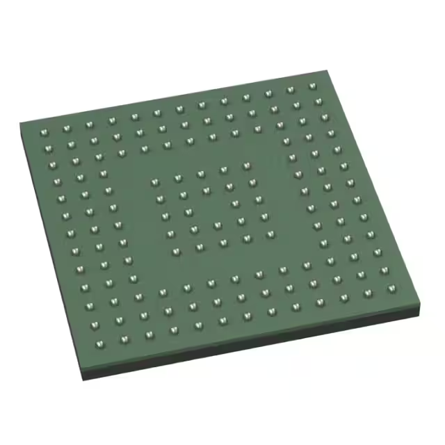
- Part No.:
- MEC1527H-B0-I/SZ
- Manufacturer:
- Microchip Technology
- Category:
- Application Specific Microcontrollers
- Package:
- 144-WFBGA
- Datasheet:
-
 MEC1527H-B0-I/SZ.pdf
- Description:
- EMBEDDED CTLR 256KB SRAM 512KB S
- Quantity:
- Payment:

- Shipping:

Inventory:4,800
Please send an inquiry. Send us your inquiry, and we will respond immediately.
Product details
Overview
MEC1527H-B0-I/SZ from Microchip Technology is a low-power ARM® Cortex-M4 embedded controller designed for notebook PC keyboard and system management functions. It integrates 256 KB SRAM (224 KB code + 32 KB data), 4 Mbit in-chip SPI flash (SST25PF040C), eSPI host interface compliant with Intel eSPI Spec v1.0.MEC152x, and supports all five ACPI power states (S0–S5) with light/heavy sleep modes.
For engineers reviewing the MEC1527H-B0-I/SZ datasheet, MEC1527H-B0-I/SZ pinout, MEC1527H-B0-I/SZ application, or MEC1527H-B0-I/SZ equivalent, key selection considerations include its 144-pin WFBGA package, dual-voltage (1.8 V/3.3 V) GPIO banks, hardware-accelerated AES-256/ECDSA/SHA-384 security, and native support for Master/Slave Attached Flash Sharing (MAFS/SAFS) over eSPI.
Technical Context
The MEC1527H-B0-I/SZ implements an ARM Cortex-M4 core running at up to 48 MHz with nested vectored interrupt controller (NVIC), EC interrupt aggregator, and JTAG/SWD debug interfaces. Its memory subsystem includes 256 KB SRAM, 64-byte battery-backed SRAM, 4 Kbits OTP, ROM with secure boot loader, and 4 Mbit integrated SPI flash - exclusive to the MEC1527 variant per Table 1-1.
Power management is tightly coupled to ACPI compliance: chip-level light/heavy sleep modes align with S0 connected standby and S3–S5 system states; wake events include RTC, week timer, hibernation timer, GPIO, PS/2, and eSPI commands. The eSPI interface supports all four channels (peripheral, virtual wires, OOB, runtime flash access) at up to 66 MHz and enforces region-based protection for SAFS.
Key Specifications
| Parameter | Value and Actual Design Meaning |
|---|---|
| Core | ARM Cortex-M4 @ 48 MHz max; fixed-point, 4 GB address space, NVIC with 8 priority levels |
| Memory | 256 KB SRAM (224 KB code-optimized + 32 KB data-optimized), 64 B battery-backed SRAM, 4 Mbit in-chip SPI flash |
| eSPI Interface | Intel eSPI v1.0.MEC152x compliant; supports MAFS/SAFS, 4-channel operation, up to 66 MHz |
| Security | Hardware AES-256, ECDSA p-384, SHA-384, RSA 1024–4096, TRNG, lockable OTP for keys |
| Power Modes | ACPI S0–S5 support; chip-level light/heavy sleep; standby current minimized during normal operation |
| Package | 144-pin WFBGA; dual IO voltage regions (1.8 V / 3.3 V); 0.5 mm pitch |
| Peripherals | 5 SMBus/I²C controllers, 3 UARTs (NS16C550A-compatible), 9 PWM, 4 tach inputs, 8-channel 10/12-bit ADC, RTC, week timer |
Pinout & Package
MEC1527H-B0-I/SZ is housed in a 144-pin Wafer-Level Fine-Pitch Ball Grid Array (WFBGA) package with 0.5 mm ball pitch and 10 mm × 10 mm body size. Pin mapping follows Microchip's DS00003427F-page 15 pin configuration diagram.
| Pin/Terminal | Circuit Role | Design Meaning |
|---|---|---|
| VCC | Runtime power supply | 3.3 V input for active-mode logic and I/O; monitored for system power presence |
| VBAT | Battery backup supply | 1.8–3.6 V input powering RTC, week timer, hibernation timer, and 64 B SRAM during main power loss |
| VTR_CORE | Suspend rail supply | 1.8 V core supply enabling instant-on wake from deep sleep without full re-initialization |
| eSPI_CLK / eSPI_CS# / eSPI_IO[0:3] | eSPI physical interface | Dedicated differential clock and single-ended control/data lines for full eSPI channel support (peripheral, VW, OOB, flash) |
| GPIO_00–GPIO_127 | Configurable I/O bank | Two independent voltage regions (1.8 V / 3.3 V); each pin supports interrupt-on-edge/level, glitch filtering, and programmable drive strength |
| RTC_XTAL_IN / RTC_XTAL_OUT | 32.768 kHz crystal interface | Connects external crystal for battery-backed RTC, week timer, and hibernation timer timing reference |
Key Features
| Feature | Design Value |
|---|---|
| Secure Boot Architecture | Hardware-enforced authentication of SPI flash firmware images using ECDSA p-384 and SHA-384 before execution |
| In-Chip SPI Flash | 4 Mbit integrated SST25PF040C eliminates need for external SPI flash in basic implementations; accessible via dedicated QMSPI controller |
| eSPI SAFS Bridge | Enables Slave Attached Flash Sharing with region-based locking-restricts BIOS, ME, and EC access to designated flash partitions |
| ACPI Power State Mapping | Direct hardware support for all five ACPI states (S0–S5); light/heavy sleep modes map precisely to S0i2/S0i3 and S3/S4 entry/exit sequences |
| Battery-Powered Timers | Week timer and hibernation timer operate from VBAT only; generate wake events with resolution from 0.5 ms to 8.5 years without main power |
Applications
| Ultra-Low-Power Notebook EC | Secure Firmware Platform |
|---|---|
Use Scenario: Embedded controller in thin-and-light Windows laptops requiring instant-on resume, fan control, keyboard/mouse interface, and thermal monitoring. IC Role / Device Role / Timing Role: Primary ACPI-compliant embedded controller managing S0–S5 transitions, GPIO-based sensor reads, PWM fan control, and RTC/calendar functions. Use Value: Integrated 4 Mbit SPI flash reduces BOM count; dual-voltage GPIO enables direct interfacing with both legacy 3.3 V and modern 1.8 V PCHs; light sleep mode maintains <100 µA standby current. | Use Scenario: Trusted platform root-of-trust implementation where OEM firmware integrity must be verified before boot. IC Role / Device Role / Timing Role: Secure boot loader executing from ROM, validating signed firmware images in external SPI flash using hardware crypto accelerators. Use Value: Hardware ECDSA p-384 and SHA-384 engines enable sub-100ms image authentication; AES-256 encryption protects firmware confidentiality; OTP key storage prevents extraction. |
| eSPI-Based System Management | Battery-Backed Timekeeping Subsystem |
Use Scenario: Replacement for legacy LPC-based EC designs migrating to Intel eSPI architecture in next-gen motherboards. IC Role / Device Role / Timing Role: eSPI slave device providing peripheral channel access to keyboard scan, virtual wire signaling for lid open/close, and OOB messaging for debug. Use Value: Full eSPI v1.0.MEC152x compliance ensures interoperability with Intel PCHs; MAFS/SAFS support enables shared flash resource arbitration between BIOS, ME, and EC firmware. | Use Scenario: Always-on timekeeping and scheduled wake in systems with removable main battery but persistent coin-cell backup. IC Role / Device Role / Timing Role: VBAT-powered real-time clock, week timer, and hibernation timer delivering alarm interrupts independent of system power state. Use Value: Week timer supports 1-second to 8.5-year alarms with sub-week precision; hibernation timer provides 0.5 ms–128 minute wake granularity-all powered solely by VBAT. |
Equivalent & Alternatives
The following parts are listed as comparable options for similar embedded controller applications.
| Alternative Part | Technical Difference | Application Difference | Selection Advice |
|---|---|---|---|
| MEC1521H-B0-I/SZ | No integrated SPI flash; 128-pin VTQFP/WFBGA option; same core, memory, and eSPI features | Lacks on-die flash-requires external SPI device; suitable for cost-sensitive designs where flash flexibility is prioritized | Select when external flash topology is preferred or PCB layout favors 128-pin package |
| IT5570E-HN3J | ARM Cortex-M0+ core; no hardware crypto accelerators; 128 KB SRAM; 128-pin LQFP; eSPI v1.1 compliant | Lower performance and security tier; targets entry-level notebooks without secure boot requirements | Select for non-security-critical platforms needing basic eSPI EC functionality at lower cost |
Compared with MEC1527H-B0-I/SZ, MEC1521H-B0-I/SZ removes integrated flash but retains identical security and timing peripherals, while IT5570E-HN3J trades crypto acceleration and SRAM capacity for reduced footprint and cost-making it suitable only for non-secure, lower-feature notebook EC roles.
Availability
MEC1527H-B0-I/SZ is available at Aetrix Electronics and suitable for ultra-thin notebook design, secure firmware platform development, and eSPI-based system management applications requiring stable component supply, long-term lifecycle assurance, and traceable sourcing.
Supply support for MEC1527H-B0-I/SZ includes scheduled delivery planning, volume procurement assistance, BOM continuity management, traceable sourcing, and lifecycle availability coordination for OEM customers, industrial embedded developers, connected-device designers, and electronics production programs.
Manufacturer
Microchip Technology Inc. is a U.S.-based semiconductor company specializing in microcontrollers, analog devices, FPGAs, and security ICs, with global manufacturing and support infrastructure.
The MEC152x product line delivers highly configurable, low-power embedded controllers optimized for Windows notebook platforms-integrating ARM Cortex-M4 processing, eSPI host interface, hardware security, and battery-backed timing peripherals into a single die.
FAQ
What is the primary function of the MEC1527H-B0-I/SZ in a notebook system?
The MEC1527H-B0-I/SZ serves as the embedded controller (EC) managing keyboard/mouse scanning, thermal regulation, fan control, power sequencing, ACPI S0–S5 state transitions, and secure boot in Windows notebooks. Its ARM Cortex-M4 core executes OEM firmware to coordinate with the host CPU and PCH via eSPI, while integrated peripherals like RTC, week timer, and 4 Mbit SPI flash enable autonomous operation during system suspend.
Does the MEC1527H-B0-I/SZ support Intel eSPI specification version 1.2 or later?
No-the MEC1527H-B0-I/SZ implements Intel eSPI Specification v1.0.MEC152x as documented in DS00003427F. It supports all four eSPI channels (peripheral, virtual wires, OOB, runtime flash access) and features like MAFS/SAFS, but does not include enhancements introduced in v1.1 or v1.2 such as enhanced error reporting or new command sets. Compatibility with newer PCHs depends on backward support in the host chipset.
How does the integrated 4 Mbit SPI flash in the MEC1527H-B0-I/SZ differ from external flash solutions?
The MEC1527H-B0-I/SZ integrates a 4 Mbit SST25PF040C SPI flash directly on-die, eliminating the need for a discrete SPI flash IC in basic configurations. This reduces PCB area, BOM count, and signal routing complexity. Unlike external flash, the integrated version is accessed exclusively through the dedicated in-chip QMSPI controller and is not exposed on general-purpose SPI ports-ensuring deterministic timing and isolation from other peripherals.
Can the MEC1527H-B0-I/SZ operate with only VBAT applied and no VCC or VTR_CORE?
Yes-the MEC1527H-B0-I/SZ supports limited functionality under VBAT-only power: RTC, week timer, hibernation timer, and 64 B battery-backed SRAM remain fully operational. However, the ARM Cortex-M4 core, eSPI interface, GPIOs, and most peripherals require VTR_CORE (1.8 V) and/or VCC (3.3 V). VBAT-only mode enables wake event generation but not firmware execution or host communication.
What security mechanisms prevent unauthorized firmware modification on the MEC1527H-B0-I/SZ?
The MEC1527H-B0-I/SZ enforces firmware integrity via hardware-rooted secure boot: the ROM-based loader authenticates each SPI flash image using ECDSA p-384 signatures and SHA-384 hashes before loading. AES-256 encryption protects firmware confidentiality, while OTP stores private keys with 32-byte boundary locking. Rollback protection tracks up to 128 firmware revisions, and key revocation disables compromised signing keys-collectively preventing unsigned, tampered, or downgraded firmware execution.
MEC1527H-B0-I/SZ Specifications
- Product attributes
- Attribute value
- Manufacturer:
- Microchip Technology
- Series:
- -
- Package/Case:
- 144-WFBGA
- Packaging:
- Tray
- Product Status:
- Active
- Programmable:
- Not Verified
- Applications:
- Keyboard and Embedded Controller
- Core Processor:
- ARM® Cortex®-M4
- Program Memory Type:
- -
- Controller Series:
- MEC152x
- RAM Size:
- 256K x 8
- Interface:
- ACPI, eSPI, I2C, LPC, PECI, PS/2, QSPI, SPI, UART
- Number of I/O:
- 128
- Voltage - Supply:
- 1.71V ~ 3.465V
- Operating Temperature:
- -40°C ~ 85°C (TA)
- Grade:
- -
- Qualification:
- -
- Mounting Type:
- Surface Mount
- Supplier Device Package:
- 144-WFBGA (9x9)
MEC1527H-B0-I/SZ FAQ
1.How can I place an order for MEC1527H-B0-I/SZ through Aetrix?
Please submit a Request for Quotation (RFQ) for MEC1527H-B0-I/SZ on Aetrix. Our sales agent will provide a competitive quotation and guide you through the order confirmation once you accept the terms.
2.Are the price and stock information for MEC1527H-B0-I/SZ reliable?
The price and inventory of MEC1527H-B0-I/SZ are updated periodically and may fluctuate due to market conditions. Stock and pricing data are typically refreshed every 24 hours. Quotation validity for MEC1527H-B0-I/SZ is usually 5 days.
3.What payment methods are accepted for MEC1527H-B0-I/SZ?
We accept Wire Transfer, PayPal, Credit Card, Western Union, MoneyGram, and Escrow for MEC1527H-B0-I/SZ transactions.
Note: Certain payment methods may incur a processing fee.
4.How is shipping managed for MEC1527H-B0-I/SZ?
MEC1527H-B0-I/SZ orders can be shipped via leading logistics carriers, including DHL, UPS, FedEx, TNT, or Registered Mail.
Once your MEC1527H-B0-I/SZ order is processed, you will receive an email with the shipment details and tracking number.
Note: Tracking information may take up to 24 hours to appear. Express delivery typically takes 3–5 business days.
5.How can I obtain technical support or documentation for MEC1527H-B0-I/SZ?
For technical support, including MEC1527H-B0-I/SZ datasheets, pinout diagrams, or application guidance, please contact our engineering support team. They can provide detailed documentation and assistance for your MEC1527H-B0-I/SZ requirements.
6.How does Aetrix verify that MEC1527H-B0-I/SZ is sourced from the original manufacturer or authorized distributors?
All MEC1527H-B0-I/SZ products on Aetrix are procured from qualified distributors and authorized channels. Our dedicated quality assurance team conducts strict verification, including traceability checks and, if necessary, third-party testing. This ensures that MEC1527H-B0-I/SZ meets industry standards.
7.What is the process for return or replacement of MEC1527H-B0-I/SZ?
All MEC1527H-B0-I/SZ units undergo pre-shipment inspection (PSI). If there is an issue with MEC1527H-B0-I/SZ, returns or replacements are accepted under the following conditions:
1.Quantity discrepancies, incorrect items, or visible external defects (such as breakage or corrosion), acknowledged by Aetrix.
2.The issue is reported within 90 days of delivery.
3.The MEC1527H-B0-I/SZ part is unused and in its original packaging.
Return procedure for MEC1527H-B0-I/SZ:
1.Submit a request within 90 days.
2.Obtain a Return Material Authorization (RMA) from Aetrix.
MEC1527H-B0-I/SZ Tags

-
CYPD3175-24LQXQ
Infineon Technologies

-
SLB9672VU20FW1523XTMA1
Infineon Technologies

-
SLB9670VQ20FW785XTMA1
Infineon Technologies
-
SLB9672XU20FW1523XTMA1
Infineon Technologies
-
SLB9673XU20FW2613XTMA1
Infineon Technologies

-
CYPD3125-40LQXIT
Infineon Technologies

-
AT97SC3204-U2A1A-20
Microchip Technology
-
AT97SC3204-U2A1A-10
Microchip Technology
-
SLM9670AQ20FW1311XTMA1
Infineon Technologies
-
SLB9672XU20FW1613XTMA1
Infineon Technologies
-
SLB9672AU20FW1613XTMA1
Infineon Technologies
-
SLB9673AU20FW2613XTMA1
Infineon Technologies
Tech Hub

TTL and CMOS logic families differ in thresholds, loading, output drive, power and timing. This engineering guide compares 74HC and 74HCT, calculates noise margins and checks 3.3 V/5 V compatibility.

A practical engineering guide to 3.3V and 5V logic compatibility, input thresholds, resistor dividers, translator ICs, MOSFET level shifting, I2C pull-ups, timing limits and power-sequencing risks.

The 74HC595 uses push-pull logic outputs, while the TPIC6B595 uses 50 V open-drain DMOS sinks for higher-power loads. This guide compares timing, current limits, 3.3 V interfacing, load wiring, thermal…

The 74HC595 converts serial data into eight stable parallel outputs. This guide covers pin functions, shift and storage timing, OE and MR behavior, drive-current limits, cascading, voltage compatibilit…

A technical comparison of level-sensitive latches and edge-triggered flip-flops, covering timing windows, setup and hold limits, master–slave operation, time borrowing, race-through, HDL inference and…

A D latch stores one bit while Enable controls when data can pass. This reference covers gate-level operation, truth tables, transparency, setup and hold timing, LE versus OE, common ICs and practical …

An SR latch stores one bit through cross-coupled feedback. This engineering reference covers NOR and NAND implementations, truth tables, forbidden-state recovery, gated operation, switch debouncing, fa…

Latch circuits retain one bit through feedback. This technical reference covers SR and D latches, truth tables, transparency, timing limits, latch-versus-flip-flop behavior, applications and common log…

An engineering guide to LED driver operation, constant-current and constant-voltage outputs, linear and switching topologies, dimming, IC selection, calculations, replacement compatibility, and fault c…

Operational amplifier guide covering op amp basics, feedback, ideal vs real op amps, common configurations, buffer circuits, offset, bias current, gain-bandwidth, slew rate, rail-to-rail limits and sel…


