
 My Inquiry
 My Account


NXP Semiconductors MM908E626AVPEKR2
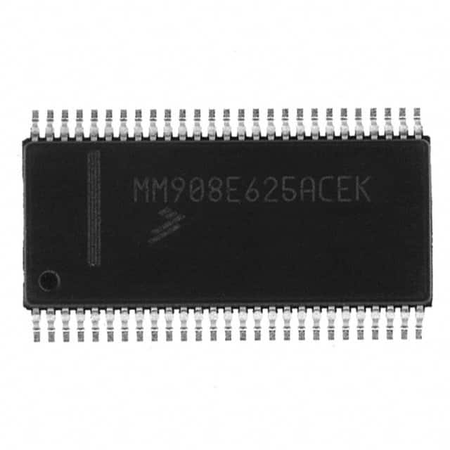
- Part No.:
- MM908E626AVPEKR2
- Manufacturer:
- NXP Semiconductors
- Category:
- Application Specific Microcontrollers
- Package:
- 54-SSOP (0.295", 7.50mm Width) Exposed Pad
- Datasheet:
-
 MM908E626AVPEKR2.pdf
- Description:
- IC STEPPER MOTOR DRVR 54SOIC
- Quantity:
- Payment:

- Shipping:

Inventory:2,750
Please send an inquiry. Send us your inquiry, and we will respond immediately.
Product details
Overview
MM908E626AVPEKR2 from NXP (formerly Freescale) is an integrated automotive stepper motor driver combining a 68HC08EY16 microcontroller and SMARTMOS analog control IC in a single 54-pin SOICW-EP package. It delivers 4 half-bridge outputs (RDS(ON) ≤ 500 mΩ), embedded LIN physical layer, 16 KB flash/512 B RAM, and on-chip voltage regulation - enabling compact climate control and headlight leveling systems.
For engineers reviewing the MM908E626AVPEKR2 datasheet, MM908E626AVPEKR2 pinout, MM908E626AVPEKR2 application, or MM908E626AVPEKR2 equivalent, key selection criteria include LIN bus compliance, bipolar stepper phase control via HB1–HB4, BEMF-based stall detection, and thermal-safe operation up to 115 °C case temperature.
Technical Context
The MM908E626AVPEKR2 integrates two dies: an HC08 MCU die with 8 MHz bus frequency, 10-bit ADC, dual 16-bit timers, ESCI, SPI, and ICG; and an analog die featuring four protected half-bridges, autonomous watchdog, LIN transceiver, HVDD switchable 5 V output, and VSUP down-scaler for diagnostics. Communication between dies occurs via internal SPI with SS, MOSI, MISO, and SPSCK routed internally.
Its LIN interface supports 20 kbaud with programmable slew rate, recessive/dominant thresholds tied to VSUP, and wake-up capability. The BEMF module interfaces directly with PTD0/TACH0/BEMF to detect motor stall or coil faults, while FGEN input sets current-limit PWM period (0.1–20 kHz), not duty cycle.
Key Specifications
| Parameter | Value and Actual Design Meaning |
|---|---|
| Core | M68HC08EY16 with 8 MHz max bus frequency - enables deterministic real-time motor control loops |
| Memory | 16 KB flash (15.872 KB user), 512 B RAM - sufficient for LIN stack + stepper commutation firmware |
| Half-bridge RDS(ON) | ≤ 500 mΩ HS / ≤ 500 mΩ LS at 25 °C - supports ≥1 A continuous phase current with low conduction loss |
| LIN Compliance | Meets ISO 17987-4:2016 electrical specs - 20 kbaud, VIL/VIH referenced to VSUP, ±600 µA bus leakage |
| Operating Temp | -40 °C to +115 °C case temperature - qualified for under-hood automotive environments |
| Voltage Regulator | 5.0 V ±2.5% @ 60 mA (VDDRUN) - powers MCU core; separate HVDD provides switchable 5 V for sensors |
| BEMF Detection | VBEMFL = -5.0 mV, VBEMFH = 0.0 V, hysteresis = 30 mV - enables reliable stall detection without external comparators |
Pinout & Package
MM908E626AVPEKR2 uses a 54-pin SOICW-EP (wide-body surface-mount) package with exposed thermal pad (EP) for enhanced heat dissipation. Pin count and layout match Freescale's documented 54-SOICW footprint, supporting standard reflow profiles per JEDEC J-STD-020C.
| Pin/Terminal | Circuit Role | Design Meaning |
|---|---|---|
| HB1–HB4 | Half-bridge outputs | Four independent power MOSFET pairs - configurable as bipolar stepper phases or DC motor H-bridges with short-circuit/overtemp protection |
| PTD0/TACH0/BEMF | MCU input | Direct connection point for analog die BEMF signal - enables stall detection and coil fault diagnosis in firmware |
| FGEN | Analog die input | Accepts PWM period timing only (0.1–20 kHz); internal logic generates current-limit duty cycle autonomously |
| LIN | LIN bus I/O | Single-wire bidirectional interface - connects to vehicle LIN network without external transceiver |
| RST_A / IRQ_A | Analog die control | Open-drain reset/interrupt outputs - wired to MCU RST/IRQ pins for coordinated system-level fault handling |
| VDD / HVDD | Regulated outputs | VDD supplies MCU core (5.0 V); HVDD is switchable 5.0 V output for Hall sensors or other resistive loads |
| VSUP1–VSUP3 | Main supply inputs | Three parallel 12 V battery inputs - reduce IR drop and improve current sharing across high-side drivers |
| GND1 / GND2 | Power ground | Dedicated high-current ground paths - isolate motor return currents from MCU/signal grounds |
Key Features
| Feature | Design Value |
|---|---|
| Integrated LIN Physical Layer | Eliminates need for external LIN transceiver - reduces BOM cost and PCB area in body electronics modules |
| BEMF-Based Stall Detection | Hardware-accelerated rotor position monitoring via PTD0 - enables closed-loop step verification without encoder feedback |
| Autonomous Watchdog (AWD) | Independent 40 µs oscillator with 8–34 ms timeout windows - ensures fail-safe recovery even if MCU hangs |
| Switchable HVDD Output | 5.0 V regulated output with 30 mA overcurrent shutdown - powers 3-pin Hall-effect sensors directly from chip |
| VSUP Down-Scaler (RATIOVSUP) | 5.1× nominal ratio (4.8–5.35) - enables accurate battery voltage monitoring using MCU ADC without external divider |
| Internal Die Temperature Sensor | 19 mV/°C slope, 2.1 V @ 25 °C - provides real-time junction temperature estimation for thermal derating |
Applications
| Automotive Climate Control | Adaptive Headlight Leveling |
|---|---|
Use Scenario: Precise airflow direction adjustment via stepper-driven blend doors in HVAC systems. IC Role / Device Role / Timing Role: MM908E626AVPEKR2 acts as standalone LIN node executing commutation, BEMF monitoring, and LIN message parsing. Use Value: Reduces component count by integrating MCU, driver, and LIN PHY - cuts board space by >40% vs discrete solutions. |
Use Scenario: Dynamic vertical aim correction of headlights based on vehicle pitch angle and load. IC Role / Device Role / Timing Role: MM908E626AVPEKR2 drives bipolar stepper motor while reporting position status via LIN to body controller. Use Value: Enables stall detection via BEMF to prevent motor burnout during mechanical obstruction - improves system reliability. |
| Industrial Valve Actuation | Medical Imaging Positioning |
Use Scenario: Accurate open/closed positioning of fluid control valves in factory automation equipment. IC Role / Device Role / Timing Role: MM908E626AVPEKR2 executes microstepping control and monitors current limits via low-side sensing. Use Value: Four half-bridges support dual-valve actuation or redundant drive - increases functional safety margin. |
Use Scenario: Fine positional control of X-ray detector gantries requiring silent, vibration-free motion. IC Role / Device Role / Timing Role: MM908E626AVPEKR2 implements smooth acceleration profiles using dual 16-bit timers and ADC feedback. Use Value: Integrated voltage regulator and HVDD eliminate need for external LDOs - simplifies power design for EMI-sensitive imaging systems. |
Equivalent & Alternatives
The following parts are listed as comparable options for similar integrated stepper motor driver applications.
| Alternative Part | Technical Difference | Application Difference | Selection Advice |
|---|---|---|---|
| MC33816AEK | 32-bit S12ZVM core, 64 KB flash, 6 half-bridges, CAN+LIN, higher integration | Targeted at higher-performance chassis/body modules requiring CAN diagnostics | Choose MC33816AEK when CAN bus connectivity and larger memory are required; MM908E626AVPEKR2 remains optimal for cost-sensitive LIN-only nodes. |
| DRV8837RGTR | Standalone dual H-bridge (no MCU, no LIN), 1.8 A per channel, 5.5–16 V supply | Requires external MCU and LIN transceiver - increases BOM and layout complexity | Use DRV8837RGTR only in non-LIN designs where full MCU integration is unnecessary and board space allows discrete implementation. |
Compared with MC33816AEK and DRV8837RGTR, MM908E626AVPEKR2 uniquely balances LIN-native communication, embedded 8-bit control, and four protected half-bridges in one package - making it the most direct solution for automotive stepper nodes where cost, size, and protocol alignment are critical.
Availability
MM908E626AVPEKR2 is available at Aetrix Electronics and suitable for automotive climate control, adaptive lighting, industrial valve actuation, and medical positioning systems requiring stable component supply across extended temperature ranges and long production lifecycles.
Supply support for MM908E626AVPEKR2 includes scheduled delivery planning, volume procurement assistance, BOM continuity management, traceable sourcing, and lifecycle availability coordination for OEM customers, industrial embedded developers, connected-device designers, and electronics production programs.
Manufacturer
NXP Semiconductors is a global semiconductor leader focused on secure connectivity solutions for automotive, industrial, and IoT applications, with deep expertise in automotive-grade mixed-signal integration.
The MM908E626AVPEKR2 belongs to NXP's SMARTMOS family - engineered specifically for cost-optimized, single-package motor control in automotive body electronics where LIN interoperability and functional safety are essential.
FAQ
What is the maximum continuous current per half-bridge output of the MM908E626AVPEKR2?
The MM908E626AVPEKR2 specifies a typical RDS(ON) of 425 mΩ (HS) and 400 mΩ (LS) at 25 °C. With thermal derating and safe operating area constraints, each half-bridge supports ≥1.0 A continuous current under 115 °C case temperature conditions - verified by internal overcurrent shutdown thresholds of 3.0 A (HS) and 2.5 A (LS).
Does the MM908E626AVPEKR2 require an external LIN transceiver?
No, the MM908E626AVPEKR2 includes a fully compliant LIN physical layer integrated into its analog die. The LIN pin connects directly to the vehicle's single-wire LIN bus without external components - meeting ISO 17987-4 electrical requirements including dominant/recessive thresholds, slew rate, and bus leakage.
How does BEMF detection work on the MM908E626AVPEKR2, and which pin is used?
BEMF detection on the MM908E626AVPEKR2 uses the analog die's dedicated BEMF pin, which must be connected to MCU pin PTD0/TACH0/BEMF. The MCU's built-in BEMF counter module samples this signal to detect rotor position, enabling stall detection and coil failure diagnosis without external circuitry.
What is the function of the FGEN pin on the MM908E626AVPEKR2?
The FGEN pin on the MM908E626AVPEKR2 accepts a frequency input (0.1–20 kHz) that defines the period of the half-bridge current-limit PWM waveform. Unlike a standard PWM input, FGEN does not accept duty cycle control - the analog die autonomously generates the appropriate duty cycle based on sensed current and programmed limit levels.
Can the MM908E626AVPEKR2 drive unipolar stepper motors?
The MM908E626AVPEKR2 is optimized for bipolar stepper motor control using its four half-bridge outputs (HB1–HB4) in dual-H-bridge configuration. While unipolar operation is not supported natively, firmware can emulate unipolar drive by selectively enabling high-side switches - though this sacrifices torque and efficiency compared to native bipolar mode.
MM908E626AVPEKR2 Specifications
- Product attributes
- Attribute value
- Manufacturer:
- NXP Semiconductors
- Series:
- -
- Package/Case:
- 54-SSOP (0.295", 7.50mm Width) Exposed Pad
- Packaging:
- Tape & Reel (TR)
- Product Status:
- Obsolete
- Programmable:
- Not Verified
- Applications:
- Mirror Control
- Core Processor:
- HC08
- Program Memory Type:
- FLASH (16kB)
- Controller Series:
- 908E
- RAM Size:
- 512 x 8
- Interface:
- SCI, SPI
- Number of I/O:
- 13
- Voltage - Supply:
- 8V ~ 18V
- Operating Temperature:
- -40°C ~ 115°C
- Grade:
- Automotive
- Qualification:
- -
- Mounting Type:
- Surface Mount
- Supplier Device Package:
- 54-SOIC-EP
MM908E626AVPEKR2 FAQ
1.How can I place an order for MM908E626AVPEKR2 through Aetrix?
Please submit a Request for Quotation (RFQ) for MM908E626AVPEKR2 on Aetrix. Our sales agent will provide a competitive quotation and guide you through the order confirmation once you accept the terms.
2.Are the price and stock information for MM908E626AVPEKR2 reliable?
The price and inventory of MM908E626AVPEKR2 are updated periodically and may fluctuate due to market conditions. Stock and pricing data are typically refreshed every 24 hours. Quotation validity for MM908E626AVPEKR2 is usually 5 days.
3.What payment methods are accepted for MM908E626AVPEKR2?
We accept Wire Transfer, PayPal, Credit Card, Western Union, MoneyGram, and Escrow for MM908E626AVPEKR2 transactions.
Note: Certain payment methods may incur a processing fee.
4.How is shipping managed for MM908E626AVPEKR2?
MM908E626AVPEKR2 orders can be shipped via leading logistics carriers, including DHL, UPS, FedEx, TNT, or Registered Mail.
Once your MM908E626AVPEKR2 order is processed, you will receive an email with the shipment details and tracking number.
Note: Tracking information may take up to 24 hours to appear. Express delivery typically takes 3–5 business days.
5.How can I obtain technical support or documentation for MM908E626AVPEKR2?
For technical support, including MM908E626AVPEKR2 datasheets, pinout diagrams, or application guidance, please contact our engineering support team. They can provide detailed documentation and assistance for your MM908E626AVPEKR2 requirements.
6.How does Aetrix verify that MM908E626AVPEKR2 is sourced from the original manufacturer or authorized distributors?
All MM908E626AVPEKR2 products on Aetrix are procured from qualified distributors and authorized channels. Our dedicated quality assurance team conducts strict verification, including traceability checks and, if necessary, third-party testing. This ensures that MM908E626AVPEKR2 meets industry standards.
7.What is the process for return or replacement of MM908E626AVPEKR2?
All MM908E626AVPEKR2 units undergo pre-shipment inspection (PSI). If there is an issue with MM908E626AVPEKR2, returns or replacements are accepted under the following conditions:
1.Quantity discrepancies, incorrect items, or visible external defects (such as breakage or corrosion), acknowledged by Aetrix.
2.The issue is reported within 90 days of delivery.
3.The MM908E626AVPEKR2 part is unused and in its original packaging.
Return procedure for MM908E626AVPEKR2:
1.Submit a request within 90 days.
2.Obtain a Return Material Authorization (RMA) from Aetrix.
MM908E626AVPEKR2 Tags

-
CYPD3175-24LQXQ
Infineon Technologies

-
SLB9672VU20FW1523XTMA1
Infineon Technologies

-
SLB9670VQ20FW785XTMA1
Infineon Technologies
-
SLB9672XU20FW1523XTMA1
Infineon Technologies
-
SLB9673XU20FW2613XTMA1
Infineon Technologies

-
CYPD3125-40LQXIT
Infineon Technologies

-
AT97SC3204-U2A1A-20
Microchip Technology
-
AT97SC3204-U2A1A-10
Microchip Technology
-
SLM9670AQ20FW1311XTMA1
Infineon Technologies
-
SLB9672XU20FW1613XTMA1
Infineon Technologies
-
SLB9672AU20FW1613XTMA1
Infineon Technologies
-
SLB9673AU20FW2613XTMA1
Infineon Technologies
Tech Hub

A practical engineering guide to 3.3V and 5V logic compatibility, input thresholds, resistor dividers, translator ICs, MOSFET level shifting, I2C pull-ups, timing limits and power-sequencing risks.

The 74HC595 uses push-pull logic outputs, while the TPIC6B595 uses 50 V open-drain DMOS sinks for higher-power loads. This guide compares timing, current limits, 3.3 V interfacing, load wiring, thermal…

The 74HC595 converts serial data into eight stable parallel outputs. This guide covers pin functions, shift and storage timing, OE and MR behavior, drive-current limits, cascading, voltage compatibilit…

A technical comparison of level-sensitive latches and edge-triggered flip-flops, covering timing windows, setup and hold limits, master–slave operation, time borrowing, race-through, HDL inference and…

A D latch stores one bit while Enable controls when data can pass. This reference covers gate-level operation, truth tables, transparency, setup and hold timing, LE versus OE, common ICs and practical …

An SR latch stores one bit through cross-coupled feedback. This engineering reference covers NOR and NAND implementations, truth tables, forbidden-state recovery, gated operation, switch debouncing, fa…

Latch circuits retain one bit through feedback. This technical reference covers SR and D latches, truth tables, transparency, timing limits, latch-versus-flip-flop behavior, applications and common log…

An engineering guide to LED driver operation, constant-current and constant-voltage outputs, linear and switching topologies, dimming, IC selection, calculations, replacement compatibility, and fault c…

Operational amplifier guide covering op amp basics, feedback, ideal vs real op amps, common configurations, buffer circuits, offset, bias current, gain-bandwidth, slew rate, rail-to-rail limits and sel…

Jumper cables guide covering safe connection order, red and black clamp placement, final ground connection, cable gauge, length, clamp quality, copper vs CCA cables, jump starter comparison and battery…


